
Related Manuals for Rockwell Automation 1768-L43


Summary of Contents for Rockwell Automation 1768-L43
- Page 1 1768 CompactLogix System Catalog Numbers 1768-L43 and 1768-L45 CompactLogix Controllers Quick Start...
- Page 2 Allen-Bradley, Rockwell Automation, Rockwell Software, Inc., CompactLogix, ControlLogix, FactoryTalk ME, Kinetix, Logix5000, Point I/O, Panelview Plus, PowerFlex, RSLinx, RSLinx Classic, RSLinx Enterprise, RSLogix, RSLogix 5000, RSLogix 5000 with PhaseManager, RSView Machine Edition, RSView ME, RSView SE, RSView Studio, RSView Enterprise, and TechConnect are trademarks of Rockwell Automation, Inc.
- Page 3 Where to Start Follow the path that matches your hardware and network configuration. Chapter 1 Prepare the CompactLogix Hardware Required Chapter 2 Prepare the Computer and Load Controller Firmware Required Optional depending on your system Chapter 6 Chapter 3 Chapter 4 Chapter 5 Prepare the Kinetix 6000 Prepare the Distributed...
- Page 4 EtherNet/IP and DeviceNet procedures shown in this quick start. Rockwell Automation also offers many devices other than those in the examples. See your local Rockwell Automation representative for other device options.
- Page 5 Where to Start Option 2: 1768-L43 and L45 Systems with DeviceNet Network 1768-L43 CompactLogix Controller with 1768-M04SE SERCOS and 1769-SDN DeviceNet Modules PowerFlex 70 Drive with 20-COMM-D Adapter Distributed POINT I/O with 1734-ADN Adapter DeviceNet SERCOS Serial 2706-NC13 1756-CP3 DeviceNet with KwikLink...
- Page 6 Where to Start Sample System Panel Layout The sample panel layout shows the general orientation of 1768-L43 and 1768-L45 system components for both EtherNet/IP and DeviceNet networks used in this quick start. PanelView Plus AC Line Filter Through-the-door Line Interface...
-
Page 7: Table Of Contents
Parts List: Option 1, 1768-L43 System with EtherNet/IP ..15 Parts List: Option 2, 1768-L43 System with DeviceNet ... 17 Conventions ..........19 Chapter 1 Introduction . - Page 8 Table of Contents Chapter 4 Introduction ..........61 Prepare the PowerFlex 70 Drive Before You Begin.
- Page 9 Table of Contents Chapter 8 Introduction ..........93 Configure the DeviceNet Network Before You Begin.
- Page 10 Table of Contents Chapter 11 Introduction ..........137 Create a PowerFlex 70 Application Before You Begin.
- Page 11 Table of Contents Appendix A Network Information........197 Network Information Appendix B Sample Panel Layout .
- Page 12 Table of Contents Publication IASIMP-QS003B-EN-P - October 2009...
-
Page 13: Preface
Preface About This Publication This quick start provides examples and procedures for 1768-L43 and 1768-L45 CompactLogix systems. It includes version 18 release updates for RSLogix 5000 programming software. These procedures cover many common user tasks, such as: • connecting the controller to multiple devices including local and distributed I/O, drives, Kinetix 6000 servo drives, and a PanelView Plus terminal. -
Page 14: Audience
1768 CompactLogix system you use and other software is dependent on the network and devices in the system. Rockwell Automation Version Required for All 1768-L43 and 1768-L45 RSLogix 5000 programming software systems RSNetWorx for DeviceNet software DeviceNet network... -
Page 15: Parts List: Option 1, 1768-L43 System With Ethernet/Ip
Parts List: Option 1, 1768-L43 and 1768-L45 Systems with EtherNet/IP The table lists the parts for the 1768-L43 and 1768-L45 systems with an EtherNet/IP network and a 200/230V Kinetix 6000 Multi-axis Servo Drive System. Parts List: Option 1, 1768-L43 and 1768-L45 Systems with EtherNet/IP Network ... - Page 16 Parts List: Option 1, 1768-L43 and 1768-L45 Systems with EtherNet/IP Network Quantity Catalog Number Description Kinetix 6000 Servo Drive System - 200/230V (The quantity, size, and cat. nos. for the Kinetix equipment will vary by application motion requirements.) SERCOS interface module installs in 1768 CompactLogix controller and connects to 1768-M04SE Integrated Axis modules or Axis modules.
-
Page 17: Parts List: Option 2, 1768-L43 System With Devicenet
Parts List: Option 2, 1768-L43 and 1768-L45 Systems with DeviceNet The table lists the parts for a 1768-L43 and 1768-L45 Systems with DeviceNet I/O, serial connections, and a 200/230V Kinetix 6000 Multi-axis Servo Drive System. Parts List: Option 2, 1768-L43 and 1768-L45 Systems with DeviceNet Network ... - Page 18 Parts List: Option 2, 1768-L43 and 1768-L45 Systems with DeviceNet Network Quantity Catalog Number Description Kinetix 6000 Servo Drive System - 200/230V (The quantity, size, and cat. nos. for the Kinetix equipment will vary by application motion requirements.) SERCOS interface module installs in 1768 CompactLogix controller and connects to 1768-M04SE Integrated Axis modules or Axis modules.
-
Page 19: Conventions
Conventions This manual uses the following conventions. Convention Meaning Example Courier Type cmd. Type or enter text exactly as shown. font Check or uncheck Click to activate or deactivate a checkbox. Check the Disable Keying checkbox. Click the left mouse button once while the cursor is positioned Click Click Browse. - Page 20 Notes: Publication IASIMP-QS003B-EN-P - October 2009...
-
Page 21: Chapter 1 Introduction
• For a motion application (option 1 or 2), use a 1768-M04SE SERCOS module with the controller. What You Need • 2094-AL75S line interface module (optional) • 1768-L43 or 1768-L45 CompactLogix controller • 1768-PA3 CompactLogix power supply • 1769-ECR end cap • 1768-ENBT EtherNet/IP module for an EtherNet/IP network (option 1) –... -
Page 22: Follow These Steps
Chapter 1 Prepare the CompactLogix Hardware Follow These Steps Complete the appropriate steps to assemble your 1768-L43/L45 CompactLogix hardware. Mount and Wire the Line Interface Module page 24 Line Interface Module Assemble the 1768 Through-the-door CompactLogix Disconnect for System LIM Module... -
Page 23: About The 1768 Compactlogix Controller
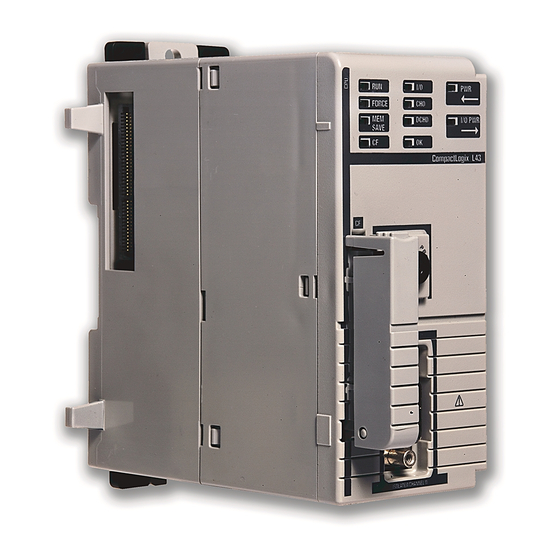
Chapter 1 About the 1768 CompactLogix Controller The 1768-L43 and 1768-L45 CompactLogix controllers combine a 1768 backplane and a 1769 backplane. The 1768 backplane supports the 1768 controller, the 1768 power supply, and a maximum of two 1768 modules, such as the EtherNet/IP module and the SERCOS interface module. -
Page 24: Mount And Wire The Line Interface Module
Chapter 1 Prepare the CompactLogix Hardware Mount and Wire the Line Interface Module 2094-AL75S or Equivalent Hardware, Required for EtherNet/IP and DeviceNet Systems The line interface module (LIM) serves as the power connection and the generation point for the complete power needs of most control panels. The LIM module provides the control of three-phase power and the drive logic power, and also serves as the source and circuit protection of power for the controller, I/O, and other panel devices. -
Page 25: Assemble The 1768 Compactlogix System
Prepare the CompactLogix Hardware Chapter 1 Assemble the 1768 CompactLogix System 1768-L43 Controller, 1768-L45 Controller, 1768-PA3 Power Supply, 1768-ENBT, 1768-M04SE, 1769-SDN, 1769 Local I/O Modules, 1769-ECR End Cap Terminator 1. Mount the 1768-L43 or 1768-L45 controller on the DIN rail. - Page 26 Chapter 1 Prepare the CompactLogix Hardware 3. Mount the SERCOS 1768-M04SE module. a. Pull locking tabs out. b. Align SERCOS module to the left of EtherNet/IP module or controller and slide into place. c. Push locking tabs in. 4. Mount the power supply on the DIN rail.
- Page 27 Prepare the CompactLogix Hardware Chapter 1 6. Mount the 1769-SDN and 1769 I/O modules to the right of the controller on DIN rail. In this quick start, the 1769-SDN module is directly to the right of the controller in slot 1. a.
-
Page 28: Make Ethernet/Ip Network Connection
Chapter 1 Prepare the CompactLogix Hardware Make EtherNet/IP Network Connection 1. Mount the Ethernet Line Interface Module I/O Power switch to the DIN rail. 2. Connect the Ethernet IO_PWR1 IO_COM1 switch power terminals to IO_PWR1 IO_COM1 the I/O power terminals IO_PWR1 IO_COM1 on the front of the line... -
Page 29: Make Devicenet Network Connections
Prepare the CompactLogix Hardware Chapter 1 Make DeviceNet Network Connections 1. Attach and lock the 1606-XLDNET8 DeviceNet power supply to a DIN rail by pressing the tab at the top of the supply. Publication IASIMP-QS003B-EN-P - October 2009... - Page 30 Chapter 1 Prepare the CompactLogix Hardware 2. Assemble the DeviceNet Distributed KwikLink Sealed POINT I/O network cable system KwikLink Sealed Terminator Connection with Terminator using the KwikLink flat 1734-ADN Adapter cable, terminators, and sealed micro connectors for each device. See instructions included KwikLink Sealed PowerFlex 70 Drive Micro Connector...
- Page 31 Prepare the CompactLogix Hardware Chapter 1 WARNING Verify that all incoming power is turned off before wiring power. 7. Wire the DeviceNet power supply to the 230V AC Aux Power Output connector on the line interface module. 8. Place the switch in the L (line) position that matches N (neutral)
-
Page 32: Wire The 1768-Pa3 Power Supply
Chapter 1 Prepare the CompactLogix Hardware Wire the 1768-PA3 Power Supply Required for EtherNet/IP and DeviceNet Systems 1. Wire the 1768-PA3 power supply to the 230V AC Aux Power Output Connector on the line interface module. 2. Do not turn on incoming power. -
Page 33: Additional Resources
Prepare the CompactLogix Hardware Chapter 1 Additional Resources Resource Description CompactLogix Controller Installation Provides details on how to install controller firmware, configure the serial and Instructions, publication 1768-IN004 EtherNet/IP driver, and troubleshoot system power and controller operation. CompactLogix EtherNet/IP Communication Provides details on how to install, configure and troubleshoot the module. - Page 34 Chapter 1 Prepare the CompactLogix Hardware Notes: Publication IASIMP-QS003B-EN-P - October 2009...
-
Page 35: Chapter 2 Introduction
Chapter Prepare the Computer and Load Controller Firmware Introduction In this chapter, you configure network communication on your computer and install the necessary programming and configuration software. Before You Begin • Assemble the CompactLogix hardware (Chapter • Verify that your computer meets the software’s system requirements for your edition of RSLogix 5000 software. -
Page 36: Follow These Steps
Chapter 2 Prepare the Computer and Load Controller Firmware Follow These Steps Complete the appropriate steps. Terminology page 37 Make Network Connections for Personal page 38 Install RSLogix Programming page 39 Configure Serial Driver page 44 Set the IP Address for the Computer page 46 Configure the... -
Page 37: Terminology
Prepare the Computer and Load Controller Firmware Chapter 2 Terminology Ethernet networks use these types of addresses. Term Definition Ethernet Address Each Ethernet device has a unique Ethernet address (sometimes called a MAC address). The address appears as twelve digits separated by colons (for example, xx:xx:xx:xx:xx:xx). It is usually on a label on the device itself. -
Page 38: Make Network Connections For Personal Computer
Chapter 2 Prepare the Computer and Load Controller Firmware Make Network Connections for Personal Computer Network Connections Required for EtherNet/IP System 1. Connect a CAT5 Ethernet cable between the Ethernet port on the computer and the Ethernet switch. Serial 1756-CP3 This connection is used to configure the EtherNet/IP... -
Page 39: Install Rslogix Programming Software
Prepare the Computer and Load Controller Firmware Chapter 2 Install RSLogix Programming Software Required for all controllers Throughout the installation, click Next to use default RSLogix 5000 installation settings except when indicated in the steps below. 1. Begin the RSLogix 5000 software installation. - Page 40 Chapter 2 Prepare the Computer and Load Controller Firmware 5. Accept the license agreement and click Next. 6. Click Next to install the program files to the default directory. 7. Select your activation type and click Next. This quick start uses FactoryTalk Activation software to activate RSLogix...
- Page 41 Prepare the Computer and Load Controller Firmware Chapter 2 10. Click Next to install the typical firmware kits. 11. Click Next to install typical RSLogix Architect tools. 12. Click Next to install the typical set of EDS files and RSLinx software. Publication IASIMP-QS003B-EN-P - October 2009...
- Page 42 Chapter 2 Prepare the Computer and Load Controller Firmware 13. Click Install to complete the installation. The installation dialog box displays progress while the software installs. As the installation progresses, you may be prompted to complete additional set-up tasks depending on your system configuration.
- Page 43 Prepare the Computer and Load Controller Firmware Chapter 2 17. Select your host ID and click Next. The activation completes if the computer is connected to the Internet. If Internet access is not available, call Rockwell Automation Technical Support to complete your activation. 18.
-
Page 44: Configure A Serial Driver
Chapter 2 Prepare the Computer and Load Controller Firmware Configure a Serial Driver Required for all controllers 1. Launch RSLinx software. 2. Under Communications, select Configure Drivers. 3. Select RS-232 DF1 devices. 4. Click Add New. 5. Click OK to keep the default name. - Page 45 Prepare the Computer and Load Controller Firmware Chapter 2 6. Select the Comm Port to which you connected the 1756-CP3 cable. 7. For Device, select Logix5550/CompactLogix. 8. Click Auto Configure. 9. Click OK. The Serial driver is added to the Configured Drivers list.
-
Page 46: Set The Ip Address For The Computer
Chapter 2 Prepare the Computer and Load Controller Firmware Set the IP Address for the Computer Required for all controllers, regardless of network choice 1. On your desktop, right-click My Network Places and select Properties. 2. Double-click the Local Area Connection. - Page 47 Prepare the Computer and Load Controller Firmware Chapter 2 9. Click the Support tab. 10. Verify that the IP Address and Subnet Mask match what you entered on the Appendix A If these numbers do not match what you entered, contact your network administrator to verify that your IP address is correct.
-
Page 48: Configure The Ethernet/Ip Driver In Rslinx Software
Chapter 2 Prepare the Computer and Load Controller Firmware Configure the EtherNet/IP Driver in RSLinx Software Required for 1768-L43, 1768-L45, and PanelView Plus 1. If RSLinx software is not open, launch RSLinx software. From the Communications menu, choose Configure Drivers. -
Page 49: Load The Controller Firmware
Prepare the Computer and Load Controller Firmware Chapter 2 The EtherNet/IP driver is added to the Configured Drivers list. 7. Verify that the driver’s Status is Running, and click Close. Load the Controller Firmware Required for All Systems This procedure shows how to load firmware in the controller using a serial connection. It is faster to load the firmware using an EtherNet/IP connection. - Page 50 Chapter 2 Prepare the Computer and Load Controller Firmware 3. Click Next when the Welcome screen appears. 4. Select the controller catalog number and click Next. 5. Move the keyswitch on controller to Program. 6. If the Current Revision matches the firmware revision you want, click Cancel, then skip to the next section.
- Page 51 Update complete. 18.0 8. Close ControlFlash by clicking Cancel, then Yes. The 1768-L43 and 1768-L45 controllers are compatible with firmware version 16.23, or ATTENTION later. If you encounter errors, contact Technical Support. Publication IASIMP-QS003B-EN-P - October 2009...
-
Page 52: Install Additional Software
Chapter 2 Prepare the Computer and Load Controller Firmware Install Additional Software • If your network configuration includes a PanelView Plus terminal, install FactoryTalk Machine Edition software and RSLinx Enterprise software from the FactoryTalk View Machine Edition package. • If you are using a DeviceNet network, install RSNetWorx for DeviceNet software. Also install the DeviceNet Tag Generator Tool under optional steps of the RSNetWorx for DeviceNet install. -
Page 53: Chapter 3 Introduction
Chapter Prepare the Distributed POINT I/O Hardware Introduction In this chapter, you install the 1734 POINT network adapter and the 1734 POINT I/O modules. Before You Begin • Assemble your CompactLogix hardware (Chapter • Determine which of these network adapters to use: –... -
Page 54: Follow These Steps
Chapter 3 Prepare the Distributed POINT I/O Hardware Follow These Steps If you have POINT I/O, complete the steps for your network. DeviceNet EtherNet/IP DIRTY Mount and Mount and Connect the Connect the L1 L2 L3 E Network Adapter Network Adapter LINE page 56 page 55... -
Page 55: Mount And Connect The Network Adapter
Prepare the Distributed POINT I/O Hardware Chapter 3 Mount and Connect the Network Adapter 1734-AENT EtherNet/IP Adapter for EtherNet/IP System 1. Locate the Ethernet Example Address Address (MAC) and the 00:00:BC:21:44:8A major revision on the Ethernet Address POINT Adapter and record both in Appendix The address is used to set the IP address. - Page 56 Chapter 3 Prepare the Distributed POINT I/O Hardware 1734-ADN DeviceNet Adapter for DeviceNet System 1. Remove the protective cover from the right side of the adapter. 2. Press the adapter onto the DIN rail. 3. Set the node address to 02 for this example.
-
Page 57: Mount The Point I/O Modules
Prepare the Distributed POINT I/O Hardware Chapter 3 Mount the POINT I/O Modules Required for EtherNet/IP and DeviceNet Systems The 1734-IT21 must be mounted in the 1734-TBCJC wiring base. All other IMPORTANT modules can be mounted in either the 1734-TB or 1734-TBS wiring bases. 1. -
Page 58: Mount And Wire The Point I/O Power Supply
Chapter 3 Prepare the Distributed POINT I/O Hardware Mount and Wire the POINT I/O Power Supply 1794-PS3 or 1794-PS13 Power Supply for EtherNet/IP and DeviceNet Systems WARNING Verify that all incoming power is turned off before wiring power. 1. Hook the upper-lip of the power module onto the DIN rail. -
Page 59: Wire The Adapter And I/O Modules To The Power Supply
Prepare the Distributed POINT I/O Hardware Chapter 3 Wire the Adapter and I/O Modules to the Power Supply Required for EtherNet/IP and DeviceNet Systems 1. Connect the 12/24V dc common and power wires from the power supply to the adapter. Refer to the installation instructions for the 1734-AENT or... -
Page 60: Additional Resources
Chapter 3 Prepare the Distributed POINT I/O Hardware Additional Resources Resource Description POINT I/O EtherNet/IP Adapter Installation Provides details regarding installation of the adapter and technical specifications. Instructions, publication 1734-IN590 POINT I/O DeviceNet Adapter Installation Provides details regarding installation of the adapter and technical specifications. Instructions, publication 1734-IN026 POINT I/O Wiring Base Assembly Installation... -
Page 61: Chapter 4 Introduction
Chapter Prepare the PowerFlex 70 Drive Introduction In this chapter, you mount and wire power to a PowerFlex 70 drive. You also configure the communication adapter and make network connections. Before You Begin • Assemble your CompactLogix hardware (Chapter • Determine which network adapter to use on the PowerFlex 70 drive: –... -
Page 62: Follow These Steps
Chapter 4 Prepare the PowerFlex 70 Drive Follow These Steps If you have a PowerFlex 70 Drive, complete the steps for your network. DeviceNet EtherNet/IP DIRTY Mount and Wire Mount and Wire the PowerFlex 70 the PowerFlex 70 L1 L2 L3 E Drive Drive LINE... -
Page 63: Mount And Wire The Powerflex 70 Drive
Prepare the PowerFlex 70 Drive Chapter 4 Mount and Wire the PowerFlex 70 Drive Required for EtherNet/IP and DeviceNet Systems WARNING Verify that all incoming power is turned off before wiring power. 1. Mount the PowerFlex 70 drive to the control enclosure subpanel using the four mounting slots provided. - Page 64 Chapter 4 Prepare the PowerFlex 70 Drive 3. Remove a knockout from the bottom plate on the drive for routing the power line conductors. 4. Wire the PowerFlex 70 240V AC, 3-phase line power terminals to the 240V AC, 3-phase Load connector on the line interface module.
-
Page 65: Configure The Communication Adapter
Prepare the PowerFlex 70 Drive Chapter 4 Configure the Communication Adapter 20-COMM-D DeviceNet Adapter for DeviceNet System 1. Set the node address on the adapter to 13 for this quick start. Tens Ones Digit Digit 2. Set the adapter to AUTO for autobaud. -
Page 66: Connect Communication Adapter To The Powerflex 70 Drive
Chapter 4 Prepare the PowerFlex 70 Drive Connect Communication Adapter to the PowerFlex 70 Drive 20-COMM-D DeviceNet Adapter for DeviceNet System 1. Connect the flat-ribbon cable between the adapter and the PowerFlex 70 drive. 2. Fold the cable under adapter without creasing and secure adapter on drive using the captive screws. - Page 67 Prepare the PowerFlex 70 Drive Chapter 4 20-COMM-E EtherNet/IP Adapter for EtherNet/IP System 1. Connect the flat-ribbon cable between the adapter and the PowerFlex 70 drive. 2. Fold the cable under the adapter without creasing and secure the adapter on the drive using the captive screws.
-
Page 68: Additional Resources
Chapter 4 Prepare the PowerFlex 70 Drive Additional Resources Resource Description PowerFlex 70 User Manual, publication Provides details on how to mount and wire power to the PowerFlex 70 drive. Also 20A-UM001 provides information on how to set drive parameters and troubleshoot the drive. PowerFlex 70 EtherNet/IP Adapter User Provides details on how to install, configure, and use the adapter. -
Page 69: Chapter 5 Introduction
Chapter Prepare the PanelView Plus Terminal Introduction In this chapter, you mount and wire the PanelView Plus terminal. You also configure network communication and make network connections. Before You Begin • Assemble your CompactLogix hardware (Chapter • Determine which network to use. –... -
Page 70: Follow These Steps
Chapter 5 Prepare the PanelView Plus Terminal Follow These Steps If you have a PanelView Plus terminal, complete the appropriate steps. EtherNet/IP DeviceNet Mount and Wire Mount and Wire the PanelView the PanelView Plus Terminal Plus Terminal page 71 page 71 Make Network Make Network Connections for... -
Page 71: Mount And Wire The Panelview Plus Terminal
Prepare the PanelView Plus Terminal Chapter 5 Mount and Wire the PanelView Plus Terminal Required for EtherNet/IP and DeviceNet Systems For the purpose of this quick start, the PanelView Plus terminal can be propped on a desktop. For complete mounting instructions, refer to the PanelView Plus Terminal user manual, publication 2711P-UM001. -
Page 72: Make Network Connections For Panelview Plus
Chapter 5 Prepare the PanelView Plus Terminal Make Network Connections for PanelView Plus Network Connections Required for EtherNet/IP System Connect a CAT5 Ethernet cable between the Ethernet port on the PanelView Plus terminal and the Ethernet switch. CAT5 Ethernet Cable Network Connections Required for DeviceNet System Connect the 2711-NC13 cable between the serial port... -
Page 73: Assign Ip Address For Panelview Plus
Prepare the PanelView Plus Terminal Chapter 5 Assign IP Address for PanelView Plus Required for EtherNet/IP System 1. Apply power to the PanelView terminal. 2. On the initial PanelView configuration screen, select Terminal Settings [F4]. 3. Navigate to Built-in Ethernet Diagnostics Setup Display Controller by selecting... - Page 74 Chapter 5 Prepare the PanelView Plus Terminal 5. Select Use DHCP [F4] to select No. 6. Select IP Address [F1]. a. Enter an IP address in the input panel. b. Press Enter. c. Record IP address in Appendix A. For information on IP addresses, see page 7.
-
Page 75: Upgrade Terminal Firmware
Prepare the PanelView Plus Terminal Chapter 5 9. Select Close [F8] until you return to the initial configuration screen. 10. Select Reset [F8] to reset the terminal, then Yes [F7] to confirm. Upgrade Terminal Firmware Required for Terminals with Firmware Earlier than 4.00.09 If the firmware in your PanelView Plus terminal is earlier than 4.00.09, you need to upgrade the terminal firmware. -
Page 76: Additional Resources
Chapter 5 Prepare the PanelView Plus Terminal Additional Resources Resource Description PanelView Plus Terminal User Manual, Provides details on how to install communication modules, mount the PanelView Plus publication 2711P-UM001 terminals, wire power to the terminals, make network connections, and configure terminal settings. -
Page 77: Chapter 6 Introduction
Chapter Prepare the Kinetix 6000 Multi-axis Servo Drive System Introduction In this chapter, you prepare your Kinetix 6000 Multi-axis Servo Drive system. Before You Begin • Assemble your CompactLogix Hardware (Chapter • Review Basic System Components (Preface) What You Need •... -
Page 78: Follow These Steps
Chapter 6 Prepare the Kinetix 6000 Multi-axis Servo Drive System Follow These Steps If you have a Kinetix 6000 Multi-axis Servo Drive System, complete these steps. DIRTY Mount and Bond the Power Rail L1 L2 L3 E LINE page 79 AC Line Filter Line Interface... -
Page 79: Mount And Bond The Power Rail
Prepare the Kinetix 6000 Multi-axis Servo Drive System Chapter 6 Mount and Bond the Power Rail 2094-PRS1 through 2094-PRS8 The Kinetix power rails support one integrated axis module (IAM), and up to seven axis modules (AM), or shunt modules (SM). The connector pins for each slot on the power rail are covered by a protective boot. -
Page 80: Mount The Integrated Axis And Axis Module
Chapter 6 Prepare the Kinetix 6000 Multi-axis Servo Drive System Mount the Integrated Axis and Axis Module 2094-AC09-M02, 2094-AM01 The integrated axis module (IAM) mounts in the two leftmost slots of the power rail. The axis modules (AM) mount to the right of the IAM module in left-to-right order, ranging from highest-to-lowest power rating. - Page 81 Prepare the Kinetix 6000 Multi-axis Servo Drive System Chapter 6 6. Use 2.26 Nm (20 lb•in) torque to tighten the mounting screws. Mounting Screws on IAM and AM modules. 7. Remove the protective boot from the power rail slot to the right of the IAM module.
-
Page 82: Wire Power To The Integrated Axis Module
Chapter 6 Prepare the Kinetix 6000 Multi-axis Servo Drive System Wire Power to the Integrated Axis Module This procedure shows power connections to the integrated axis module (IAM) when using the line interface module (LIM). The AC conductor sizes are based on the motor load requirements. -
Page 83: Wire Servo Motors To Integrated Axis And Axis Modules
Prepare the Kinetix 6000 Multi-axis Servo Drive System Chapter 6 Wire Servo Motors to Integrated Axis and Axis Modules 2094-AC09-M02, 2094-AM01, MPL-A310P-MK22AA, 2090-XXNPMP-16S03, 2090-UXNFBMP-S03 1. Attach motor power Integrated Axis Module or Axis Module cable to shield clamp. Front View Top View a. -
Page 84: Connect The Sercos Fiber Optic Cables
Chapter 6 Prepare the Kinetix 6000 Multi-axis Servo Drive System Connect the SERCOS Fiber Optic Cables 2090-SCEP0-1, 2090-SCEP0-9 SERCOS Interface Module 1. Connect the SERVO 2090-SCEP0-9 fiber optic Interface cable between the TX port on the bottom of the SERCOS module and the RX port on the IAM module, making sure to tighten the fiber optic... -
Page 85: Set The Sercos Node Address
Prepare the Kinetix 6000 Multi-axis Servo Drive System Chapter 6 Set the SERCOS Node Address 1. Set the SERCOS node address on the front of the Integrated Axis Module to 01. 2. Record this address in Appendix Publication IASIMP-QS003B-EN-P - October 2009... -
Page 86: Additional Resources
Chapter 6 Prepare the Kinetix 6000 Multi-axis Servo Drive System Additional Resources Resource Description Kinetix Motion Control Selection Guide, Provides details on motor and drive performance specifications. publication GMC-SG001 Kinetix 6000 Multi-Axis Servo Drive Installation Provides details on panel layout, and how to install and wire Kinetix 6000 drives and Manual, publication 2094-IN001 components. -
Page 87: Chapter 7 Introduction
Chapter Configure the EtherNet/IP Network Introduction In this chapter, you assign IP addresses to devices on the EtherNet/IP network. Before You Begin • Assemble your CompactLogix hardware (Chapter • Prepare your computer (Chapter Devices on the EtherNet/IP network broadcast requests for IP addresses until the IP addresses have been assigned. The procedure in this chapter uses the BOOTP Server packaged with RSLogix 5000 software to assign IP addresses, however, any industry-standard BOOTP server will work. -
Page 88: Follow These Steps
Chapter 7 Configure the EtherNet/IP Network Follow These Steps If you have an EtherNet/IP network, complete these steps. Assign IP Addresses page 89 Browse the EtherNet/IP Network in RSLinx Classic Software page 91 Terminology Ethernet networks use these types of addresses. Term Definition Ethernet address... -
Page 89: Assign Ip Addresses
Configure the EtherNet/IP Network Chapter 7 Assign IP Addresses The BOOTP/DHCP Server utility is used to assign IP addresses to most devices in this quick start, except the PanelView Plus terminal. The IP address for the PanelView Plus device was assigned during installation in Chapter 5, Prepare the PanelView Plus terminal. - Page 90 Chapter 7 Configure the EtherNet/IP Network The Request History displays all devices in your network that need IP addresses. The Ethernet (MAC) addresses correspond to the addresses entered in Appendix 5. Double-click a request from one of the devices. 6. Enter the IP address that you recorded in Appendix A and click...
-
Page 91: Browse The Ethernet/Ip Network In Rslinx Classic Software
Configure the EtherNet/IP Network Chapter 7 9. Repeat step 8 for all devices except the PanelView Plus terminal. 10. Close the BOOTP/DHCP utility. If prompted to save changes, click No. Browse the EtherNet/IP Network in RSLinx Classic Software Click the RSWho button to view the EtherNet/IP driver and devices. -
Page 92: Additional Resources
Chapter 7 Configure the EtherNet/IP Network Additional Resources Resource Description EtherNet/IP Modules in Logix 5000 Control Provides details on how to configure and use EtherNet/IP modules in Logix 5000 Systems User Manual, publication ENET-UM001 systems including how to assign IP addresses to devices and browse the EtherNet/IP network in RSLinx software. -
Page 93: Chapter 8 Introduction
Chapter Configure the DeviceNet Network Introduction In this chapter, you configure the DeviceNet node address for the 1769-SDN module. You also create the RSNetWorx for DeviceNet file that stores the network configuration. Before You Begin • Install all hardware, including the DeviceNet Scanner (Chapter 1 through 6). -
Page 94: Follow These Steps
Chapter 8 Configure the DeviceNet Network Follow These Steps If you have a DeviceNet network, complete these steps. Apply Power to the DeviceNet Network page 94 Set the Node Address of the DeviceNet Scanner page 95 Create a DeviceNet Configuration File page 97 Apply Power to the DeviceNet Network Turn on incoming power to... -
Page 95: Set The Node Address Of The Devicenet Scanner
Configure the DeviceNet Network Chapter 8 Set the Node Address of the DeviceNet Scanner 1. Launch RSNetWorx for DeviceNet software. 2. Select Tools>Node Commissioning. 3. Click Browse. 4. Under AB_DF1-1, expand the CompactLogix Backplane and the 1769 CompactBus. 5. Expand the 1769-SDN Scanner Module and the DeviceNet Port, then select 1769-SDN Scanner... - Page 96 Chapter 8 Configure the DeviceNet Network 7. If you receive a linking device warning, click Yes. The Node Commissioning dialog box is populated with the current settings for the 1769-SDN module. 8. Select an available node Address for the 1769-SDN module and click Apply.
-
Page 97: Create A Devicenet Configuration File
Chapter 8 Create a DeviceNet Configuration File 1. Select File>New. 2. Click the Who Active button to go online. 3. Under AB_DF-1, expand the 1768-L43 Backplane and the 1769 CompactBus. 4. Expand the 1769-SDN Scanner Module and select the DeviceNet port, then click OK. - Page 98 Chapter 8 Configure the DeviceNet Network 6. Click OK. RSNetWorx begins browsing the network. When all of the devices on your DeviceNet network have appeared on the screen, click Cancel. If your PowerFlex drive does not display, see Uploading an EDS File From a Drive, Knowledgebase ID 20539.
- Page 99 Configure the DeviceNet Network Chapter 8 10. In the Platform field, select CompactLogix. 11. Select the Slot number, recorded in Appendix A and click OK. 12. Save the DeviceNet configuration file. 13. Record the .dnt file name and path in Appendix 14.
-
Page 100: Additional Resources
Chapter 8 Configure the DeviceNet Network Additional Resources Resource Description DeviceNet Modules in Logix5000 Control Provides details on the installation, configuration, and operation of DeviceNet Systems User Manual, publication DNET-UM004 modules. Uploading an EDS File From a Drive, Provides an explanation about uploading EDS files from drives. Knowledgebase ID 20539, http://rockwellautomation.com/knowledgebase Publication IASIMP-QS003B-EN-P - October 2009... -
Page 101: Chapter 9 Introduction
Chapter Create a Project in RSLogix 5000 Programming Software Introduction In this chapter, you create a project in RSLogix 5000 programming software. In the project, you use ladder logic to create a push button that controls a light on a digital output module. This project is used in subsequent chapters to test communication with other devices. -
Page 102: Follow These Steps
Chapter 9 Create a Project in RSLogix 5000 Programming Software Follow These Steps Complete the appropriate steps depending on your network. Create a Project page 103 Configure Optional 1768-ENBT Complete if you have an Ethernet Ethernet Module System page 104 Configure Optional 1769-SDN... -
Page 103: Create A Project
Create a Project in RSLogix 5000 Programming Software Chapter 9 Create a Project Required for EtherNet/IP and DeviceNet Systems 1. Launch RSLogix 5000 programming software. 2. Select New Project. 3. In the New Controller dialog box: a. Select the controller Type and Revision. -
Page 104: Configure 1768-Enbt Ethernet Module
Chapter 9 Create a Project in RSLogix 5000 Programming Software Configure 1768-ENBT Ethernet Module Required for EtherNet/IP System 1. Under I/O Configuration, right-click 1768 Bus and select New Module. 2. Expand Communications, select 1768-ENBT/A, and click 3. In the New Module dialog box: a. -
Page 105: Configure 1769-Sdn Devicenet Module
Create a Project in RSLogix 5000 Programming Software Chapter 9 Configure 1769-SDN DeviceNet Module Required for DeviceNet System 1. Under I/O Configuration, right-click 1769 Bus, and select New Module. 2. Expand Communications, select the 1769-SDN series letter recorded in Appendix A, and click 3. - Page 106 Chapter 9 Create a Project in RSLogix 5000 Programming Software 4. In the New Module dialog box: a. Enter a Name for the module. b. Set the Slot to 1. c. Select the minor (firmware) Revision. d. Select an Input Size and Output Size to accommodate the input and output sizes of the...
-
Page 107: Configure 1769 Local I/O Modules
Create a Project in RSLogix 5000 Programming Software Chapter 9 Configure 1769 Local I/O Modules Required for EtherNet/IP and DeviceNet Systems 1. Under I/O Configuration, right-click 1769 Bus, and select New Module. 2. Expand Digital, select the leftmost I/O module, and click OK. -
Page 108: Verify I/O Configuration
Chapter 9 Create a Project in RSLogix 5000 Programming Software 3. In the dialog box: a. Enter a Name for the module. b. Set the appropriate Slot number. c. Click Change. d. Select Disable Keying. e. Click OK to accept module definition changes, then OK to exit dialog box. -
Page 109: Add Ladder Logic To Test Local 1769 Compact I/O Modules
Create a Project in RSLogix 5000 Programming Software Chapter 9 Add Ladder Logic to Test Local 1769 Compact I/O Modules Required for EtherNet/IP and DeviceNet Systems 1. Expand Tasks and double-click MainRoutine under MainProgram. A blank MainRoutine opens. 2. From the Element toolbar, drag and drop an Examine On and an Output Energize element... - Page 110 Chapter 9 Create a Project in RSLogix 5000 Programming Software 5. Right-click PB and select New ‘PB’. 6. Click OK to accept the defaults. 7. Name the Output Energize xxxx_Light, where xxxx is the catalog number suffix of the 1769 Compact digital output module.
- Page 111 Create a Project in RSLogix 5000 Programming Software Chapter 9 8. Right-click the xxxx_Light tag name and select New ‘xxxx_Light’. The xxxx_Light is an alias tag for the I/O point tag name. This lets you assign a simple name to a physical I/O point address.
-
Page 112: Set The Project Path And Download To The Controller
Chapter 9 Create a Project in RSLogix 5000 Programming Software Set the Project Path and Download to the Controller Required for EtherNet/IP and DeviceNet Systems 1. Save your changes. 2. Move the keyswitch on controller to Program. 3. Click the Who Active button. - Page 113 Create a Project in RSLogix 5000 Programming Software Chapter 9 7. Click Download. The project Path updates. EtherNet/IP Serial 8. Move the keyswitch on controller to Run. 9. Select the PB examine on instruction and press Ctrl+T to toggle the state from 0 to 1, or off to on.
-
Page 114: Additional Resources
Chapter 9 Create a Project in RSLogix 5000 Programming Software Additional Resources Resource Description Logix5000 Controllers Common Procedures Provides details about creating and editing a program, communicating with modules, Programming Manual, publication 1756-PM001 and configuring modules. DeviceNet Modules in Logix 5000 Control Provides information on the installation, configuration, and operation of DeviceNet Systems User Manual, publication modules. -
Page 115: Chapter 10 Introduction
Chapter Add Distributed Point I/O Modules to the Project Introduction In this chapter, you add distributed POINT I/O modules to your RSLogix 5000 project. You also add ladder logic and download the project to the controller so you can test communication with an I/O module. -
Page 116: Follow These Steps
Chapter 10 Add Distributed Point I/O Modules to the Project Follow These Steps If you have distributed POINT I/O modules, complete these steps. EtherNet/IP DeviceNet Configure the Add Distributed DeviceNet I/O Modules Subnet page 120 page 117 Configure the Add Ladder 1734-ADN Logic Properties... -
Page 117: Add Distributed I/O Modules
Add Distributed Point I/O Modules to the Project Chapter 10 Add Distributed I/O Modules Required for EtherNet/IP System 1. Verify that your project is offline. 2. Right-click 1768-ENBT under 1768-Bus and select New Module. 3. Expand Communications. 4. Select the 1734-AENT adapter and click OK. - Page 118 Chapter 10 Add Distributed Point I/O Modules to the Project 6. In the New Module dialog box: a. Enter a Name for the adapter. b. Enter the IP Address recorded in Appendix c. Select the Chassis Size, which is the exact number of POINT I/O modules plus one for the adapter.
- Page 119 Add Distributed Point I/O Modules to the Project Chapter 10 8. Expand Digital, select the catalog number of the leftmost POINT I/O module in chassis, and click OK. 9. In the New Module dialog box: a. Enter a Name for the module.
-
Page 120: Configure The Devicenet Subnet
Chapter 10 Add Distributed Point I/O Modules to the Project Configure the DeviceNet Subnet Required for DeviceNet System 1. Launch RSNetWorx for DeviceNet. 2. Select File>New. 3. Click the Who Active button and go online. 4. Under AB _DF1, DF1, select DeviceNet Subnet under 1734-ADN, and click OK. - Page 121 Add Distributed Point I/O Modules to the Project Chapter 10 5. Click OK. RSNetWorx browses the network. When all devices on your POINT I/O subnet appear, click Cancel. 6. Select Network> Upload from Network. 7. Click Yes. The configuration is uploaded, synching the software and the device.
- Page 122 Chapter 10 Add Distributed Point I/O Modules to the Project 9. Click the Device Bridging tab. 10. Click Associate File. 11. Select the DeviceNet.dnt configuration file. Click Open. 12. Click Apply, then OK. 13. Click Save. 14. Enter a File name that identifies this file as the subnet and click Save.
-
Page 123: Configure The 1734-Adn Properties
Add Distributed Point I/O Modules to the Project Chapter 10 Configure the 1734-ADN Properties Required for DeviceNet System 1. Select File>Open. 2. Select the DeviceNet.dnt file and click Open. 3. Click the Who Active button to go online. 4. Click OK and RSNetWorx will browse the network. - Page 124 Chapter 10 Add Distributed Point I/O Modules to the Project 6. Right-click 1734-ADN and select Properties. 7. On the Device Bridging tab, click Associate File. 8. Select the subnet file and click Open. 9. Click Apply. 10. Select the Parameters tab. 11.
- Page 125 Add Distributed Point I/O Modules to the Project Chapter 10 12. Set the AutoAddress Backplane Modules Parameter to 1. 13. Change the Auto Start Mode to Map Data to DWord Boundaries. 14. Click Apply. 15. Click Yes to download the configuration to device.
-
Page 126: Create A Devicenet Scanlist
Chapter 10 Add Distributed Point I/O Modules to the Project Create a DeviceNet Scanlist Go Online. Required for DeviceNet System 1. Right-click the 1769-SDN module and select Properties. 2. Select the Scanlist tab. 3. Click Upload to upload configuration from the device. - Page 127 Add Distributed Point I/O Modules to the Project Chapter 10 6. Click Yes. 7. Click OK. 8. Save the DeviceNet configuration file. You will use this file to Create DeviceNet Tags, and then Add Ladder Logic, later in this chapter. 9.
-
Page 128: Add Ladder Logic
Chapter 10 Add Distributed Point I/O Modules to the Project Add Ladder Logic Required for EtherNet/IP System 1. Under Tasks, double-click MainRoutine. 2. Drag and drop a Branch onto rung 0. 3. Expand the Branch to the right side of the xxxx_Light. - Page 129 Add Distributed Point I/O Modules to the Project Chapter 10 5. Right-click the Light and select New ‘xxxx_Light’. 6. In the Type field, select Alias. 7. In the Alias For field, browse for the recorded address below. Select this Address Example From _______...
-
Page 130: Create Devicenet Tags And Add Ladder Logic
Chapter 10 Add Distributed Point I/O Modules to the Project Create DeviceNet Tags and Add Ladder Logic Required for DeviceNet System 1. Launch RSLogix 5000 programming software, if not open, and select the current controller project. This example uses My_L43_Controller. 2. - Page 131 Add Distributed Point I/O Modules to the Project Chapter 10 5. Click Select RSNetWorx Project, then select the DeviceNet.dnt file entered in Appendix 6. Click Select Scanner Node, then select the node of the 1769-SDN scanner entered in Appendix 7. Click Step 5, Generate Tags.
- Page 132 Chapter 10 Add Distributed Point I/O Modules to the Project When tag generation is complete, the results display. 10. Close the DeviceNet Tag Generator. Note that the new programs and tags have been added to the controller organizer. These tasks were created by the Tag Generator.
- Page 133 Add Distributed Point I/O Modules to the Project Chapter 10 13. Expand the branch to the right side of the xxxx_Light. 14. Drag and drop another Output Energize element onto the branch and name it xxxx_Light, where xxxx is the suffix of the catalog number of the digital 1734 POINT output module.
- Page 134 Chapter 10 Add Distributed Point I/O Modules to the Project 19. Click OK. 20. Double-click End to add another rung. 21. Drag and drop an Output Energize element onto the branch. 22. Double-click the ?, select the drop-down arrow, then select the Local:X:O. CommandRegister.Run tag, where X is the slot of the 1769-SDN, entered in...
-
Page 135: Download The Project
Add Distributed Point I/O Modules to the Project Chapter 10 Download the Project Required for EtherNet/IP and DeviceNet Systems 1. Save your changes. 2. Move the keyswitch on controller to Program. 3. Click the Controller Status icon and select Download. 4. -
Page 136: Test The Distributed I/O Light
Chapter 10 Add Distributed Point I/O Modules to the Project Test the Distributed I/O Light Required for EtherNet/IP and DeviceNet Systems 1. Move the keyswitch on controller to Run. 2. Select PB and press Ctrl+T to toggle the state from 0 to 1, or off to on. 3. -
Page 137: Introduction
Chapter Create a PowerFlex 70 Application Introduction In this chapter, you configure a PowerFlex 70 drive and add the drive to your RSLogix 5000 project. You also download the project to the controller so you can test communication with the drive. Before You Begin •... -
Page 138: Follow These Steps
Chapter 11 Create a PowerFlex 70 Application Follow These Steps If you have a PowerFlex 70 Drive, complete the appropriate steps. EtherNet/IP DeviceNet Add the Drive to Create a DeviceNet Your RSLogix 5000 Scanlist Project page 139 page 145 Edit the Drive Create Parameters DeviceNet Tags... -
Page 139: Add The Drive To Your Rslogix 5000 Project
Create a PowerFlex 70 Application Chapter 11 Add the Drive to Your RSLogix 5000 Project Required for EtherNet/IP System 1. Move the controller keyswitch to Program. 2. Launch RSLogix 5000 programming software if not open. 3. Open the project offline. 4. - Page 140 Chapter 11 Create a PowerFlex 70 Application 7. In the New Module dialog box: a. Enter a unique Name for the drive. b. Enter the IP address for the PowerFlex 70 that you recorded in Appendix c. Click Change. 8. On the Full or Partial Match dialog box, make sure the Include I/O box is unchecked and click...
- Page 141 Create a PowerFlex 70 Application Chapter 11 11. Download and put the controller in Remote Run mode. 12. Right-click the PowerFlex 70 drive and select Properties. 13. Click the Drive tab. 14. Click Connect to Drive. 15. Select the PowerFlex 70 drive and click OK.
- Page 142 Chapter 11 Create a PowerFlex 70 Application A drive database is created. After the drive database creation is completed, the drive status will change to connected. Continue to the next section to edit the drive parameters. Publication IASIMP-QS003B-EN-P - October 2009...
-
Page 143: Edit The Drive Parameters
Create a PowerFlex 70 Application Chapter 11 Edit the Drive Parameters Required for EtherNet/IP System 1. Double-click the Parameter List. 2. Enter the following parameters: Parameter Name Value Parameter 61 Autotune Ready Parameter 90 Speed Ref A Sel DPI Port 5 Parameter 361 Digital In1 Sel Not Used... - Page 144 Chapter 11 Create a PowerFlex 70 Application 4. From the Parameter Group pull-down list, select Communication >Datalinks. 5. Verify that parameters 300 through 317 are set to 0. 6. Click Close, then OK. The parameters are loaded to the drive. For EtherNet/IP systems, skip to page...
-
Page 145: Create A Devicenet Scanlist
Create a PowerFlex 70 Application Chapter 11 Create a DeviceNet Scanlist Required for DeviceNet System 1. Move the controller keyswitch to Program and go offline. 2. If RSNetWorx for DeviceNet is open, skip to step 3. If RSNetWorx for DeviceNet is not open: a. - Page 146 Chapter 11 Create a PowerFlex 70 Application 5. When all of the devices in your DeviceNet network have appeared, you can click Cancel. 6. Right-click PowerFlex 70 and select Download to Device. 7. Click Yes. The configuration is downloaded to the PowerFlex 70.
- Page 147 Create a PowerFlex 70 Application Chapter 11 11. Change #90, Speed Ref A Sel, to DPI Port 5. This configures the drive to use the speed reference from the network. 12. Verify that #300–317, Datalinks, are set to 0. 13. Verify that #361–366, Digital In# Sel, to Not Used.
- Page 148 Chapter 11 Create a PowerFlex 70 Application 17. Select the Scanlist tab. 18. Click Upload. The configuration is uploaded from the 1769-SDN. 19. Select the PowerFlex 70 and move it to the Scanlist. 20. Verify that Automap on Add is checked and click Apply.
-
Page 149: Create Devicenet Tags
Create a PowerFlex 70 Application Chapter 11 Create DeviceNet Tags Required for DeviceNet System 1. Switch the controller to Program mode. 2. In RSLogix 5000 software, choose Tools>DeviceNet Tag Generator. 3. Select the RSLogix 5000 project you are creating tags for. 4. - Page 150 Chapter 11 Create a PowerFlex 70 Application 5. Click Select RSNetWorx Project then select the DeviceNet.dnt file entered in Appendix 6. Click Select Scanner Node, then select the node of the 1769-SDN scanner entered in Appendix 7. Click Step 5, Generate Tags.
- Page 151 Create a PowerFlex 70 Application Chapter 11 10. Close the DeviceNet Tag Generator. Note that the new programs and tags have been added to the controller organizer. These tasks were created by the Tag Generator. Publication IASIMP-QS003B-EN-P - October 2009...
-
Page 152: Download The Project
Chapter 11 Create a PowerFlex 70 Application Download the Project Required for DeviceNet Systems If you receive a fault message on your PowerFlex 70, press on the keypad to clear the fault. 1. If you have not already done so, move the keyswitch on your controller to Program. -
Page 153: Test The Powerflex 70 Tags
Create a PowerFlex 70 Application Chapter 11 Test the PowerFlex 70 Tags To change the value of a tag in RSLogix software: 1. Select the tag value. 2. Enter or select the desired value. 3. Press Enter. Required for EtherNet/IP System 1. - Page 154 Chapter 11 Create a PowerFlex 70 Application 5. Change ClearFault tag back to 0 and press Enter. 6. Verify that the I.DriveStatus_Ready tag value is 1, indicating that the drive is ready. 7. Change the O.CommandedFreq tag 32767 -------- - -------------- to 15000 engineering units and press Enter.
- Page 155 Create a PowerFlex 70 Application Chapter 11 10. Change the Stop tag to 1. The display on the drive will show a speed decrease until the drive reaches 0.00 Hz. 11. Change the Stop tag back to 0. 12. Go Offline and save. By starting and stopping the drive, you verified: •...
- Page 156 Chapter 11 Create a PowerFlex 70 Application Required for DeviceNet Systems 1. Move the controller keyswitch to Run. 2. Double-click Controller Tags. 3. On the Monitor Tags tab, expand the local output tag that corresponds to your scanner slot. 4. Verify that the CommandRegister.Run tag is set to 1.
- Page 157 Create a PowerFlex 70 Application Chapter 11 5. Expand the output polling tag that corresponds to your DeviceNet scanner. 6. Change the O.Reference tag value to 15000 engineering units, which is approximately 59.5 Hz. This is the speed your 32767 drive will accelerate to -------- - --------------...
- Page 158 Chapter 11 Create a PowerFlex 70 Application WARNING If there is a motor attached to your drive, completing the next step will cause it to turn. 8. Change the O.Start tag to The display on the drive registers the speed increase in Hz until the value at the reference tag is reached.
-
Page 159: Additional Resources
Create a PowerFlex 70 Application Chapter 11 By starting and stopping the drive, you verified: • the controller is correctly communicating with the drive. • the drive can receive simple commands. Additional Resources Resource Description PowerFlex 70 Adjustable Frequency AC Drive Provides details on how to install, configure, and troubleshoot the PowerFlex 70 drive. - Page 160 Chapter 11 Create a PowerFlex 70 Application Notes: Publication IASIMP-QS003B-EN-P - October 2009...
-
Page 161: Introduction
Chapter Create a PanelView Plus Application Introduction In chapter 9, you used ladder logic in RSLogix 5000 programming software to create a push button that controlled an status indicator on a digital output module. In this chapter, you use FactoryTalk View Machine Edition software to create an application with a push button and a multistate indicator that uses that ladder logic. -
Page 162: Follow These Steps
Chapter 12 Create a PanelView Plus Application Follow These Steps If you have a PanelView Plus terminal, complete the appropriate steps. Create a New Application page 163 Create an RSLinx Enterprise Configuration in FactoryTalkView ME page 164 Create Device Shortcuts to the Controller Assign Keys page 166... -
Page 163: Create A New Application
Create a PanelView Plus Application Chapter 12 Create a New Application All controllers 1. Launch FactoryTalkView Studio software. 2. Select the New tab. 3. In the Application Name field, type a name (do not use spaces) and click Create. Publication IASIMP-QS003B-EN-P - October 2009... -
Page 164: Factorytalkview Me
Chapter 12 Create a PanelView Plus Application Create an RSLinx Enterprise Configuration in FactoryTalkView ME All controllers 1. In the FactoryTalkView organizer, expand RSLinx Enterprise and double-click Communication Setup. 2. Click Finish. RSLinx Enterprise software opens. Publication IASIMP-QS003B-EN-P - October 2009... - Page 165 Create a PanelView Plus Application Chapter 12 The Local tab defines the path from the computer to the controller. The Target tab defines the path from the PanelView Plus terminal to the controller. Local Target Terminal Controller Computer The computer needs to The PanelView Plus terminal communicate with the also needs to communicate...
-
Page 166: Create Device Shortcuts To The Controller
Chapter 12 Create a PanelView Plus Application Create Device Shortcuts to the Controller EtherNet/IP Shortcut 1. Expand the EtherNet/IP tree, select your controller and click Add. 2. Enter a shortcut name and click Apply. Do not use spaces in the name. - Page 167 Create a PanelView Plus Application Chapter 12 5. Select the Target tab to view the path from the PanelView terminal to the controller. 6. Click the shortcut and verify that your controller is highlighted. 7. Click OK. 8. Skip to Create the OB16_Light Indicator on page 170.
- Page 168 Chapter 12 Create a PanelView Plus Application Serial Shortcut Before you add the serial drive in this procedure, you must stop and delete the serial driver in RSLinx Classic IMPORTANT software. Depending on the messages that appear, you might have to take all programming and configuration software offline and completely shutdown RSLinx Classic software.
- Page 169 Create a PanelView Plus Application Chapter 12 6. Expand the Backplane tree, select your controller, and click Add. 7. Enter a shortcut name and click Apply. Do not use spaces in the name. 8. Click Copy. 9. Click Yes. 10. Select the Target tab to view the path from the PanelView terminal to the controller.
-
Page 170: Create The Ob16_Light Indicator
Chapter 12 Create a PanelView Plus Application Create the OB16_Light Indicator 1. In FactoryTalk ME software, under Graphics, right-click Displays and select New. 2. Select Objects>Indicator> Multistate. 3. Click and drag to create the indicator. 4. Right-click and select Properties. The Multistate Indicator Properties dialog box opens... - Page 171 Create a PanelView Plus Application Chapter 12 5. On the General tab, select 2 for the Number of states. 6. On the States tab, verify that State0 is selected. 7. In the Caption area, type Light is OFF. 8. Select State1. 9.
- Page 172 Chapter 12 Create a PanelView Plus Application 12. On the Connections tab, click ... under Tag. 13. Right-click your project and select Refresh All Folders. 14. Expand the controller shortcut and select Online>Programs:Main Program. 15. Select ‘xxxx_Light’ (the name of your light in ladder logic) and click The Indicator tag is populated.
-
Page 173: Create A Push Button
Create a PanelView Plus Application Chapter 12 Create a Push Button 1. Select Objects>Push Button>Maintained. 2. Click and drag to create the push button beneath the indicator. 3. Right-click the push button just created and select Properties. 4. On the States tab, verify that State0 is selected. - Page 174 Chapter 12 Create a PanelView Plus Application 6. Select State1. 7. In the Caption, type Push to turn light OFF. 8. Select the Connections tab. 9. In the Value row, click ... under Tag. 10. Expand your controller shortcut and select Online>Program:Main Program.
-
Page 175: Test The Indicator And Push Button
Create a PanelView Plus Application Chapter 12 Test the Indicator and Push Button 1. Verify that the keyswitch on controller is set to Run. 2. Right-click an unused area of the display and select Display Settings. 3. Change the Maximum Tag Update Rate to 0.05. -
Page 176: Add A Goto Configuration Mode Button
Chapter 12 Create a PanelView Plus Application Add a Goto Configuration Mode Button 1. Select Objects>Advanced>Got o Configure Mode. 2. Click and drag to create the Goto button next to the push button. 3. Right-click the push button and select Properties. -
Page 177: Assign Keys
Create a PanelView Plus Application Chapter 12 Assign Keys For PanelView Plus Terminals without a Touch Screen If your PanelView Plus terminal does not have a touch screen, you must assign function keys to the display buttons. If your PanelView Plus does have a touch screen, you can skip this section. -
Page 178: Assign An Initial Screen
Chapter 12 Create a PanelView Plus Application 6. Click OK. 7. Add the function key names to the button captions for both states of the indicator. 8. Save your changes. Assign an Initial Screen 1. Under System, double-click Startup. 2. Check the Initial graphic checkbox and select test_logic. -
Page 179: Transfer The Application To The Panelview Plus Terminal
Create a PanelView Plus Application Chapter 12 Transfer the Application to the PanelView Plus Terminal 1. Select Application>Create Runtime Application. 2. In Save as type, select the Runtime versions that matches your PanelView Plus firmware. To check the PanelView Plus firmware revision, on the terminal, select Terminal Settings [F4]>System... - Page 180 Chapter 12 Create a PanelView Plus Application 5. Click the ... button, select the .mer file just created, then click Open. 6. Verify that the Run application when download completes and the Replace communications checkboxes are checked and verify that your PanelView Plus terminal is selected as the destination terminal.
-
Page 181: Test The Application On The Panelview Plus Terminal
Create a PanelView Plus Application Chapter 12 Test the Application on the PanelView Plus Terminal 1. On the PanelView Plus terminal, press the Load Application [F1]. 2. Select your .mer file and press Load [F2]. 3. Press Yes [F7]. 4. After the application loads, press Run Application [F2]. -
Page 182: Additional Resources
Chapter 12 Create a PanelView Plus Application Additional Resources Resource Description PanelView Plus Terminal User Manual, Provides details on how to install and operate the PanelView Plus terminal. It also publication 2711P-UM001 provides information how to use configuration mode to modify terminal settings, load and run applications. -
Page 183: Introduction
Chapter Create a Kinetix 6000 Application Introduction In this chapter, you configure, download, and test your RSLogix 5000/Kinetix 6000 application. Before You Begin • Prepare your CompactLogix hardware (Chapter • Prepare your computer (Chapter • Prepare your Kinetix 6000 hardware (Chapter What You Need •... -
Page 184: Follow These Steps
Chapter 13 Create a Kinetix 6000 Application Follow These Steps Complete these steps to configure, download, and test your RSLogix 5000/Kinetix 6000 application. Enable Coordinated System Time Master page 185 Create the Motion Group page 186 Enable Coordinated System Time Master page 187 Configure Your Kinetix IAM and AM Modules... -
Page 185: Enable Coordinated System Time Master
Create a Kinetix 6000 Application Chapter 13 Enable Coordinated System Time Master 1. Open the controller properties screen by clicking the controller icon. 2. To enable motion in your system, select the Date/Time tab and check the box for Make this controller the Coordinated System Time master. -
Page 186: Create The Motion Group
Chapter 13 Create a Kinetix 6000 Application Create the Motion Group 1. Right-click on the Motion Group folder in the controller organizer and choose New Motion Group. 2. Type Motion_Group in the Name field and use all the default parameters. 3. -
Page 187: Configure Your Logix Sercos Module
Create a Kinetix 6000 Application Chapter 13 Configure Your Logix SERCOS Module 1. Right-click on the 1768 Bus in the controller organizer and select New Module 2. Expand the Motion module group and select the 1768-M04SE module. 3. Click OK. 4. - Page 188 Chapter 13 Create a Kinetix 6000 Application 5. Accept the defaults in the Module Properties dialog box by clicking OK. Publication IASIMP-QS003B-EN-P - October 2009...
-
Page 189: Configure Your Kinetix Iam And Am Modules
Create a Kinetix 6000 Application Chapter 13 Configure Your Kinetix IAM and AM Modules 1. Under 1768 Bus, right-click on 1768-M04SE SERCOS and select New Module. 2. In the Select Module dialog box: a. Expand Drives. b. Select the IAM module 2094-AC09-M02. - Page 190 Chapter 13 Create a Kinetix 6000 Application 4. In the Module Properties, select the Associated Axes tab. 5. Click the New Axis button to link your drive to the axis. 6. Type Axis_01 in the Name field. 7. Accept all the default values and click OK.
- Page 191 Create a Kinetix 6000 Application Chapter 13 In the controller organizer, the axis now appears in the Ungrouped Axes folder. 9. Click on the axis and drag it into the Motion Group to activate it. Publication IASIMP-QS003B-EN-P - October 2009...
-
Page 192: Configure Axis Properties
Chapter 13 Create a Kinetix 6000 Application Configure Axis Properties 1. Right-click the motor axis you just created and select Properties. 2. For Axis Properties. a. Select the Drive/Motor tab. b. Select the Kinetix drive Amplifier Catalog Number, 2094-AC09-M02. c. Click the Change button to select your motor. -
Page 193: Save And Download Your Program
Create a Kinetix 6000 Application Chapter 13 Save and Download Your Program 1. Click the Verify Controller icon on the RSLogix 5000 toolbar. The system verifies your Logix controller program and displays errors or warnings. If you receive warnings related to AXIS_Servo_Generic, they are due to the Fault Event log configuration, which can be ignored. - Page 194 Chapter 13 Create a Kinetix 6000 Application 7. Click Download to send the program to the Logix controller. 8. Verify that all status indicators on the Logix SERCOS module are steady green. 9. Verify that the display on the IAM module shows phase 4.
-
Page 195: Test The Kinetix Application File
Create a Kinetix 6000 Application Chapter 13 Test the Kinetix Application File 1. Under Motion Group, right-click AXIS_01 and select Motion Direct Commands. 2. Select MSO (Motion Servo On) under Motion State. 3. Click Execute. 4. Select MAJ (Motion Axis Jog) under Motion Move. -
Page 196: Additional Resources
Chapter 13 Create a Kinetix 6000 Application 5. Type 30 for the Speed Operand and click Execute. 6. Verify that the Axis 01 motor turns. 7. Change the Speed Operand back to 0 and click Execute. 8. Verify that the Axis 01 motor stops. -
Page 197: Network Information
Appendix Network Information Use the tables in this appendix to record network information that you will reference throughout the quick start. Ethernet Addresses Device Ethernet Address Assigned IP Assigned IP Addresses Subnet Mask (MAC) Address Subnet Mask for quick start for quick start Computer Not needed... -
Page 198: Publication Iasimp-Qs003B-En-P - October
Appendix A Network Information Notes: Publication IASIMP-QS003B-EN-P - October 2009... -
Page 199: Sample Panel Layout
With the Kinetix Accelerator Toolkit, you’ll be able to focus on optimizing your machine and intellectual property, not on routine tasks that add to overhead costs. Rockwell Automation provides easy-to-use tools and templates designed to help you lower total cost of ownership. -
Page 200: Diagnostic Tools
Accelerator Toolkit. You can also download a pdf of this guide from the Rockwell Automation Literature Library at www.literature.rockwellautomation.com. Contact your Rockwell Automation distributor to get a complimentary CD with the tools you need to get your machine to market faster. Publication IASIMP-QS003B-EN-P - October 2009... -
Page 201: Motion Analyzer
The procedure below shows how to download and install the Motion Analyzer from the http://www.ab.com/e-tools. You can also install Motion Analyzer from the Kinetix Accelerator Toolkit CD, which is available from your Rockwell Automation sales person or local distributor. - Page 202 Appendix C Motion Anaylzer Use Motion Analyzer to Select Motion Hardware 1. Run Motion Analyzer 4.x .exe from the location you installed it on your hard drive. 2. Click Create a new application. 3. Enter a name for your application. 4.
- Page 204 Rockwell Automation representative. New Product Satisfaction Return Rockwell Automation tests all of its products to ensure that they are fully operational when shipped from the manufacturing facility. However, if your product is not functioning and needs to be returned, follow these procedures.
Need help?
Do you have a question about the 1768-L43 and is the answer not in the manual?
Questions and answers