Rockwell Automation Allen-Bradley SLC 500 Installation Instructions Manual
8-point analog output module
Hide thumbs
Also See for Allen-Bradley SLC 500:
- User manual (148 pages) ,
- Installation instructions manual (24 pages) ,
- User manual (84 pages)
Table of Contents
Advertisement
Installation Instructions
SLC 500 8-Point Analog Output Module
(Catalog Numbers 1746-NO8I and 1746-NO8V)
Inside...............................................................................................page
Important User Information .................................................................... 2
For More Information.............................................................................. 3
Hazardous Location Considerations ....................................................... 4
Environnements dangereux .................................................................... 4
Hardware Features ................................................................................. 5
Determining Power Requirements.......................................................... 6
Using an External 24V dc Power Supply (optional) ................................ 6
Installation .............................................................................................. 8
Wiring ................................................................................................... 11
Configuration ........................................................................................ 14
Specifications ....................................................................................... 16
Rockwell Automation Support................................................. Back Cover
Publication 1746-IN026A-EN-P - July 2003
Advertisement
Table of Contents

Related Manuals for Rockwell Automation Allen-Bradley SLC 500


Summary of Contents for Rockwell Automation Allen-Bradley SLC 500
-
Page 1: Table Of Contents
Hardware Features ................. 5 Determining Power Requirements............6 Using an External 24V dc Power Supply (optional) ........ 6 Installation ....................8 Wiring ....................11 Configuration ..................14 Specifications ..................16 Rockwell Automation Support..........Back Cover Publication 1746-IN026A-EN-P - July 2003... -
Page 2: Important User Information
In no event will Rockwell Automation be responsible or liable for indirect or consequential damage resulting from the use or application of these products. -
Page 3: For More Information
• download a free electronic version from the internet at www.theautomationbookstore.com • purchase a printed manual by: – contacting your local distributor or Rockwell Automation representative – visiting www.theautomationbookstore.com and placing your order – calling 1.800.963.9548 (USA/Canada) or 001.330.725.1547 (Outside... -
Page 4: Hazardous Location Considerations
SLC 500 8-Point Analog Output Module Hazardous Location Considerations This equipment is suitable for use in Class I, Division 2, Groups A, B, C, D or non-hazardous locations only. The following WARNING statement applies to use in hazardous locations. EXPLOSION HAZARD WARNING •... -
Page 5: Hardware Features
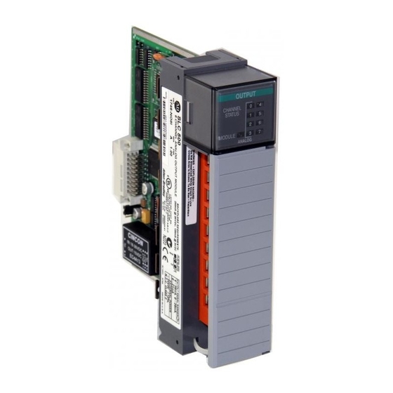
SLC 500 8-Point Analog Output Module Hardware Features The module contains a removable terminal block, providing connection for 8 analog output channels, which are specifically designed to interface with analog current and voltage devices. The 1746-NO8I provides eight channels of current outputs, while the 1746-NO8V provides eight channels of voltage outputs. -
Page 6: Determining Power Requirements
SLC 500 8-Point Analog Output Module Determining Power Requirements The module receives its power through the SLC 500 chassis backplane from the +5V dc/+24V dc chassis power supply. The +5V dc backplane supply powers the SLC circuitry, and the +24V dc backplane supply powers the module analog circuitry. - Page 7 SLC 500 8-Point Analog Output Module • With the jumper in the 1-2 shorted position, the module draws all of its power from the backplane of the SLC system. • With the jumper in the 2-3 shorted position, the module draws its 24V dc power from the external power supply;...
-
Page 8: Installation
SLC 500 8-Point Analog Output Module Installation Install the SLC 500 system in a properly rated (i.e., NEMA) enclosure. Make sure that the SLC 500 system is properly grounded. Choosing a Slot in the Chassis Two factors determine where the analog module should be located in the chassis: ambient temperature and electrical noise. - Page 9 SLC 500 8-Point Analog Output Module Remove Power Remove power before removing or installing this module. ATTENTION When you remove or install a module with power applied, an electrical arc may occur. An electrical arc can cause personal injury or property damage by: •...
- Page 10 SLC 500 8-Point Analog Output Module Module Installation and Removal The module fits into any slot, except the processor slot (0), in either an SLC 500 modular system or an SLC 500 fixed system expansion chassis (1746-A2). 1. Align the circuit board of the analog module with the card guide of the chassis as shown below.
-
Page 11: Wiring
SLC 500 8-Point Analog Output Module Wiring Preliminary Considerations Use the following guidelines in planning the system wiring for the analog modules: Before wiring any analog module, disconnect power from the ATTENTION SLC 500 system and from any other source to the analog module. - Page 12 SLC 500 8-Point Analog Output Module Wiring Procedure To wire your module, follow these steps: 1. Determine the length of cable you need to connect a channel to its field device. Remember to include additional cable to route the shield wire and foil shield to their ground points.
- Page 13 SLC 500 8-Point Analog Output Module Terminal Block The 1746-NO8 module contains an 18-position, removable terminal block. The terminal pin-out is shown below. Disconnect power to the SLC before attempting to install, ATTENTION remove, or wire the removable terminal block. To avoid cracking the removable terminal block, alternate the removal of the slotted terminal block release screws.
-
Page 14: Configuration
SLC 500 8-Point Analog Output Module Configuration The module operates in Class 1 or Class 3 mode. This section describes how to configure the module for Class 1 operation. Class 1 provides basic data output with no user scaling. No configuration is required. This mode is compatible with the 1746-NO4 module. - Page 15 SLC 500 8-Point Analog Output Module Table 6 1746-NO8 Data Format Definitions for 1746-NO4 Data Format Selected Data Value (counts) Corresponding Signal Output Range Min. Max. Min. Max. ±10V dc -32768 +32764 -10V dc +10V dc 0 to 10V dc +32764 0V dc +10V dc...
-
Page 16: Specifications
SLC 500 8-Point Analog Output Module Specifications Table 7 General Specifications Specification 1746-NO8I 1746-NO8V I/O Chassis Any 1746 chassis slot except slot 0 Location Backplane Current 120 mA at 5V dc 120 mA at 5V dc Consumption (maximum) 250 mA at 24V dc (J4 jumper set to RACK) 160 mA at 24V dc (J4 jumper set to RACK) 0 mA at 24V dc (J4 jumper set to EXT) 0 mA at 24V dc (J4 jumper set to EXT) - Page 17 SLC 500 8-Point Analog Output Module Table 8 Analog Output Specifications Specification 1746-NO8I 1746-NO8V Number of Outputs Output Type Current Voltage Output Range 0 to 21.5 mA ±10.25V dc Output Coding (proportional 0 to 32,767 -32,768 to +32,767 scaling) Output D/A Converter Resolution 16-bit 16-bit 366 nA/count...
- Page 18 SLC 500 8-Point Analog Output Module Table 9 Configuration and Status Specifications Specification 1746-NO8I 1746-NO8V Module ID Code Class 1: 3527 Class 1: 3528 Class 3: 12727 Class 3: 12728 Number of Output Channels • 4 to 20 mA Current Output Ranges •...
- Page 19 Hazardous Locations Groups A, B, C, D • CE marked for all applicable directives • C-Tick marked for all applicable acts SLC 500 is a trademark of Rockwell Automation. Belden is a trademark of Belden Inc. Publication 1746-IN026A-EN-P - July 2003...
-
Page 20: Rockwell Automation Support
Outside United States Please contact your local Rockwell Automation representative for return procedure. Publication 1746-IN026A-EN-P - July 2003 PN 40071-158-01(1) Copyright © 2003 Rockwell Automation, Inc. All rights reserved. Printed in the U.S.A.
Need help?
Do you have a question about the Allen-Bradley SLC 500 and is the answer not in the manual?
Questions and answers