Table of Contents
Advertisement
Quick Links
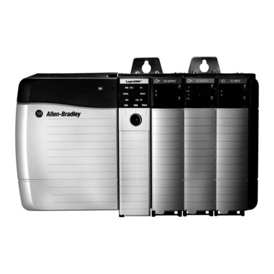
ControlLogix DH-485 Communications Module
Catalog Number(s) 1756-DH485
Inside . . .
For
About this Publication
Use this document to install the ControlLogix DH-485 communications
module.
Installation Instructions
Publication
1756-IN587A-EN-P - September 2005
See Page
8
8
9
10
11
12
14
15
16
17
18
19
Advertisement
Table of Contents

Subscribe to Our Youtube Channel
Related Manuals for Rockwell Automation Allen-Bradley ControlLogix DH-485


Summary of Contents for Rockwell Automation Allen-Bradley ControlLogix DH-485
-
Page 1: Table Of Contents
Installation Instructions ControlLogix DH-485 Communications Module Catalog Number(s) 1756-DH485 Inside . . . See Page Identify Module Features Prepare the Chassis for Module Installation Determine Module Slot Location Install or Remove the Module While Power Is Applied Install the Module Connect the Module Channels to the DH-485 Network Apply Chassis Power Check Power Supply and Module Status... -
Page 2: Important User Information
In no event will Rockwell Automation, Inc. be responsible or liable for indirect or consequential damages resulting from the use or application of this equipment. -
Page 3: Environment And Enclosure
ControlLogix DH-485 Communications Module 3 Environment and Enclosure This equipment is intended for use in a Pollution Degree 2 ATTENTION industrial environment, in overvoltage Category II applications (as defined in IEC publication 60664-1), at altitudes up to 2000 meters without derating. This equipment is considered Group 1, Class A industrial equipment according to IEC/CISPR Publication 11. -
Page 4: Prevent Electrostatic Discharge
4 ControlLogix DH-485 Communications Module Prevent Electrostatic Discharge This equipment is sensitive to electrostatic discharge, which can ATTENTION cause internal damage and affect normal operation. Follow these guidelines when you handle this equipment: • Touch a grounded object to discharge potential static. •... - Page 5 ControlLogix DH-485 Communications Module 5 Single-point Serial Communication Connections If you connect or disconnect the serial cable with power applied WARNING to this module or the serial device on the other end of the cable, an electrical arc can occur. This could cause an explosion in hazardous location installations.
-
Page 6: North American Hazardous Location Approval
6 ControlLogix DH-485 Communications Module North American Hazardous Location Approval The following information applies Informations sur l'utilisation de cet when operating this equipment in équipement en environnements hazardous locations: dangereux: Products marked “CL I, DIV 2, GP A, B, C, Les produits marqués “CL I, DIV 2, GP A, B, C, D”... - Page 7 ControlLogix DH-485 Communications Module 7 The following information applies Informations sur l'utilisation de cet when operating this equipment in équipement en environnements hazardous locations: dangereux: EXPLOSION HAZARD RISQUE D'EXPLOSION WARNING WARNING Do not disconnect Couper le courant ou equipment unless power s'assurer que has been removed or the l'environnement est classé...
-
Page 8: Identify Module Features
8 ControlLogix DH-485 Communications Module Identify Module Features Use this figure to identify module hardware components. Module Features Backplane Alphanumeric Wiring Connector Status Indicator Label Channel Module Status Indicators Channel A Connector Channel B Connector 43842 Prepare the Chassis for Module Installation Before you install the 1756-DH485 module, you must install and connect a ControlLogix chassis and power supply. -
Page 9: Power Supply
ControlLogix DH-485 Communications Module 9 For information on installing these products, refer to the publications listed in the table Power Supply. Power Supply Chassis Type Chassis Power Supply Power Supply Series B: 1756-A4, -A7, -A10, 1756-IN080 1756-PA72 1756-IN078 -A13, -A17 1756-PB72 1756-PA75 1756-IN596... -
Page 10: Install Or Remove The Module While Power Is Applied
10 ControlLogix DH-485 Communications Module Install or Remove the Module While Power Is Applied You can install or remove the module while chassis power is applied if you observe the following precautions. When you insert or remove the module while backplane power WARNING is on, an electrical arc can occur. -
Page 11: Install The Module
ControlLogix DH-485 Communications Module 11 Install the Module Do not force the module into the backplane connector. If you ATTENTION cannot seat the module with firm pressure, check the alignment. Forcing the module into the chassis can damage the backplane connector or the module. Align the circuit board with top and bottom guides in the chassis. -
Page 12: Remove Or Replace The Module (When Applicable)
12 ControlLogix DH-485 Communications Module Remove or Replace the Module (When Applicable) Push on upper and lower module tabs to disengage them. Slide the module out of the chassis. 43237 If you are replacing an existing module with an identical one, and you want to resume identical system operation, you must install the new module in the same slot. - Page 13 ControlLogix DH-485 Communications Module 13 Connect the 1756-DH485 Module to the 1761-NET-AIC Converter 1. Use the 1756-CP3 cable to connect each channel to a 1761-NET-AIC advanced interface convertor. 2. Connect the right-angle connector end of the cable to the 1761-NET-AIC converter. Right-angle connector end of 1756-CP3 cable 1 - DCD...
-
Page 14: Apply Chassis Power
14 ControlLogix DH-485 Communications Module Connect the 1761-NET-AIC Converter to the DH-485 Network Use the RS-485 connector to connect the 1761-NET-AIC converter to the DH-485 network. For more information on how to use the 1761-NET-AIC convertor, see the following publications: •... -
Page 15: Check Power Supply And Module Status
ControlLogix DH-485 Communications Module 15 Check Power Supply and Module Status Alphanumeric status indicator illuminates and cycles through a sequence of messages (described in the Alphanumeric Display Descriptions table). Module OK status indicator is solid red, Power Supply indicator then flashing green. is green. -
Page 16: Troubleshoot The Power Supply
16 ControlLogix DH-485 Communications Module Troubleshoot the Power Supply If the alphanumeric indicator on the 1756-DH485 module does not cycle through these messages when you turn the power on, refer to the Power Supply Status table and to the Troubleshooting section that follows. Power Supply Status POWER Indicator Power Supply Status... -
Page 17: Interpret The Led Status Indicators
ControlLogix DH-485 Communications Module 17 Alphanumeric Display Descriptions Code Description Recommended Action Normal operation for that None. channel. LINK None Interpret the LED Status Indicators The LED status indicators on the module provide information about your module and the status of each channel. The following tables outline the indicator condition and the corresponding status, and explain what each condition means. -
Page 18: Set The Network Parameters And Configure The Module
18 ControlLogix DH-485 Communications Module LED Actions Channel A or B Channel Status Recommended Action Indicator Not online. Place channel online. Solid Green Operating. None, normal operation. Flashing Green No other node on the Check cables. network. Solid Red Hardware fault. Reboot module. -
Page 19: Specifications
ControlLogix DH-485 Communications Module 19 Specifications 1756-DH485 ControlLogix DH-485 Communications Module - Specifications Specification Value Module Location ControlLogix chassis Maximum Backplane 850 mA @ +5.1V dc and 1.7mA @ 24V dc Current Load from I/O chassis backplane Power Dissipation, Max 4.5 W Thermal Dissipation, Max 15.4 BTU/hr... -
Page 20: Environmental Specifications
20 ControlLogix DH-485 Communications Module Environmental Specifications Specification Value Operational IEC 60068-2-1 (Test Ad, Operating Cold), Temperature IEC 60068-2-2 (Test Bd, Operating Dry Heat), IEC 60068-2-14 (Test Nb, Operating Thermal Shock): 0...60 °C (32...140 °F) Storage IEC 60068-2-1 (Test Ab, Un-packaged Non-operating Cold), Temperature IEC 60068-2-2 (Test Bb, Un-packaged Non-operating Dry Heat),... - Page 21 ControlLogix DH-485 Communications Module 21 Environmental Specifications Specification Value Surge Transient IEC 61000-4-5: Immunity +/-1 kV line-earth (CM) on communications ports Conducted RF IEC 61000-4-6: Immunity 10 Vrms with 1 kHz sine-wave 80%AM from 150 kHz...80 Magnetic Field IEC 61000-4-8: Immunity 30 A/m at 50 Hz Enclosure Type...
-
Page 22: Additional Resources
• Contact your distributor or Rockwell Automation representative • Call 800.963.9548 (USA/Canada) or 001.320.725.1574 (outside USA/Canada) ControlLogix, DH+, DH-485, RSLogix 5000, and RSLinx are trademarks of Rockwell Automation, Inc. Trademarks not belonging to Rockwell Automation are property of their respective companies. Publication... - Page 23 ControlLogix DH-485 Communications Module 23 Notes: Publication 1756-IN587A-EN-P - September 2005...
-
Page 24: Rockwell Automation Support
Rockwell Automation Support Rockwell Automation provides technical information on the web to assist you in using its products. At http://support.rockwellautomation.com, you can find technical manuals, a knowledge base of FAQs, technical and application notes, sample code and links to software service packs, and a MySupport feature that you can customize to make the best use of these tools.
Need help?
Do you have a question about the Allen-Bradley ControlLogix DH-485 and is the answer not in the manual?
Questions and answers