Table of Contents
Advertisement
Quick Links
Hub Service Technical Manual
704 Series 2
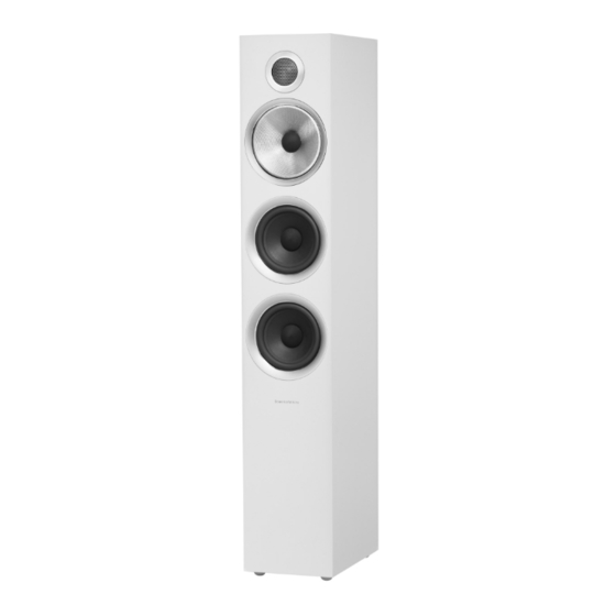
Gloss Black
Satin White
Rosenut
The contents of this document and associated files contain confidential information that is propriety to B&W
Group Ltd., and are intended solely for the purpose of servicing the product. The information is intended for use
by service technicians familiar with electronic products. No part of the contents should be supplied or published
elsewhere.
Page 1
© B&W Group Ltd 2017
Advertisement
Table of Contents

Related Manuals for Bowers & Wilkins 704 S2 Series


Summary of Contents for Bowers & Wilkins 704 S2 Series
- Page 1 Hub Service Technical Manual 704 Series 2 Gloss Black Satin White Rosenut The contents of this document and associated files contain confidential information that is propriety to B&W Group Ltd., and are intended solely for the purpose of servicing the product. The information is intended for use by service technicians familiar with electronic products.
-
Page 2: Table Of Contents
Revision History Date Revision Details 21/05/2018 Creation Contents Front Cover Page 1 Revision History Page 2 Contents Page 2 Introduction Page 3 Technical Sheet Page 4 Exploded Diagram & Parts List Page 5 - 6 HF/ MF Crossover Diagram & Parts List Page 7 LF Crossover Diagram &... - Page 3 Introduction Please read this manual carefully before commencing servicing! Only qualified and authorised technicians should attempt to service this product. Antistatic Precautions (ESD) Electronic devices and components are extremely sensitive to electrostatics (ESD). Always observe ESD precautions when handling electronic modules or PCBs.
- Page 4 704 S2 Series Technical Sheet Technical features Decoupled Carbon Dome tweeter Continuum cone FST midrange Decoupled midrange Aerofoil profile bass cones Flowport™ Description 3-way vented-box system Drive units 1x ø25mm (1 in) Decoupled Carbon Dome high- frequency 1x ø130mm (5 in) Continuum cone FST midrange 2x ø130mm (5 in) Aerofoil profile bass...
-
Page 5: Exploded Diagram & Parts List
Exploded Diagram & Parts List The contents of this document and associated files contain confidential information that is propriety to B&W Group Ltd., and are intended solely for the purpose of servicing the product. The information is intended for use by service technicians familiar with electronic products. - Page 6 Parts List PART # PART # BLACK WHITE ITEM PART NAME DESCRIPTION GG12742 GG12742 NXM10000056703000 Gasket 5” Chassis PM/CM/68x S2 HH35904 HH35904 NXM10000067381000 Scr M4x12 Cap Hd CR3 Black LF26824 LF26824 NXM10000099337000 Bass Unit 5” 704 S2 PP17601 PP17601 NXM10000056095000 Port Tube Inc Flare 50x25mm Abs Black RR35211 RR35289...
-
Page 7: Hf/ Mf Crossover Diagram & Parts List
HF/ MF Crossover Diagram & Parts List ITEM DRAWING NUMBER DESCRIPTION PART # NXD10000108616 ASSY X-Over CM8 HF/ MF S3 XX16969 NXD10000110813 PCB 3 Way—HF/ MF S3 CC72133 NXD10000065997 CM8 S2 HF/ MF Harness Assembly ZX10146 Cap5.6 M-Cap 450VDC EVO Silver Gold Oil CC64653 Cap 47uF PP 250V Carli CC58164... -
Page 8: Lf Crossover Diagram & Parts List
LF Crossover Diagram & Parts List ITEM DRAWING NUMBER DESCRIPTION PART # NXD10000108617 ASSY X-Over CM8 LF S3 XX16950 NXD10000108566 PCB 3 Way—LF—CMS3 CC72125 NXD10000066262 CM8 S2 LF Harness Assembly ZX10197 Cap 120uF 100V 5% Elec B04 CC57642 Cap 0.01uF TDK 630V RAD EPCOS 10mm Pitch CC87165 Ind 2.52mH 1.2mm P2535+P4507 x 2 Cose Pacific ZL11231... -
Page 9: Tool Kit
1. Tool Kit The tools listed in the below table are required to carry out the servicing of the 704 Series 2 Speakers. HF/ MF Tool Kit 2017 Phillips Screwdriver Allen Key 3.0mm The contents of this document and associated files contain confidential information that is propriety to B&W Group Ltd., and are intended solely for the purpose of servicing the product. -
Page 10: Cosmetic Inspection
2. Cosmetic Inspection A Cosmetic Inspection is done visually and should be done before any work commences. This is to ensure that there is no external damage to the 704 Series 2 Speaker. The Cabinet (Including Speaker Terminals & Flowport) (1), Tweeter (2), Mid Driver (3), Bass Driver (4) should be checked for damage during the inspection. -
Page 11: Plinth Removal
3. Plinth Removal Prior to servicing the 704 Series 2, it is recommended that the Plinth is removed. To safely remove the Plinth without damaging the 704 Series 2 we recommend following the below steps: Place the cloth bag over the top of the 704 Series 2 ensuring that the Tweeter and top of the cabinet are covered. -
Page 12: Tweeter Removal
4. Tweeter Removal Start by using Tool 1.5 - MM09989 HF Trim Removal Tool. Insert the Lip of the Trim Removal Tool into the Tweeter Trim. Lever the Trim Removal Tool against the Grille until Tweeter Trim begins to lift from the cabinet (1). Note: Take care when putting pressure on the Grille so not to damage the Tweeter The Outer-Rim can now be removed and placed to one side awaiting reassembly. - Page 13 Carefully ease the Tweeter forward from the cabinet and remove the Black (-) (1) and Red (+) (2) Leads. Ensure that the Foam Gasket (3) remains in position for reassembly. (Take note of the red paint on the right (+) Tweeter connection, this is to show the Red (+) cable position) Note: If the Tweeter is stuck in position and cannot be eased forward it may be necessary to remove the Mid/Base Speaker.
- Page 14 With the Plastic Retainer (1) removed you are able to use the magnetic side of Tool 1.5 – MM09989 HF Trim Removal Tool to gently lift the Tweeter Grille (2) from the Tweeter Assembly (3) IMPORTANT: Ensure you do not touch the Tweeter when removing the Grille as this will mark or damage the Tweeter.
-
Page 15: Mid Removal
5. Mid Removal Start by gently easing out the Foam Dust Cap (1) at the centre of the Mid Unit. Minimal force is required as the Dust Cap should simply slot in and out of place. Once the Dust Cap is removed you will see the Drawbar Assembly (2). For adjustment of the Drawbar please refer to 5. - Page 16 Once the MF Removal Tool has been correctly assembled you can use it to unscrew the nut from the Drawbar (1). Note: With the nut removed the Mid Unit is now sat freely on the Drawbar. Ensure that the Mid Unit does not slide forward as this may damage the cabinet. Now that the nut is removed the next step is to adjust the MF Removal Tool to allow for its second function.
- Page 17 You can now screw the adjusted MF Removal Tool into the center of the M id Unit (1). Once the tool has been tightened in position you will be able to ease the Mid Unit off the drawbar and out of the cabinet (2). Note: Take note of the cable positions •...
-
Page 18: Drawbar Adjustment
Reassembling the Mid Please work backwards through the Mid Removal process ensuring all the below points. • Brown (+) and Blue (-) cables are fitted securely and correctly • Mid Unit is positioned on the Drawbar with the bar going through the hole in the back. •... - Page 19 To carry out the adjustments you should attach Tool 1.3 – HH15121 MF Removal Tool to the nut (1) and then slide Tool 1.1 – HH15148 Screwdriver 4mm x 100mm into the end of the MF Removal Tool. Position the Screwdriver so that it finds the slot in the top of the Drawbar (2).
-
Page 20: Bass Removal
7. Bass Removal Start by putting your fingers against the Rubber inner and your thumb on the edge of the Cabinet and gently ease the Aluminium Trim (1) outwards. Pull evenly around the Aluminium Trim so as not to bend the Plastic Pegs. Con- tinue this until the Trim comes away from the Cabinet. - Page 21 Disconnect the Green (-) and Yellow (+) Cable connectors to fully remove the Bass Unit. En- sure not to damage the Gasket when removing the Bass Unit. Note: The Green (-) and Yellow (+) Cables have different sized connectors to ensure correct positions when reassembling.
-
Page 22: Terminal Tray/ Port Removal
8. Terminal Tray/ Port Removal The Terminal Tray/ Port (1) can be found at the rear of the 704 Series 2. To remove the Terminal Tray/ Port you need to carefully unscrew 6 x screws (1-6) With the Terminal Tray/ Port detached you can gain access to the Speaker Terminal Connectors. - Page 23 Correct position of the cables can be determined using the below image and bullet points: • Red (HF+) (1) • Black (HF-) (2) • Blue (LF-) (3) • Brown (LF+) (4) Reassembling the Terminal Tray/ Port Please work backwards through the Terminal Tray/ Port Removal process ensuring all the below points.
-
Page 24: Hf/ Mf & Lf Crossovers
9. HF/ MF & LF Crossovers The 704 Series 2 has two Crossovers HF/ MF Crossover and LF Crossover. We recommend that the removal process is carried out while the 704 Series 2 is laying on its back to ensure cabinet safety. - Page 25 LF Crossover Removal With the Bass Units and Terminal Tray/ Port removed you have clear access to the Crossovers. To remove the LF Crossover you need to begin by unscrewing 4 x screws (1-4). With the screws removed the Crossover is now detached from the cabinet.
- Page 26 HF/MF Crossover Removal With the Bass Units and Terminal Tray/ Port removed you have clear access to the Crossovers. To remove the HF / MF Crossover you also need to remove the Mid Unit and Tweeter. To remove the Mid unit please follow the 4. Mid Removal process which begins on Page 15. To remove the Tweeter please follow the 4.
- Page 27 All cables should now be free. To remove the HF/ MF Crossover from the cabinet you need to unscrew 4 x screws (1-4). With the 4 x screws removed you can fully remove the HF/ MF Crossover. Reassembling the HF/ MF Crossover Please work backwards through the HF/ MF Crossover Removal process ensuring all the below points.
-
Page 28: Functional Test
10. Functional Test (Stethoscope Examination of Speakers) Aim of the Test The stethoscope functional test can quickly reveal any air leaks or flaws following a repair to a loudspeaker. The only sound coming from a loudspeaker enclosure should be from the driver components themselves, not the surfaces or seams of the speaker cabinet. - Page 29 Pan between the Tweeter and Mid/Bass, by moving the listening piece between points 1 and 2. Sensitive panning between drivers allows you to listen for phase effects such as a notch in the frequency response at crossover. Carefully move the listening tube about the surface of the enclosure noting the sound level remains consistent.
-
Page 30: Cleaning
11. Cleaning The cabinet surfaces will usually only require dusting however if you wish to use an aerosol or other cleaning product, apply the cleaner onto a clean soft cloth (not directly onto the product) and test a small area first as some cleaning products could damage the surface of the cabinet. Avoid products that are abrasive, contain acid, alkali or antibacterial agents. -
Page 31: Spare Parts
12. Spare Parts List TYPE PART # DESCRIPTION ACCESSORIES Foam Bung 2 Part (55OD- 32ID/OD)x45-50mm FF24295 ACCESSORIES Gasket 5" Chassis PM/CM/68x s2 GG12742 ACCESSORIES CM S2 HF GASKET GG14184 ACCESSORIES HH05010 Allen Key 5mm A/F ACCESSORIES MF Centraliser Nut HH36463 ACCESSORIES Decoupler MF - front CMs3 5in MM14613... -
Page 32: Product Test List
13. Product Test List Passive Loudspeakers • Sweep Frequency Test 20 Hz – 20 kHz (3 volts, all products) check for distortion & balance between left & right speaker • Spot Frequency Test 4 volts – Book shelf 5 volts – Floor standing 6 volts –... -
Page 33: Test Result Sheet
14. Test Result Sheet Reason for return: □ In Warranty □ Out of Warranty □ Chargeable PAT Testing Required Date done: Received packaging re-useable - - Yes / No Serial no. 1. Tools and Equipment Required Part Number Description HF/ MF Tool Kit 2017 Phillips Screwdriver Allen Key 3.0mm Spanner 17mm... - Page 34 3. Functional Test: Add initials to the box Connect 707 S2 Speakers to Amp/CD Player and check for Sound Yes/No Check audio for Tweeter & Mid/bass output is working Yes/No 5. Speaker Bi-Wiring Check RH/LH speakers are working Bi-wire Yes/No 8.
Need help?
Do you have a question about the 704 S2 Series and is the answer not in the manual?
Questions and answers