Table of Contents
Advertisement
Advertisement
Table of Contents

Related Manuals for Generac Power Systems Power Zone Pro Sync


Summary of Contents for Generac Power Systems Power Zone Pro Sync
- Page 1 ® Owner’s Manual ® Power Zone Pro Sync SAVE THIS MANUAL FOR FUTURE REFERENCE...
- Page 2 WARNING CANCER AND REPRODUCTIVE HARM www.P65Warnings.ca.gov. (000393a) Owner’s Manual for Power Zone Pro Sync...
-
Page 3: Table Of Contents
Setup for Backup Mode in MPS ........23 Codes and Standards ..........6 Install/Replace Devices ..........24 Protections ..............6 Replace the Power Zone Pro Sync Main Controller in an MPS ..............24 Control Panel and Touch Screen ........6 Replace the Power Zone Pro Sync Display ....25 Specifications ...............7... - Page 4 This page intentionally left blank. Owner’s Manual for Power Zone Pro Sync...
-
Page 5: Section 1 Introduction And Safety
This equipment generates, uses, and can radiate radio frequency energy and, if not Thank you for purchasing a Generac Power Systems, installed and used in accordance with the instruction Inc. product. This system has been designed to provide... -
Page 6: Safety Rules
Electrocution. Water contact with a power manual and thoroughly understand all instructions before source, if not avoided, will result in death using this equipment. or serious injury. (000104) Owner’s Manual for Power Zone Pro Sync... -
Page 7: Battery Hazards
(000162) WARNING Explosion. Batteries emit explosive gases while charging. Keep fire and spark away. Wear protective gear when working with batteries. Failure to do so could result in death or serious injury. (000137a) Owner’s Manual for Power Zone Pro Sync... - Page 8 Introduction and Safety This page intentionally left blank. Owner’s Manual for Power Zone Pro Sync...
-
Page 9: Section 2 General Information
The Generac Power Zone Pro Sync is a system of • Customer Programmable Built-in Multichannel PLC controllers that communicate with one another to power Logic Controller and control all facets of a Generac Power Zone Pro Sync • Support of Third-party Controlled Paralleling Generator. -
Page 10: Voltage Regulation (Single Or Three-Phase Module Options)
Control Panel and Touch Screen • 1 RS-485 Port • Auto/Manual/Off • 2 Switchable 12 V Power Outputs • Alarm Acknowledge Button NOTE: Actual I/O may vary due to configuration. • Audible Alarm • Emergency Stop Owner’s Manual for Power Zone Pro Sync... -
Page 11: Specifications
Control Connections AC Power Fail Relay, Form C, 2 A, 12/24 V NOTE: Normally Open (N.O.) Contact closes when AC line voltage is applied. N.O. Contact opens when AC line voltage is removed. Owner’s Manual for Power Zone Pro Sync... - Page 12 See Owner’s Manual for the individual module NOTE: The communications cables should not be run in the same conduit or in the same wire grouping as any high voltage or high current conductors. Owner’s Manual for Power Zone Pro Sync...
-
Page 13: System Components
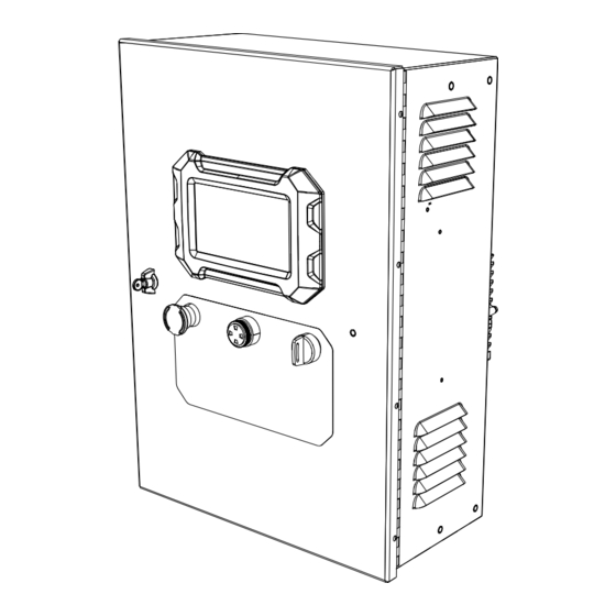
Battery Charger (if equipped) Battery DC Connection AVR Driver (if equipped) Battery Charger AC Connector Deutsch Engine Interface Connector Current Transducer (CT) Connection Starter Contactor Circuit Breaker Control and Alternator Control Cabinet Connections Main Controller Owner’s Manual for Power Zone Pro Sync... -
Page 14: Dimensions
12.09 in (30.7 cm) 10.91 in (27.7 cm) 10.20 in (25.9 cm) 16.14 in (41.0 cm) 24.65 in (62.6 cm) NOTE: Dimensions shown are for reference only, and may vary depending on generator size and application. Owner’s Manual for Power Zone Pro Sync... -
Page 15: Power Zone Pro Sync System Block Diagram
General Information Power Zone Pro Sync System Block Diagram The Power Zone Pro Sync System and all of its components are visually represented in Figure 2-3. This configuration layout is typical for most generator systems, but will not be an exact match for every setup. -
Page 16: Main Controller
The Power Zone Pro Sync Main Controller (Assembly excitation voltage after reaching nominal frequency. No. 10000004337) is the central operating controller for the Power Zone Pro Sync system. All external modules Three-Phase Automatic Voltage are connected to it and communicate with it using CAN Regulator Driver (If Equipped) bus (Controller Area Network), Ethernet, or RS-485. -
Page 17: Fuses
The Battery Charger can charge either a 12 V or 24 battery, in 10A or 20A mode. The charging modes need to be selected using the Power Zone Pro Sync Display for proper operation. The Main Controller initializes the Battery Charger over CAN bus. The Battery Charger provides the Main Controller with the status of the generator battery. -
Page 18: Analog Battery Charger (If Equipped)
Power Zone Pro Sync G0071500 Permissive/Loadshed, NEMA 3R The Power Zone Pro Sync Permissive and Loadshed Panel (P&L) controls the permissive signals and loadshed signals sent to the ATSs (Automatic Transfer Switches) in an MPS. The P&L monitors the generators in the MPS to determine which are connected to the Owner’s Manual for Power Zone Pro Sync... -
Page 19: Customer Connections
19) is connected to control signal A-5, and DOUT #20 • Relay Boards (Pin BS3-20) is connected to control signal A-6. These • Run Relays (If Equipped) outputs can be configured via the Power Zone Pro Sync • Utility Connection Display provide desired... - Page 20 Figure 2-5. Relay Board Schematic Figure 2-6. Customer Relay Board IMPORTANT NOTE: Know the power rating for the relay to avoid damage to the generator system. 009368 Figure 2-7. Customer Relay Board Schematic Owner’s Manual for Power Zone Pro Sync...
-
Page 21: Run Relays (If Equipped)
General Information Run Relays (If Equipped) Table 2-1. Connector Torque and The Power Zone Pro Sync System can have an optional Acceptable Wire Range Run Relay installed. This is a two pole relay with two separate commons, COM1 and COM2. There is a set of... -
Page 22: Remote Start
Figure 2-10. 2-wire Remote Start Remote Start Device N.O. Remote Start Input 1 Common Connection Generator/Engine Control Logic 011019 Figure 2-9. 3-wire Remote Start Table 2-2. Power Zone Pro Sync Remote Remote Start Device Start Connections N.O. Terminal Main Input Wire N.C. -
Page 23: Rap (Remote Annunciator Panel) And Rrp (Remote Relay Panel) (If Equipped)
RAP. Specifying which RAPs are System RAPs is done during initial configuration through the Power Zone Pro Sync Display. RAPs can optionally be connected to the RS-485 port for an individual generator, but not as a System RAP. - Page 24 General Information 009369 Figure 2-11. 3 MPS Generator System Interconnect Diagram (Typical) Owner’s Manual for Power Zone Pro Sync...
- Page 25 Main Controllers, they must be connected to ports 2 or 3, either directly or through a non-powered Ethernet switch. When there are no more Main Controllers remaining to connect, any other module may connect to ports 2, 3, or 4. Owner’s Manual for Power Zone Pro Sync...
- Page 26 General Information This page intentionally left blank. Owner’s Manual for Power Zone Pro Sync...
-
Page 27: Section 3 Operation
Main Controller is connected to the next via Ethernet port 2 or 3. Each generator in a Power Zone Pro Sync system will likely have its own RAP(s), most commonly located in a control room inside the building. In addition to the individual RAP(s) for each generator, one or more RAPs, known as System RAPs, will likely be in the system. -
Page 28: Install/Replace Devices
Figure 3-4. Select “Setup” (B). tions. Select “Communications”. Select “Device Manager”. Replace the Power Zone Pro Sync Main Figure 3-5. From the list of devices, select the Controller in an MPS unit being replaced. Verify the “Out of Service” selection (C) is set to “False”. -
Page 29: Replace The Power Zone Pro Sync Display
Run the unit to recalibrate voltage and current. Select the “Clear cached data” button to ensure the new Display is reset to factory defaults. Replace the Power Zone Pro Sync Display Upgrade Display firmware to the latest version from GenService:... -
Page 30: Replace The Power Zone P&L Controller
Ethernet cables. 010923 Replace the circuit board but ONLY plug in the Ethernet cable for the Display. Figure 3-9. Select Annunciator Owner’s Manual for Power Zone Pro Sync... - Page 31 READY” LED should be flashing green. Temporarily take the generator out of AUTO mode (only if it is safe to do so). Verify the horn sounds and the “NOT IN AUTO” LED is lit. Owner’s Manual for Power Zone Pro Sync...
- Page 32 Operation This page intentionally left blank. Owner’s Manual for Power Zone Pro Sync...
-
Page 33: Section 4 Troubleshooting
Non-Latching Warning Not Available Main Circuit Breaker Diagnostic Trouble Code NOTE: Not all definitions are reflected in the table above. Power Zone Pro Sync Main Controller Internal Alarms Alarm Display Text Type Alarm Description UNKNOWN IA Internal Alarm is invalid or unrecognzied... - Page 34 ENGINE STALLED Engine stopped running unexpectedly - Generator shuts down and restarts STARTER NOT ENGAGED Cranking voltage profile indicates starter did not engage BOSCH THROTTLE STUCK Bosch actuator position does not reflect commanded position Owner’s Manual for Power Zone Pro Sync...
- Page 35 CAN BAT1 MISSING MODULE Power Zone CAN bus Battery Charger configured, but not responding. Can be numbered 1-4. CAN UNKNOWN MISSING MODULE An unknown Power Zone CAN bus module configured, but not responding. Owner’s Manual for Power Zone Pro Sync...
- Page 36 AI, AO, DI and DO XXX NOT SETUP Alarms. REMOTE START 1 NOT SETUP AI, AO, DI and DO XXX NOT SETUP Alarms. MCB STATUS 1 NOT SETUP AI, AO, DI and DO XXX NOT SETUP Alarms. Owner’s Manual for Power Zone Pro Sync...
- Page 37 AI, AO, DI and DO XXX NOT SETUP Alarms. COOLANT LEVEL 1 NOT SETUP AI, AO, DI and DO XXX NOT SETUP Alarms. GEN REAL PWR WATTS LL TOTAL NOT SETUP AI, AO, DI and DO XXX NOT SETUP Alarms. Owner’s Manual for Power Zone Pro Sync...
- Page 38 AI, AO, DI and DO XXX NOT SETUP Alarms. GEN VOLTAGE AB NOT SETUP AI, AO, DI and DO XXX NOT SETUP Alarms. GEN VOLTAGE BC NOT SETUP AI, AO, DI and DO XXX NOT SETUP Alarms. Owner’s Manual for Power Zone Pro Sync...
- Page 39 Excitation Control Output #2 has been configured by the user as something else INVALID DI CONFIGURATION FOR SHUTDOWN Warning condition has occurred as Activate BYPASS Shutdown Bypass digital input is not configured or configured incorrectly Owner’s Manual for Power Zone Pro Sync...
- Page 40 If the number of indicates switch position attempts is exceeded correctly. Clear the before the transfer switch alarm using the Display. successfully closes, a fault occurs. Owner’s Manual for Power Zone Pro Sync...
- Page 41 Verify proper fuel, attempts. exceeded. throttle is opening, ignition is firing, starter is engaging, and RPM is reading. Clear the alarm using the Display. Owner’s Manual for Power Zone Pro Sync...
- Page 42 TASK EXIT A Main Controller operating A Main Controller operating Power cycle the Main system task exited unexpectedly. system task was incorrectly Controller and clear the terminated. alarm using the Display. Owner’s Manual for Power Zone Pro Sync...
- Page 43 SERVICE of service". It needs to be as “out of service”. when this generator is WARNING returned to service to participate returned to service and as part of the MPS. marked as such. Owner’s Manual for Power Zone Pro Sync...
- Page 44 Clear the alarm away from the target jammed, the throttle motor and not moving quickly using the Display. enough toward the becoming weak, the actuator target. driver module failing, or the throttle sensor failing. Owner’s Manual for Power Zone Pro Sync...
- Page 45 It then shuts down conditions that set this. alarm. Clear the alarm the engine. using the Display. Owner’s Manual for Power Zone Pro Sync...
- Page 46 ACTIVE ECU STOP shut down. This can result in a LIGHT” shutdown alarm will nuisance shutting down of the set. generator. Therefore, on Volvo powered generators, this warning indicates a pending shutdown condition. Owner’s Manual for Power Zone Pro Sync...
- Page 47 Display. operation of the Air/Fuel ratio control or nuisance emissions faults. Failure to correct the settings could result in damage to the engine or emissions control system. Owner’s Manual for Power Zone Pro Sync...
- Page 48 Main Controller. If after 600 Controller and the milliseconds the Main Governor. Clear the Controller has not received shutdown alarm using a message from the the Display. module, the shutdown alarm is activated. Owner’s Manual for Power Zone Pro Sync...
- Page 49 Main Controller shutdown alarm using to the error the module is over CAN bus. the Display. reporting. See the AVR manual for each error message and description. Owner’s Manual for Power Zone Pro Sync...
- Page 50 There may not be a way to tell Controller that has reported warning is resolved. which warning has been triggered a warning, but the address without knowing what module it of the module is unknown, came from. corrupted, or invalid. Owner’s Manual for Power Zone Pro Sync...
- Page 51 It unknown, corrupted, or may be harder to troubleshoot the invalid. cause of this warning since the address of the module is unknown. Owner’s Manual for Power Zone Pro Sync...
- Page 52 Shutdown Alarm memory improperly, the Main using the memory available using the Display. If the Controller might overwrite the for temporary use. fault persists, contact program memory. technical support. Owner’s Manual for Power Zone Pro Sync...
- Page 53 0.2V of its Main Controller. Clear than 0.5 seconds. There are +5V, nominal voltage. the shutdown alarm -5V, 3.3V, and 36V voltage using the Display. references in the Main Controller. Owner’s Manual for Power Zone Pro Sync...
- Page 54 CAN address is invalid. Clear the shutdown alarm using the Display. • The Governor type selected is invalid. • The Actuator type selected is invalid. Owner’s Manual for Power Zone Pro Sync...
- Page 55 OFF. Verify CAN bus MIC3+ Ignition Module. received from the MIC3 in communications the expected time frame. between the Main Controller and the MIC3. Clear the shutdown alarm using the Display. Owner’s Manual for Power Zone Pro Sync...
- Page 56 If it the sensor. is dual fuel, go to the Dual Fuel Setup screen on the Display and complete the setup for the dual fuel sensor. Owner’s Manual for Power Zone Pro Sync...
- Page 57 Clear the is checked that it is not shutdown alarm using used by the user as a PWM the Display. Signal. If it is configured as a PWM then this Shutdown Alarm is set. Owner’s Manual for Power Zone Pro Sync...
- Page 58 Shutdown Bypass” to input. An “Invalid DI clear the warning. This Configuration Shutdown warning can also be Bypass” Warning is set. cleared by disabling the Shutdown Bypass setting on the Engine Configuration screen. Owner’s Manual for Power Zone Pro Sync...
-
Page 59: Power Zone Pro Sync Digital Output Functions (Dof)
Troubleshooting Power Zone Pro Sync Digital Output Functions (DOF) DOF Description FC DOF USER CONFIG 01 - 40 User Configurable DOF (there are 40 total), usually used with a PLC Program FC DOF START RELAY Status of the Starter Contactor Relay... - Page 60 Generator has been marked as OUT OF SERVICE. FC DOF SERVICE NEEDED Service time for a maintenance item has expired. FC DOF LINE POWER Indicates one or more ATSs in the system are in the Utility position. Owner’s Manual for Power Zone Pro Sync...
- Page 61 Remote Annunciator LED BATTERY CHARGER FAILED ALARM indicator state. FC DOF RAP OVERSPEED SHUTDOWN Engine RPM is too high. FC DOF TRANSFER SWITCH ERROR ALARM At least one transfer switch has an alarm. Owner’s Manual for Power Zone Pro Sync...
- Page 62 FC DOF IF HW OVERSPEED SHUTOFF Status of Hardware Overspeed Circuit causing a shutdown of the generator. FC DOF IF SYSTEM RESET OCCURRED xx Main controller reset has occurred. “xx” can be number 1- Owner’s Manual for Power Zone Pro Sync...
- Page 63 Main Controller CAN bus message. “x” can be number 1-4. FC DOF IF RPM1 SENSOR FAIL RPM sensor fault is active. FC DOF AI OVER FREQ ALARM Frequency is too high on output voltage. Owner’s Manual for Power Zone Pro Sync...
-
Page 64: Ai Channel Dofs
FC DOF AI CHANNEL xx FAULT 2 FC DOF AI CHANNEL xx FAULT 3 FC DOF AI CHANNEL xx FAULT 4 FC DOF AI CHANNEL xx SENSOR FAULT FC DOF AI CHANNEL xx EVENT Owner’s Manual for Power Zone Pro Sync... - Page 65 Troubleshooting This page intentionally left blank. Owner’s Manual for Power Zone Pro Sync...
- Page 66 Troubleshooting This page intentionally left blank. Owner’s Manual for Power Zone Pro Sync...
- Page 68 ©2020 Generac Power Systems, Inc. S45 W29290 Hwy. 59 All rights reserved. Waukesha, WI 53189 Specifications are subject to change without notice. 1-888-GENERAC (1-888-436-3722) No reproduction allowed in any form without prior written www.generac.com consent from Generac Power Systems, Inc.
Need help?
Do you have a question about the Power Zone Pro Sync and is the answer not in the manual?
Questions and answers