Table of Contents
Advertisement
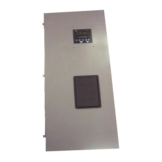
O & M Manual for ATC-300+ 40-400A (480/600Vac)
ATC-300+ 3-Position Contactor Based Transfer Switch
Instruction Booklet
Description
Introduction . . . . . . . . . . . . . . . . . . . . . . . . . . . . . . . . . . 2
Receiving, Handling, and Storage . . . . . . . . . . . . . . . . . . . 6
Equipment Description . . . . . . . . . . . . . . . . . . . . . . . . . . . 7
Installation and Wiring . . . . . . . . . . . . . . . . . . . . . . . . . . .15
Operation . . . . . . . . . . . . . . . . . . . . . . . . . . . . . . . . . . . .21
Testing and Problem Solving . . . . . . . . . . . . . . . . . . . . . . .22
Adjustments . . . . . . . . . . . . . . . . . . . . . . . . . . . . . . . . . .24
Maintenance . . . . . . . . . . . . . . . . . . . . . . . . . . . . . . . . . .24
Renewal Parts Guide . . . . . . . . . . . . . . . . . . . . . . . . . . . .25
ATC-300+ Contactor Based ATS Quick Start Instructions . .26
Appendix A: Pickup / Dropout Tables . . . . . . . . . . . . . . . . .36
IB01602078E
Page
For more information visit: www.generac.com
Advertisement
Table of Contents

Related Manuals for Generac Power Systems ATC-300+


Summary of Contents for Generac Power Systems ATC-300+
-
Page 1: Table Of Contents
O & M Manual for ATC-300+ 40-400A (480/600Vac) ATC-300+ 3-Position Contactor Based Transfer Switch Instruction Booklet Description Page Introduction ........2 Receiving, Handling, and Storage . -
Page 2: Introduction
Instruction Booklet Page 2 Effective: September 2011 40-400A (480/600Vac) ATC-300+ 3-Postion Contactor Based Transfer Switch Section 1: Introduction WARNING 1.1 Preliminary Comments and Safety Precautions READ AND UNDERSTAND THE INSTRUCTIONS CONTAINED HEREIN- This technical document is intended to cover most aspects asso- AFTER BEFORE ATTEMPTING TO UNPACK, ASSEMBLE, OPERATE, ciated with the installation, application, operation, and mainte- OR MAINTAIN THIS EQUIPMENT. - Page 3 Instruction Booklet Effective: September 2011 Page 3 40-400A (480/600Vac) ATC-300+ 3-Postion Contactor Based Transfer Switch 1.2 General Information and the Source 2 power source fails while the Source 1 power source is still unavailable, the ATS remains connected to the Transfer switches are used to protect critical electrical loads Source 2 power source.
- Page 4 Instruction Booklet Page 4 Effective: September 2011 40-400A (480/600Vac) ATC-300+ 3-Postion Contactor Based Transfer Switch Table 1. Withstand Ratings. UL 1008 WITHSTAND AND CLOSE-ON RATINGS (kA) UL 1008 Ampere Rating 480 Volts 600 Volts Specific Specific Breaker Breaker Breaker Breaker 30,000 30,000 22,000...
- Page 5 Instruction Booklet Effective: September 2011 Page 5 40-400A (480/600Vac) ATC-300+ 3-Postion Contactor Based Transfer Switch Table 2. Transfer Switch Catalog Number Explanation POSITIONS 1 TO 2 POSITION 3 POSITION 4 POSITIONS 5 TO 6 BASIC DEVICE SWITCHING DEVICE CONTROL PANEL SWITCHING DEVICE Automatic Transfer Switch AT Contactor C...
-
Page 6: Receiving, Handling, And Storage
Instruction Booklet Page 6 Effective: September 2011 40-400A (480/600Vac) ATC-300+ 3-Postion Contactor Based Transfer Switch Section 2: Receiving, Handling, and 2.3 Storage Storage Although well packaged, this equipment is not suitable for out- door storage. The equipment warranty will not be applicable if 2.1 Receiving there is evidence of outdoor storage. -
Page 7: Equipment Description
Instruction Booklet Effective: September 2011 Page 7 40-400A (480/600Vac) ATC-300+ 3-Postion Contactor Based Transfer Switch Section 3: Equipment Description 3.1 General The ATS consists of three basic panels: 1. The power panel; 2. The voltage selection and transformer panel (if required); and 3. - Page 8 Instruction Booklet Page 8 Effective: September 2011 40-400A (480/600Vac) ATC-300+ 3-Postion Contactor Based Transfer Switch Figure 8. ATC-300+ Logic Control Panel. The ATC-300+ controller has an operating temperature of -20 to 70°C (-4 to 158°F). Figure 7. Standard Voltage Selection Terminals (Shown The controller circuit board is protected by an insulating confor- Connected to the 480 Vac Taps).
- Page 9 Instruction Booklet Effective: September 2011 Page 9 40-400A (480/600Vac) ATC-300+ 3-Postion Contactor Based Transfer Switch 3.5 Features 5H. Phase Reversal For a 3-phase wye source, this feature monitors the phase A variety of standard and optional features are available for Gen- sequence of the sources.
- Page 10 Instruction Booklet Page 10 Effective: September 2011 40-400A (480/600Vac) ATC-300+ 3-Postion Contactor Based Transfer Switch 5L. Source 2 3-Phase Voltage Unbalance 12. Power Source Annunciation For a 3-phase wye source, this feature monitors phase volt- This feature provides LEDs to give switch position and age ratios.
- Page 11 Instruction Booklet Effective: September 2011 Page 11 40-400A (480/600Vac) ATC-300+ 3-Postion Contactor Based Transfer Switch 23K. Plant Exerciser Selectable – Disabled/1/7/14/28 Day Inter- 26L. Source 1 3-Phase Voltage Unbalance .For a 3-phase wye source, this feature monitors phase This feature provides for automatic test operation of the voltage ratios.
- Page 12 Instruction Booklet Page 12 Effective: September 2011 40-400A (480/600Vac) ATC-300+ 3-Postion Contactor Based Transfer Switch Emergency Inhibit (new feature) 14D. Source 2 Present: Provides four (4) normally open and four (4) normally closed contacts. The relay is energized when This feature enables the Emergency inhibit control input to Source 2 is available.
- Page 13 Instruction Booklet Effective: September 2011 Page 13 40-400A (480/600Vac) ATC-300+ 3-Postion Contactor Based Transfer Switch 3.6 Enclosure 23L. 24 Hour, 7day, 365 Day Programmable Plant Exerciser This plant exerciser has two channel electronic time The rugged steel ATS enclosure is supplied with three door switches with 365-day, 7-day, 24-hour programming.
- Page 14 Instruction Booklet Page 14 Effective: September 2011 40-400A (480/600Vac) ATC-300+ 3-Postion Contactor Based Transfer Switch 3.7 Standards The rear of the enclosure is supplied with teardrop shaped holes in the top and bottom mounting flanges to facilitate mounting. It is also supplied with two positioning bolts Generac ATS equipment, enclosed in any of the enclosures listed and various pre-tapped inserts to insure proper positioning in Table 3, is listed for application by UL and ULC.
-
Page 15: Installation And Wiring
Instruction Booklet Effective: September 2011 Page 15 40-400A (480/600Vac) ATC-300+ 3-Postion Contactor Based Transfer Switch Section 4: Installation and Wiring 4.3 Mounting Procedure 4.1 General CAUTION Generac ATSs are factory wired and tested. Installation requires SINCE THE ENCLOSED ATS MUST BE LIFTED INTO PLACE FOR solidly mounting the enclosed unit and connecting power cables MOUNTING, BE CERTAIN THAT ADEQUATE RESOURCES ARE and auxiliary pilot circuits. - Page 16 Instruction Booklet Page 16 Effective: September 2011 40-400A (480/600Vac) ATC-300+ 3-Postion Contactor Based Transfer Switch 4.4 Power Cable Connections With the enclosed ATS equipment unpacked and ready for mounting, proceed with the following steps. Step 1: The ATS enclosure door is hinge mounted with remov- WARNING able hinge pins.
- Page 17 Instruction Booklet Effective: September 2011 Page 17 40-400A (480/600Vac) ATC-300+ 3-Postion Contactor Based Transfer Switch Table 4. Transfer Switch Equipment Wire Sizes TRANSFER SWITCH AMPERE RATING WIRE SIZE RANGES NUMBER OF CABLES PER PHASE TERMINAL TEMPERATURE RATING °C (°F) #14-2/0 75 (167) #6-250 KCMIL 75 (167)
- Page 18 Instruction Booklet Page 18 Effective: September 2011 40-400A (480/600Vac) ATC-300+ 3-Postion Contactor Based Transfer Switch RS485 Termination RS-485 S1 - Line MODBUS Control S1 - Neut Power S2 - Line S2 - Neut Gnd Programming Port Phase C Phase C Source 1 Source 1 Phase B...
- Page 19 Instruction Booklet Effective: September 2011 Page 19 40-400A (480/600Vac) ATC-300+ 3-Postion Contactor Based Transfer Switch 4.7 Voltage Selection Adjustments Certain devices, such as the Voltage Selection Panel, sensing relays, and timers, need to be set and/or calibrated prior to plac- ing the ATS equipment in service.
- Page 20 Instruction Booklet Page 20 Effective: September 2011 40-400A (480/600Vac) ATC-300+ 3-Postion Contactor Based Transfer Switch 4.8 Terminal Block Wire Installation and Removal Proceed with the following steps and associated figures to install or remove terminal block wiring. Step 1: Figure 14 shows two tension clamp terminal blocks. There is a large one and small one, but the operation is the same for both.
-
Page 21: Operation
Instruction Booklet Effective: September 2011 Page 21 40-400A (480/600Vac) ATC-300+ 3-Postion Contactor Based Transfer Switch Section 5: Operation 5.1 General An ATS provides a power contactor to connect and disconnect the load to and from the Source 1 and Source 2 power sources (Section 3.2.1). -
Page 22: Testing And Problem Solving
Instruction Booklet Page 22 Effective: September 2011 40-400A (480/600Vac) ATC-300+ 3-Postion Contactor Based Transfer Switch Section 6: Testing and Problem Solving 5.3 Automatic Transfer The operating sequence of an ATS is dictated by the switch's 6.1 Testing standard features and selected options. Operation of an ATS dur- ing Source 1 power source failure and Source 1 power source After the ATS equipment is initially installed or during planned restoration will be described here with only standard options... - Page 23 Instruction Booklet Effective: September 2011 Page 23 40-400A (480/600Vac) ATC-300+ 3-Postion Contactor Based Transfer Switch NOTICE WARNING AT THIS POINT, AND PRIOR TO MAKING ANY ATTEMPT TO ENER- DO NOT ATTEMPT TO MANUALLY OPERATE THE ATS WITH THE GIZE THE ATS EQUIPMENT, THE ENGINE-DRIVEN GENERATOR SOURCE 1 POWER SOURCE CONNECTED AND AVAILABLE.
-
Page 24: Adjustments
Instruction Booklet Page 24 Effective: September 2011 40-400A (480/600Vac) ATC-300+ 3-Postion Contactor Based Transfer Switch Section 7: Adjustments Section 8: Maintenance 7.1 General 8.1 Introduction Refer to I.B. 01602009E, supplied with the ATS for ATC-300+ WARNING Controller adjustments and programming. HIGH VOLTAGES ARE PRESENT IN AND AROUND ATS EQUIPMENT. -
Page 25: Renewal Parts Guide
Instruction Booklet Effective: September 2011 Page 25 40-400A (480/600Vac) ATC-300+ 3-Postion Contactor Based Transfer Switch SECTION 9: RENEWAL PARTS GUIDE 9.1 General Example: To order the ATC-300+ Controller for an ATC3C3X30400WRU transfer switch, order Catalog Refer to Figure 19 for assistance with selecting and ordering Number as shown in Figure 19, below. - Page 26 Instruction Booklet Page 26 Effective: September 2011 40-400A (480/600Vac) ATC-300+ 3-Postion Contactor Based Transfer Switch Section 10: ATC-300+ Controlled ATS Quick Start Instructions WARNING THESE QUICK START INSTRUCTIONS ARE NOT A COMPLETE SOURCE OF INFORMATION ON THE ATC-300+ CONTROLLED ATS EQUIPMENT.
- Page 27 Instruction Booklet Effective: September 2011 Page 27 40-400A (480/600Vac) ATC-300+ 3-Postion Contactor Based Transfer Switch VOLTAGE SELECTION AND TRANSFORMER PANEL LOGIC PANEL NORMAL LUGS GROUND CONNECTION TRANSFER MECHANISM NEUTRAL CONNECTION EMERGENCY LUGS LOAD LUGS Figure 21. 400A, 3-Pole, ATS Interior Components. IB01602078E For more information visit: www.generac.com...
- Page 28 Instruction Booklet Page 28 Effective: September 2011 40-400A (480/600Vac) ATC-300+ 3-Postion Contactor Based Transfer Switch Step 3: Turn the generator OFF at the generator control panel. the engine generator is needed, and should be connected This will prevent unexpected activation of the generator. to a generator controller.
- Page 29 Instruction Booklet Effective: September 2011 Page 29 40-400A (480/600Vac) ATC-300+ 3-Postion Contactor Based Transfer Switch Unit Status ATC-300 Available Source 1 Connected Load Available Connected Source 2 Help Step Engine Lamp Test Enter Test Alarm Bypass Reset TDNE / TDEN Figure 23.
- Page 30 Instruction Booklet Page 30 Effective: September 2011 40-400A (480/600Vac) ATC-300+ 3-Postion Contactor Based Transfer Switch Utility - Generator Transfer Switch Source 1 is available Close Source 1 (Energize K1) Source 1 is powering the load Source 1 becomes unavailable Is Source 1 (or Engine Test, Plant Exercise, Go To Emergency) Available? TDES timer times out...
- Page 31 Instruction Booklet Effective: September 2011 Page 31 40-400A (480/600Vac) ATC-300+ 3-Postion Contactor Based Transfer Switch Dual Utility Transfer Switch Source 1 is available Close Source 1 (Energize K1) Source 1 is powering the load Source 1 becomes unavailable (or Go To Emergency) Is Source 1 Is Source 2 Available?
- Page 32 Instruction Booklet Page 32 Effective: September 2011 40-400A (480/600Vac) ATC-300+ 3-Postion Contactor Based Transfer Switch Table 6. Setpoint Possibilities SETPOINT SETPOINT UNITS DESCRIPTION RANGE FACTORY DEFAULT New Password Four Digits Set New Password 0000 to 9999 0300 TDES Minutes: Seconds Time Delay Engine Start 0 to 120 seconds 0:03...
- Page 33 Instruction Booklet Effective: September 2011 Page 33 40-400A (480/600Vac) ATC-300+ 3-Postion Contactor Based Transfer Switch Table 6. Setpoint Possibilities (cont’) SETPOINT SETPOINT UNITS DESCRIPTION RANGE FACTORY DEFAULT PE DAY Days Plant Exerciser Day of the Week 1 SUN, 2 MON, 3 TUE, 4 WED, 5 THU, 6 FRI or 7 SAT PE HOUR Hours Plant Exerciser Hour...
- Page 34 Instruction Booklet Page 34 Effective: September 2011 40-400A (480/600Vac) ATC-300+ 3-Postion Contactor Based Transfer Switch Step 7: To change or add a setpoint, select Yes when the “Change Setpoints” message appears on the screen. WARNING Use the <Step/Enter> pushbutton to step through the setpoints.
- Page 35 Instruction Booklet Effective: September 2011 Page 35 40-400A (480/600Vac) ATC-300+ 3-Postion Contactor Based Transfer Switch Step 10: ATC3 Controlled ATS Power Failure Test - Initiate a Load Test by simulating an actual power failure. 1. This should be done by opening the upstream Unit Status breaker or fused disconnect switch.
-
Page 36: Appendix A: Pickup / Dropout Tables
Instruction Booklet Page 36 Effective: September 2011 40-400A (480/600Vac) ATC-300+ 3-Postion Contactor Based Transfer Switch Appendix A: Pickup / Dropout Tables UNDERVOLTAGE PICKUP / DROPOUT TABLE PERCENTAGE VOLTAGE Pickup Dropout For more information visit: www.generac.com IB01602078E... - Page 37 Instruction Booklet Effective: September 2011 Page 37 40-400A (480/600Vac) ATC-300+ 3-Postion Contactor Based Transfer Switch OVERVOLTAGE PICKUP / DROPOUT TABLE PERCENTAGE VOLTAGE Dropout Pickup UNDERFREQUENCY PICKUP / DROPOUT TABLE PERCENTAGE FREQUENCY Pickup Dropout OVERFREQUENCY PICKUP / DROPOUT TABLE PERCENTAGE FREQUENCY Dropout Pickup IB01602078E...
- Page 38 Instruction Booklet Page 38 Effective: September 2011 40-400A (480/600Vac) ATC-300+ 3-Postion Contactor Based Transfer Switch Notes: For more information visit: www.generac.com IB01602078E...
- Page 39 Instruction Booklet Effective: September 2011 Page 39 40-400A (480/600Vac) ATC-300+ 3-Postion Contactor Based Transfer Switch Notes: IB01602078E For more information visit: www.generac.com...
- Page 40 (ICBO). UL is a federally registered trademark of the Underwriters Laboratories Inc. Generac Power Systems, Inc. S45 W29290 Hwy. 59 Waukasha, WI 53189 1-888-GENERAC (1-888-436-3722) generac.com © 2011 Generac Power Systems, Inc. All Rights Reserved Printed in USA Publication No. IB01602078E/TBG00610 September 2011...
Need help?
Do you have a question about the ATC-300+ and is the answer not in the manual?
Questions and answers