
Related Manuals for Generac Power Systems Power Zone 410


Summary of Contents for Generac Power Systems Power Zone 410
- Page 1 ® Technical Manual ® Power Zone 410 Controller AUXILIARY SHUTDOWN SAVE THIS MANUAL FOR FUTURE REFERENCE...
- Page 2 WARNING CANCER AND REPRODUCTIVE HARM www.P65Warnings.ca.gov. (000393a) Technical Manual Power Zone 410 Controller...
-
Page 3: Table Of Contents
Controller ............ 8 Navigation ............9 Screens ............9 Wizard Screens..........9 Engine Screen..........11 Power Screen..........11 Setting Screen..........12 Dealer Screen ..........13 Info Screen............16 Alarm Screen ..........17 Modify a Page Setting ........18 Technical Manual Power Zone 410 Controller... - Page 4 This page intentionally left blank. Technical Manual Power Zone 410 Controller...
-
Page 5: Section 1: Introduction And Safety
Introduction and Safety Section 1: Introduction and Safety Introduction Thank you for purchasing a Generac Power Systems Inc. DANGER product. This unit has been designed to provide high- performance, efficient operation, and years of use when Indicates a hazardous situation which, if not avoided, maintained properly. -
Page 6: General Hazards
(000229) vision loss. (000101) WARNING Vision loss. Eye protection is required when servicing unit. Failure to do so could result in vision loss or serious injury. (000377) Technical Manual Power Zone 410 Controller... -
Page 7: Fire And Explosion Hazards
Failure to do so will result in death or serious injury. (000152) WARNING Electrical shock. Disconnect battery ground terminal before working on battery or battery wires. Failure to do so could result in death or serious injury. (000164) Technical Manual Power Zone 410 Controller... - Page 8 Introduction and Safety This page intentionally left blank. Technical Manual Power Zone 410 Controller...
-
Page 9: Section 2: General Information
Section 2: General Information • Introduction Selectable Low Speed Exercise • NFPA 110 Capable** The Power Zone 410 Control Panel is an electronic con- • 5 A Integrated Battery Charger*** trol box that functions as an advanced standby generator controller. Standard Protections... -
Page 10: Control Panel
Speed Control through ECM Integration • Soft Start Ramping (Multiple Steps) The Power Zone 410 Control Panel controller is setup in the factory to match the product it is shipped with and Communication Ports generally no changes are required. For spares purposes the controller can be re-configured in the field using Dis- •... -
Page 11: Engine Management
Load Accept Voltage - The generator must reach this voltage before issuing the “Accept load” signal. Table 2-1. Engine Settings Number Parameter Units Preheat Time (S)econds Start Detection RPM Crank Time Alarm Hold-Off Time Engine Warm Up Time Target Frequency Technical Manual Power Zone 410 Controller... -
Page 12: Starting And Stopping Sequence Diagrams
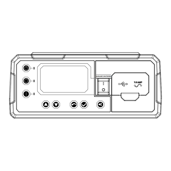
NOTE: A Remote Start signal will terminate exercise and Figure 2-3. Front Panel Display proceed to normal running mode. AUTO mode STOP mode MANUAL mode Navigation arrows ESCAPE ENTER SILENCE Auxiliary shutdown USB port and 7.5 A fuse Technical Manual Power Zone 410 Controller... -
Page 13: Navigation
To activate go to The Wizard Screens are displayed at controller startup. www.activategen.com Figure 2-5. Use page 1 to set the language for the xxxxxxxxxx screens. Code xxxxx 012981 Figure 2-7. Wizard Screen (Page 3) Technical Manual Power Zone 410 Controller... - Page 14 Install Wizard Parameter Group Set Exercise Config Quiet Test hh:mmxx Monthly xxxxxxxxx Duration: xx Min Xfer: xxxxx 012984 Figure 2-10. Wizard Screen (Page 6) 012987 Figure 2-13. Wizard Screen (Page 9) Technical Manual Power Zone 410 Controller...
-
Page 15: Engine Screen
2-16. Page 3 displays the battery volts, inter- nal battery charge amps, external battery charger status (OFF = not connected, ON = connected), and battery condition for the battery charger. 012992 Figure 2-18. Power Screen (Page 2) Technical Manual Power Zone 410 Controller... -
Page 16: Setting Screen
The pages within the Setting Screen contain settings that can be modified by the user. To modify a page setting see Modify a Page Setting. Figure 2-22. Use page 1 to adjust unit voltage, and set language, date/time, and exercise schedule. Technical Manual Power Zone 410 Controller... -
Page 17: Dealer Screen
Enable Dual Fuel Dealer Edit: Startup Delay Return Delay 013004 Util Loss Volts Figure 2-30. Edit Settings (Page 4) Util Pickup Volts 013001 Figure 2-27. Edit Settings (Page 1) Technical Manual Power Zone 410 Controller... - Page 18 Dealer Edit: Dealer Test: Low Oil Pressure Digital Inputs Parameter Group Digital Outputs Voltage Code Analog Channels Fuel Level Indicators 013006 013009 Figure 2-33. Edit Settings (Page 6) Figure 2-36. Test (Page 1) Technical Manual Power Zone 410 Controller...
- Page 19 Figure 2-38. Calibrate (Page 1) Figure 2-39. Use page 2 to calibrate generator amps. 013014 Figure 2-41. Gateway (Page 1) Dealer Calibrate: Gen. Amps A Gen. Amps B Gen. Amps C 013012 Figure 2-39. Calibrate (Page 2) Technical Manual Power Zone 410 Controller...
-
Page 20: Info Screen
No Log To Display Alarm Log: 04/19/21 10:59pm Very Low Battery 013019 ECODE 2751 Figure 2-45. Maintenance Log 013017 Figure 2-43. Alarm Log Technical Manual Power Zone 410 Controller... -
Page 21: Alarm Screen
Bootloader x.xx Firmware x.xx Firmware Build xxxx ECODE Active Fault 2801 Aux Shutdown 2710 Ruptured Tank 013022 Battery Maint Due Figure 2-48. General Info (Page 3) 013025 Figure 2-51. Alarm Screen (Page 1) Technical Manual Power Zone 410 Controller... -
Page 22: Modify A Page Setting
To confirm the change, press the ENTER button until the previous page is displayed as shown in 2-52. To cancel the change, press the Figure ESCAPE button ( ) until the previous page is displayed. Technical Manual Power Zone 410 Controller... -
Page 23: Section 3: Input/Output And Connector Information
Connection Spare Analog Output 0 to 10 V J10-10 (signal) J10-11 (return) Digital Inputs Default Signal Name Range/Level Connection Coolant Level 0 to 5 V (switched 5 V J5-23 coolant+ clock signal) J5-24 coolant- Technical Manual Power Zone 410 Controller... -
Page 24: Digital Outputs
Open collector with 240 Ω resistor TriclopsGRN Open collector with 240 Ω resistor TriclopsRED Open collector with 240 Ω resistor Triclops+5V +5 V for Triclops with 50 mA fuse DualFuel1/Low Fuel Lvl NG/LO_FUEL (open drain) Technical Manual Power Zone 410 Controller... -
Page 25: Can/Current/Analogs
Dry contact – E-Stop In Dry contact – KeyswitchPresent(in) 5 V pullup – KeyswitchPresent(gnd) – – +12V Alarm – – Audible Alarm open drain – Keyswitch(1) 5 V pullup – Keyswitch(2) 5 V pullup – Technical Manual Power Zone 410 Controller... -
Page 26: Power/Relays
+3.3 V Position Ret filtered GND – – – Speed(12V) +12 V supply – Throttle Enable open drain Throttle PWM open drain – – – Speed(ret) – – Speed(signal) Speed input signal – Technical Manual Power Zone 410 Controller... -
Page 27: Comms1
– FIELD(+) – J11 16 Pin Signal Board Connection Description Wire # VBUS Switch +5 V VBUS – USB D(-) – – USB D(+) – – – – Shield – – Shield – – Technical Manual Power Zone 410 Controller... -
Page 28: Voltages
UTIL A – UTIL B – UTIL C – CHARGER J7 2 Pin Signal Board Connection Description Wire # Do not connect if ext charger used Neutral Do not connect if ext charger used Technical Manual Power Zone 410 Controller... -
Page 29: Section 4: Internal Alarms/Warnings
Over 75 Hz for one second with the throttle stuck open, total loss of control. Possible causes: Stuck throttle 1207 Overspeed Instantaneous—Over 75 Hz for 150 milliseconds based on measuring zero cross to zero cross times. Technical Manual Power Zone 410 Controller... - Page 30 Underspeed Unit Overloaded or Fuel System issue <83.3% speed (60 Hz) or <66.6% speed (50 Hz) for 30 seconds. Unit is overloaded slowing engine speed. Possible cause: highly inductive loads, actuator, or fuel supply. Technical Manual Power Zone 410 Controller...
- Page 31 3 Wire Start NO NC switches are not in desired position. Position Error 2070 Keypad Missing Keypad is missing. 2098 Wire Error Miswired—Generator Xfer Enabled Output has been miswired. 2099 Wire Error Miswired—Incorrect DC AC wiring hook up. Technical Manual Power Zone 410 Controller...
- Page 32 2616 Over current Coil current too high for one second. cylinder6 2617 Over current Coil current too high for one second. cylinder7 2618 Over current Coil current too high for one second. cylinder8 Technical Manual Power Zone 410 Controller...
- Page 33 No response from I/O Extender for 3 seconds after a hold-off duration of 30 Comm seconds. 2678 I/O Ext. 4 Loss of No response from I/O Extender for 3 seconds after a hold-off duration of 30 Comm seconds. Technical Manual Power Zone 410 Controller...
- Page 34 The system detected the E-Stop button was pressed and shutdown. E-Stop can AUX Shutdown also be set for AUX shutdown. 2802 External Common System detected a common shutdown alarm indicator true for 1 second from Alarm - 1 one of the configured I/O Extender modules. Technical Manual Power Zone 410 Controller...
- Page 35 Fuel Pressure Fault—Voltage below normal range; shorted to low source; open 3204 Engine Fuel Deliv- circuit. ery Pressure 3215 Engine Fuel Deliv- High Fuel Pressure—Data valid but above normal operating range; least severe level. ery Pressure Technical Manual Power Zone 410 Controller...
- Page 36 Low MAP Temp—Data valid but below normal operating range; least severe level. ifold 1 Temperature 3600 Engine Air Filter 1 Check Air Filter—Data valid but above normal operating range; high severe level. Differential Pres- sure Technical Manual Power Zone 410 Controller...
- Page 37 Oil Temp Fault—Voltage above normal range; shorted to high source. 3904 Engine Oil Tem- perature 1 3915 Engine Oil Tem- High Oil Temp—Voltage below normal range; shorted to low source; open circuit. perature 1 Technical Manual Power Zone 410 Controller...
- Page 38 Engine Knock Sensor Fault—Data valid but below normal operating range; high severe level. 4402 Engine Knock 1 Engine Knock Sensor Fault—Data erratic, intermittent, or incorrect. Engine Knock Sensor Fault—Voltage above normal range; shorted to high 4403 Engine Knock 1 source. Technical Manual Power Zone 410 Controller...
- Page 39 Fuel Mixer—Data valid but below normal operating range; high severe level. 1 Position 4902 Engine Fuel Valve Fuel Mixer—Data erratic, intermittent, or incorrect. 1 Position 4903 Engine Fuel Valve Fuel Mixer—Voltage above normal range; shorted to high source. 1 Position Technical Manual Power Zone 410 Controller...
- Page 40 RPM Fault—Mechanical system not responding correctly. 5107 Engine Speed 5115 Engine Speed RPM High—Data valid but above normal operating range; least severe level. RPM Low—Data valid but below normal operating range; least severe level. 5117 Engine Speed Technical Manual Power Zone 410 Controller...
-
Page 41: Section 5: Ground Fault Indication (If Equipped)
Indication feature, located by selecting the Dealer Screen ) → Edit Settings → Ground Fault. Power Zone 410 generators have CTs on all phases to provide phase current measurements. This data is used to calculate system current, powers, and PF (power fac- tor). - Page 42 Ground Fault Indication (If Equipped) This page intentionally left blank. Technical Manual Power Zone 410 Controller...
- Page 44 ©2022 Generac Power Systems, Inc. S45 W29290 Hwy. 59 All rights reserved. Waukesha, WI 53189 Specifications are subject to change without notice. 1-888-GENERAC (1-888-436-3722) No reproduction allowed in any form without prior written www.generac.com consent from Generac Power Systems, Inc.
Need help?
Do you have a question about the Power Zone 410 and is the answer not in the manual?
Questions and answers
How to reset after it codes
To reset the Generac Power Systems Power Zone 410 after it shows a code, follow these steps:
1. Identify the Code – Check the displayed fault code to understand the issue.
2. Resolve the Issue – Address the underlying problem, such as fuel pressure issues or internal faults.
3. Reboot the Controller – Some faults, like watchdog timeouts or exceptions, trigger an automatic reboot.
4. Manually Reset if Needed – If the controller does not reset automatically, power cycle the system by turning it off and on.
5. Re-enter Activation Code – If prompted, enter the correct activation code within three attempts.
6. System Update – If the issue persists due to a software problem, complete the system update process.
If the issue remains unresolved, contact an IASD (Independent Authorized Service Dealer).
This answer is automatically generated
how to clear active faults on the Generac Powerzone 410