
Related Manuals for Generac Power Systems Power Zone Pro


Summary of Contents for Generac Power Systems Power Zone Pro
- Page 1 ® Owner’s Manual ® Power Zone Pro Main Controller SAVE THIS MANUAL FOR FUTURE REFERENCE...
- Page 2 WARNING CANCER AND REPRODUCTIVE HARM www.P65Warnings.ca.gov. (000393a) Owner’s Manual for Power Zone Pro Main Controller...
-
Page 3: Table Of Contents
Module Power Supply Wiring ........12 Analog Sensor Power Supply Wiring ......12 Digital Inputs (DI) ............12 Digital Outputs (DO) ..........12 High Current Digital Output ........12 General Purpose Analog Inputs (GPAI) ....12 Special Analog Inputs ..........13 Owner’s Manual for Power Zone Pro Main Controller... - Page 4 This page intentionally left blank. Owner’s Manual for Power Zone Pro Main Controller...
-
Page 5: Section 1 Introduction And Safety
The manufacturer also strongly recommends instructing other users on how to properly start and operate the unit. This prepares them if they need to operate the equipment in an emergency. Owner’s Manual for Power Zone Pro Main Controller... -
Page 6: Safety Rules
Electric shock. Only a trained and licensed electrician should perform wiring and connections to unit. Failure to follow proper installation requirements could result in death, serious injury, and equipment or property damage. (000155a) Owner’s Manual for Power Zone Pro Main Controller... -
Page 7: Section 2 General Information
V/F - Voltage per Frequency Algorithm bps - Bits per Second DC Voltage ECU - Engine Control Unit CT - Current Transformer NFPA - National Fire Protection Association BMS - Building Management System Owner’s Manual for Power Zone Pro Main Controller... -
Page 8: Connections
(BS7) J7 Generac CAN, watchdog digital (BS2) J2 digital outputs output, peripheral module power (BS1) battery connection, 12 V reference, RPM, RS- (BS8) J8 J1939 CAN Owner’s Manual for Power Zone Pro Main Controller... -
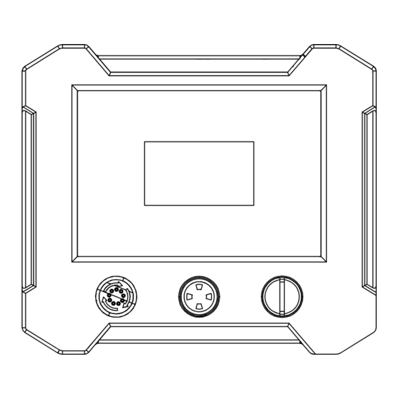
Page 9: Dimensions
9.45 in (240.0 mm) 2.24 in (57.0 mm) 10.71 in (272.1 mm) 2.67 in (67.7 mm) NOTE: Dimensions shown are for reference only, and may vary depending on generator size and application. Owner’s Manual for Power Zone Pro Main Controller... -
Page 10: Features
Diagnostics NOTE: Actual I/O may vary due to configuration. • Maintenance Events/Information • Engine Run Hours Qualification Testing • Life Test in Environmental Chamber • Temperature Rating • Vibration Tested and Protected Owner’s Manual for Power Zone Pro Main Controller... -
Page 11: Codes And Standards
Phase to Phase and Phase to Neutral Short Circuits. (I T Algorithm and GFI) Control Panel and Touch Screen • Auto/Manual/Off Key Switch • Alarm Acknowledge Soft Key • Audible Alarm • Emergency Stop Owner’s Manual for Power Zone Pro Main Controller... -
Page 12: Specifications
0 V to 5 V (10 uA max), 0 V to 10 V (10 uA max); Resistive, 500 Hz Analog Output 0 V to 5 V, 0 V to 10 V, 10 mA max Others Installation and Operation Owner’s Manual for Power Zone Pro Main Controller... - Page 13 Maximum input current <1 mA Sampling Rate >1 kHz Coolant Level Special Analog Input (1) Number of inputs Input type Special analog Sensor impedance, uncovered 562 Kohm (typical) Maximum sensor current 0.1 mA Owner’s Manual for Power Zone Pro Main Controller...
- Page 14 NOTE: The communications cables should not be run in the same conduit or in the same wire grouping as any high voltage or high current conductors. NOTE: The communications baud rates should be selected to be compatible with other components connected to the communications bus. Owner’s Manual for Power Zone Pro Main Controller...
-
Page 15: Section 3 Installation And Operation
Main Controller to the ECU. The shield should 009395 be connected at the Main Controller end only. Each end Figure 3-1. Mounting and Grounding of the CAN bus must be terminated with appropriate Owner’s Manual for Power Zone Pro Main Controller... -
Page 16: Can Bus And Rs-485 Termination Resistor
Usually a sensor is either two or three wire. Two wire terminal block. #16 gauge wires are recommended for sensors present a resistance to the Main Controller and these connections. are wired between ground and the analog input pin. Owner’s Manual for Power Zone Pro Main Controller... -
Page 17: Special Analog Inputs
Current Transformers (CT’s). These need to be appropriately sized for the generator. The CT should be rated for 300% of the generator rated current (example: 100 amp CT must be able to measure at least 300 amps) Owner’s Manual for Power Zone Pro Main Controller... -
Page 18: Analog Outputs
For example the voltage sensing is performed within the generator enclosure, but there may be voltage drops in the external cabling/switchgear that need to be taken into account. Owner’s Manual for Power Zone Pro Main Controller... -
Page 19: Pin Map
(BS1) J1-17 Mag Pickup Shield Primary Mag Pickup Sensor Engine Speed SHLD (BS1) J1-18 Battery (-) Negative Battery Connection (BS1) J1-19 Battery (-) Negative Battery Connection (BS1) J1-20 Battery (-) Negative Battery Connection Owner’s Manual for Power Zone Pro Main Controller... - Page 20 AVR Trigger B - PWMO #6 (BS2) J2-21 DOUT21 Digital Out - Configurable A/F Solenoid/PWMO #7 (2A) 808/A (BS2) J2-22 N.C. No Connection (BS2) J2-23 12 V Analog Sensor Supply (BS2) J2-24 12 V Analog Sensor Supply Owner’s Manual for Power Zone Pro Main Controller...
- Page 21 Ground for Analog/Digital Aux Input #1 Sensor (-) AI1R (BS3) J3-23 Ground Ground for Analog/Digital Aux Input #2 Sensor (-) AI2R (BS3) J3-24 Ground Ground for Analog/Digital Oil Pressure #2 Sensor (-) 69R2 Owner’s Manual for Power Zone Pro Main Controller...
- Page 22 Coolant Temp Sensor #2 (-) 68R2 (BS4) J4-21 Analog Sensor Supply Oil Pressure #1 Supply 69V1 (BS4) J4-22 Analog Sensor Supply Oil Pressure #2 Supply 69V2 (BS4) J4-23 Analog Sensor Supply (BS4) J4-24 Analog Sensor Supply Owner’s Manual for Power Zone Pro Main Controller...
- Page 23 Digital Input or PWMI 5. Aux In #8 PWMI #5 (BS5) J5-14 Configurable DIN15 Digital Input or PWMI 6. AVR ZC - PWMI #6 (BS5) J5-15 Configurable (BS5) J5-16 N.C. No Connection Owner’s Manual for Power Zone Pro Main Controller...
- Page 24 (BS8) J8-2 ECU J1939 Ground ECU J1939 CAN Ground SHLD (BS8) J8-3 ECU J1939 CAN (+) ECU J1939 CAN High 743A (BS8) J8-4 ECU J1939 CAN (-) ECU J1939 CAN Low 744A Owner’s Manual for Power Zone Pro Main Controller...
-
Page 25: Operation
Utility Phase C Voltage Sense Operation Analog Sensor Failure The Power Zone Pro Main Controller serves as a single Analog sensors can have sensor fault checks enabled. standby generator controller. These checks detect a raw analog input value outside of the normally expected values for the sensor. -
Page 26: Short Circuit
“soft contacts”, the output of one rung can be fed into the input of another to provide more combinations. As well as the logical combinations, there are also analog comparisons, counters and timers available for use in the rungs. Owner’s Manual for Power Zone Pro Main Controller... -
Page 27: Top Banner
Alternator down to show more data. Figure 3-5 shows how scrolling on the “Engine” page brings up more engine bargraphs. System Details More Owner’s Manual for Power Zone Pro Main Controller... -
Page 28: Bargraphs
If there is any alarm AND the bottom banner is displaying Owner’s Manual for Power Zone Pro Main Controller... -
Page 29: Date And Time Format
Connectivity Server. The Connectivity Server provides both viewing and editing capabilities for all generator settings as well as data logging and firmware upgrade capability. See the Connectivity Server manual for more details. Owner’s Manual for Power Zone Pro Main Controller... -
Page 30: Power Zone Pro Menu Map
Installation and Operation Power Zone Pro Menu Map NOTE: Menu structure represents the LCD display and does not follow the browser structure completely. 009405 Figure 3-13. Power Zone Pro Menu Map Owner’s Manual for Power Zone Pro Main Controller... -
Page 31: Section 4 Troubleshooting
Verify the cable connection is a shielded twisted pair. communicate with the Power Verify the shield is grounded at one end of the cable. Zone Pro NOTE: Refer to the Power Zone Pro System manual for additional diagnostic information. Owner’s Manual for Power Zone Pro Main Controller... - Page 32 ©2019 Generac Power Systems, Inc. S45 W29290 Hwy. 59 All rights reserved. Waukesha, WI 53189 Specifications are subject to change without notice. 1-888-GENERAC (1-888-436-3722) No reproduction allowed in any form without prior written www.generac.com consent from Generac Power Systems, Inc.
Need help?
Do you have a question about the Power Zone Pro and is the answer not in the manual?
Questions and answers