Table of Contents
Advertisement
Quick Links
Owner's/Installation Manual
Para español , visita:
http://www.generac.com/service-support/product-support-lookup
Pour le français, visiter :
SAVE THIS MANUAL FOR FUTURE REFERENCE
Owner's/Installation Manual for SMM
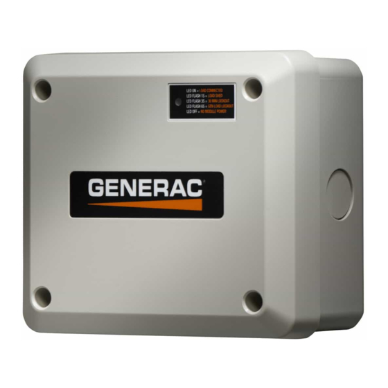
Smart Management Module
MODEL: 006873
DATE PURCHASED:______________
This product is not intended to be used in
a critical life support application. Failure to
adhere to this warning could result in
death or serious injury.
WWW.GENERAC.COM
1-888-GENERAC
http://www.generac.com/service-support/product-support-lookup
(SMM)
000922
WARNING
(1-888-436-3722)
(000209a)
i
Advertisement
Table of Contents
Troubleshooting

Summary of Contents for Generac Power Systems 006873
- Page 1 Owner’s/Installation Manual Smart Management Module (SMM) 000922 MODEL: 006873 DATE PURCHASED:______________ WARNING This product is not intended to be used in a critical life support application. Failure to adhere to this warning could result in death or serious injury. (000209a) WWW.GENERAC.COM...
- Page 2 WARNING California Proposition 65. Engine exhaust and some of its constituents are known to the state of California to cause cancer, birth defects, and other reproductive harm. (000004) WARNING California Proposition 65. This product contains or emits chemicals known to the state of California to cause cancer, birth defects, and other reproductive harm.
-
Page 3: Table Of Contents
Table of Contents Table of Contents Section 1: Introduction and Safety Introduction ............1 Safety Rules ............1 Section 2: General Information and Setup Load Management Options .........3 Application Considerations ........3 Smart Management Module ........3 Smart A/C Module (Inside Transfer Switch) ........3 Know Your Smart Management Module and Carton Contents ...........4 Section 3: Installation, Tests and... - Page 4 Table of Contents This page intentionally left blank. Owner’s/Installation Manual for SMM...
-
Page 5: Section 1: Introduction And Safety Introduction
Section 1: Introduction and Safety Section 1: Introduction and Safety Introduction DANGER Thank you for purchasing a Generac Smart Management Indicates a hazardous situation which, if not avoided, Module. The Smart Management Modules (SMM) are designed to work together to prevent the home standby will result in death or serious injury. - Page 6 Section 1: Introduction and Safety This page intentionally left blank. Owner’s/Installation Manual for SMM...
-
Page 7: Section 2: General Information And Setup
Section 2: General Information and Setup Section 2: General Information and Setup Load Management Options NOTE: For digital thermostats where a 24 VAC thermostat wire is not available, an SMM must be used to Load management systems are designed to work break the power at the HVAC load itself. -
Page 8: Know Your Smart Management Module And Carton Contents
Section 2: General Information and Setup Know Your Smart Management 0 GROUND Module and Carton Contents 194 +12V Priority Dial (A) – Sets module priority. 23 TRANSFER NEUTRAL NOTE: PRIORITY MUST BE DIFFERENT for each module in an installation. Priority sets the order in A/C 1 which loads recover from a load shed event. - Page 9 Section 2: General Information and Setup Table 2-2. Lockout Switch Settings Lockout Switch Mode Function Position GENERATOR Power is NOT available on module output (contactor output). Contactor is OPEN. UTILITY Power is available on module output (contactor output). Contactor is CLOSED. GENERATOR Module operates with standard load shed logic.
- Page 10 Section 2: General Information and Setup Figure 2-4. SMM Sequence of Operations Owner’s/Installation Manual for SMM...
-
Page 11: Section 3: Installation, Tests And Troubleshooting Electrical Specifications
Section 3: Installation, Tests and Troubleshooting Section 3: Installation, Tests and Troubleshooting Electrical Specifications DANGER Electrocution. Turn utility and emergency Input Voltage 240 VAC power supplies to OFF before connecting Current Rating 50A resistive, 40A inductive power source and load lines. Failure to do so will result in death or serious injury. -
Page 12: Connections
Section 3: Installation, Tests and Troubleshooting DANGER Electrocution. Turn utility and emergency power supplies to OFF before connecting power source and load lines. Failure to do so will result in death or serious injury. (000116) Turn both UTILITY (NORMAL) EMERGENCY (STANDBY) power supplies before connecting power source and load lines to transfer switch and SMM. -
Page 13: Setting Lockout
Section 3: Installation, Tests and Troubleshooting An example configuration is shown below. Configurations Once load shed occurs, LED will flash at one will vary depending on customer prioritization of loads: second intervals. Allow time for each module to enable contactor output per priority setting. -
Page 14: Troubleshooting
Section 3: Installation, Tests and Troubleshooting Troubleshooting Table 4 for troubleshooting problems, causes and corrections. Table 4. Troubleshooting Problem Cause Correction Load not powered, LED is OFF Circuit Breaker disabled. Enable Circuit Breaker Load not powered, LED is OFF MLCB disabled and generator OFF. Enable MLCB if utility is present or verify generator operation if outage. - Page 16 Part No. 0K7447 Rev. G 12/23/15 Printed in USA Generac Power Systems, Inc. ©2015 Generac Power Systems, Inc. All rights reserved S45 W29290 Hwy. 59 Specifications are subject to change without notice. Waukesha, WI 53189 No reproduction allowed in any form without prior written 1-888-GENERAC (1-888-436-3722) consent from Generac Power Systems, Inc.


Need help?
Do you have a question about the 006873 and is the answer not in the manual?
Questions and answers