Advertisement
Quick Links
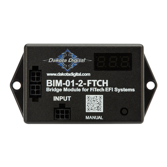
BIM-01-2-FTCH
Bridge Module for FiTech EFI Systems
This Bus Interface Module is designed to read engine information from the FiTech bus. The module is connected to the
FiTech Bus through the 394287 CAN bus-adapter.
There are two interface (I/O) ports on the BIM-01-2-FTCH module. Either one can be connected to the instrument system
or to another module, allowing several units to be daisy chained together.
The information that is available from the unit depends on the ECU programming and add-ons.
*FiTech will be releasing compatibility for AF/R and Boost in an upcoming firmware release. This BIM
unit is pre-programmed to be compatible with these readings once the firmware is released by FiTech*
A GPS-50-2 CANNOT be linked (daisy chained) to a BIM-01-2-FTCH with a BIM cable.
The two units cannot talk to the display control box at the same time.
[1]
MAN #650819A
Advertisement

Summary of Contents for Dakota Digital BIM-01-2-FTCH
- Page 1 This Bus Interface Module is designed to read engine information from the FiTech bus. The module is connected to the FiTech Bus through the 394287 CAN bus-adapter. There are two interface (I/O) ports on the BIM-01-2-FTCH module. Either one can be connected to the instrument system or to another module, allowing several units to be daisy chained together.
-
Page 2: Display Setup
BIM cable from the Bus Interface Module. The BIM menu of the display will not find the BIM-01-2-FTCH, but will find specific channels for Boost and Air/Fuel Ratio. The following settings are for the basic information to be displayed with data from the BIM module. - Page 3 Tap SW1 until and DONE are displayed. • Press and hold SW1 until “-” and DONE are displayed. Obtaining engine temperature from the BIM-01-2-FTCH • Hold the SW1 switch from the instrument system control box while turning the key on.
- Page 4 Tap SW1 (I) until TACH DONE is displayed. • Press and hold SW1 (I) until a big DONE is displayed. Obtaining engine temperature from the BIM-01-2-FTCH • Hold the SW1 (I) switch from the instrument system control box while turning the key on.
- Page 5 HDX and RTX setup: **HDX/RTX systems can be configured with the Dakota Digital app for Apple and Android devices** HDX and RTX Operations • HDX: With the ignition key already on, press and hold both switches to enter SETUP, release when instructed.
- Page 6 GRAFIX setup: **GRAFIX systems can be configured with the Dakota Digital app for Apple and Android devices** GRAFIX Operations • With the vehicle stopped, tap the Control Knob to enter the Main Menu The Main menu can be entered with the vehicle moving, but only the speedometer ADJUST menu will be available in the SETUP menu •...
- Page 7 NOTE: The “Send to ECU” button will only enable the currently highlighted CAN output. This step must be repeated for every CAN output that you wish to enable. If the CAN output for a respective reading is not enabled, the BIM-01-2-FTCH will not receive these readings from the FiTech bus.
- Page 8 (FiTech will be releasing compatibility for this reading in an upcoming Firmware release) The BIM-01-2-FTCH has an option to monitor Air Fuel Ratio. • Hold the switch on the BIM-01-2-FTCH case while turning the key on. The BIM display will show the current revision code while this is held. •...
-
Page 9: Quick Tips
“” - Boost/Vacuum data “” - RPM/Tachometer data If you do not see any number of these listed, the data may not be transmitted for the BIM-01-2-FTCH to read. Emissions note: If your vehicle requires emissions testing in your area, the check engine feature of this unit cannot be used to operate the Check Engine or Service Engine indicator. -
Page 10: Troubleshooting Guide
Troubleshooting guide: Problem Possible cause Solution No BIM data on instrument readout; PWR wire does not have power. Connect to a location that has +12V key-on power. BIM does not light up. GND wire is not properly grounded. Connect to a different ground location. Power/data harness is damaged. - Page 11 Notes: [11] MAN #650819A...
-
Page 12: Service And Repair
This Warranty is in lieu of all other expressed warranties or liabilities. Any implied warranties, including any implied warranty of merchantability, shall be limited to the duration of this written warranty. No person or representative is authorized to assume, for Dakota Digital, any liability other than expressed herein in connection with the sale of this product.


Need help?
Do you have a question about the BIM-01-2-FTCH and is the answer not in the manual?
Questions and answers