Advertisement
This Bus Interface Module connects to a solid state pressure sensor. There are two power & data interface (I/O) ports on
the module. Either one can be connected to the gauge system or to another module, allowing several units to be daisy
chained together. Do not connect the I/O port to anything other than a Dakota Digital gauge or BIM. Do not mount the
module in the engine compartment; it should be mounted in interior of the vehicle.
Each unit connected to the bus needs a unique ID number assigned to it. The unit comes preset with an ID value that
should not conflict with any other BIM connected to your system. If needed the ID can be automatically reset to an
unused value. The factory default label is PSI, but this can be changed in the gauge setup.
Labels available for each input are:
generic pressure input. This will display PSI x, Px, or PRESSURE CHx where x is a number from 1 – 8
PSI -
corresponding to the module ID number. ID's over 8 will start over at 1.
FUEL -
fuel pressure input. This will display FUEL P, FP, or FUEL PRESSURE.
AIR -
air pressure input. This will display AIR P, AP, or AIR PRESSURE.
BOOST -
vacuum/boost input. This will display BOOST, BP, or VAC / BOOST.
NOS -
nitrous oxide pressure input. This will display NOS P, NP, or NOS PRESSURE.
Specs for each input are:
Part #
PSI
SEN-03-9
FUEL P
SEN-03-8
AIR P
SEN-03-9
BOOST
SEN-09-6
NOS P
SEN-23-2
No warning will be active for NOS P if the pressure drops to zero due to the tank being removed.
High pressure spikes found in many diesel applications can drastically shorten the lifespan of
a sending unit. In order to protect the sensor from these damaging spikes, a snubber adaptor
should be added before the sensor. Due to the vehicle specific nature of these parts, a
pressure snubber should be secured from your favorite diesel parts supplier.
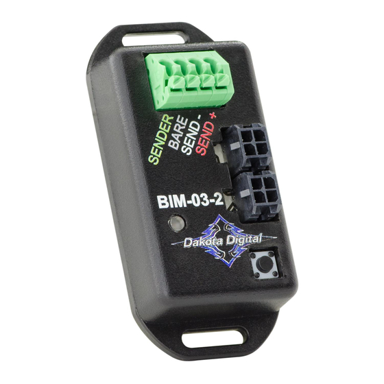
BIM-03-2
Bus Interface Module for pressure
(Sensor is sold separately)
Range
Resolution
0 - 300psi
0 - 100psi
0 - 300psi
30inHg - 80psi 0.2psi/1inHg.
0 - 2000psi
Low Warning
0 – 252
1
0 – 63
0.2
0 – 252
1
None
600 – 900
10
High Warning
48 – 300
9 – 99
48 – 300
7 – 69
900 – 1200
MAN#650503D
Advertisement
Table of Contents

Subscribe to Our Youtube Channel
Related Manuals for Dakota Digital BIM-03-2


Summary of Contents for Dakota Digital BIM-03-2
- Page 1 Either one can be connected to the gauge system or to another module, allowing several units to be daisy chained together. Do not connect the I/O port to anything other than a Dakota Digital gauge or BIM. Do not mount the module in the engine compartment;...
- Page 2 To set or change the ID number: The ID will not normally need to be changed. A green-red-red flash on the BIM-03-2 status light indicates an ID conflict with another connected BIM. The following procedure will allow the BIM-03-2 to automatically select a new, unused ID.
- Page 3 Vacuum/Boost setup. If a Vacuum/Boost sensor is connected to one of the channels, there is an additional step to correct for atmospheric pressure offsets due to elevation. After the BIM unit and sensor are connected and working, turn on the ignition key without starting the engine and wait for 30 seconds.
- Page 4 This Warranty does not apply to any product or part thereof which in the opinion of the Company has been damaged through alteration, improper installation, mishandling, misuse, neglect, or accident. Dakota Digital assumes no responsibility for loss of time, vehicle use, owner inconvenience nor related expenses.
Need help?
Do you have a question about the BIM-03-2 and is the answer not in the manual?
Questions and answers