Advertisement
Table of Contents
This guide is designed to get you up and running quickly with the minimal amount of options installed. It shows
a typical and abbreviated wiring diagram as well as how to set up your speedometer, tachometer, and fuel
sensor. A detailed description of all the wiring and connections can be found in the full instruction manual.
This control box has an odometer preset option that is only available one time within the first 100 miles
(160km) of operation. See "ODOMETER PRESET MENU" in main instruction manual for details.
Mount the display panel into your dash. (see mounting instructions or manual)
Install the supplied senders. (see sensor pack manual)
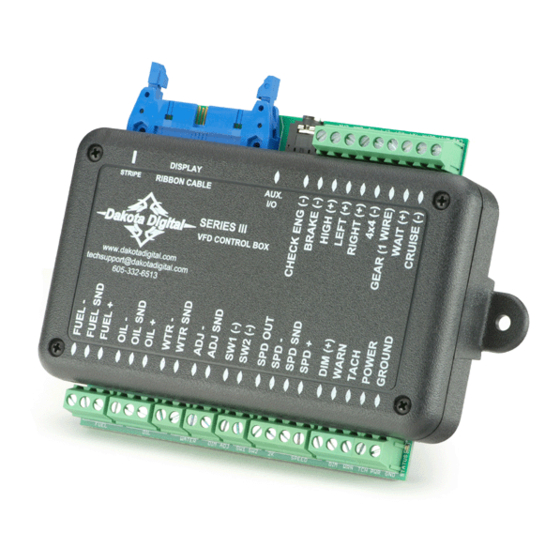
Mount and wire the control box. (see diagram on this sheet or see manual)
Setup the control box by selecting fuel sensor and programming speed.
RIBBON CABLE
Additional ground wire to fuel
sensor body or mounting screw.
EXSISTING
FUEL LEVEL
SENSOR
Set up the control box to match your vehicle.
cylinders and the fuel gauge must be set to match your fuel sender resistance curve or the instrument system will not
display correctly. The control box can read seven common fuel level sender resistance values. If your sender is not
listed, the system can be programmed to a custom sender (see full manual for details).
Sender type
GM 0-30 ohm
GM 0-90 ohm
GM 40-250 ohm (
GM 90-0 ohm
FORD 73-10 ohm (
FORD 20-150 ohm (
VDO 10-180 ohm
SW/SUN 33-240
User programmed
QUICK START GUIDE
DAKOTA DIGITAL VFD SERIES III GAUGE SYSTEM
***** IMPORTANT NOTE! *****
DISPLAY PANEL
DISPLAY
RIBBON CABLE
STRIPE
SERIES III
VFD CONTROL BOX
www.dakotadigital.com
techsupport@dakotadigital.com
605-332-6513
PRESSURE SENSOR
SEN-03-8
0-100 PSI
TEMP SENSOR
SEN-04-5
100-300 F
(mid 60's-earlier)
(mid 60's-late 90's)
late 90's-later)
(63-67 Corvette)
earlier -late 80's)
late 80's-later)
Quick Start Wiring Diagram
This drawing is a quick overview of the basic
wiring for your new Dakota Digital system. Once
completed all the basic functions should operate;
speed, tachometer, fuel level, voltmeter, water
temp, and oil pressure.
For further wiring assistance please read the
remainder of the manual. Each function is
described in detail along with some of the
auxiliary inputs that include turn signal indicators,
AUX.
I/O
high beam indicator, check engine, etc.
STATUS LED
Connect to main
chassis ground
ECU/ECM
Speed Output
SPEED SENSOR
SEN-01-5
16k PPM
The tachometer must be set to match the number of engine
Menu
Empty R
GM 30
0 ohms
GM 90
0 ohms
GM 250
40 ohms
63 VEt
90 ohms
F 10
73 ohms
F 150
20 ohms
V 180
10 ohms
SW
33
240 ohms
CUSTOM
User settable
+12V
KEY ON POWER
+12V KEY POWER
(fused 5 - 20 AMP max)
ECU/ECM
- +
or Ignition Box
(tach output)
Ignition Coil
(negative side)
Full R
30 ohms
90 ohms
249 ohms
0 ohms
10 ohms
150 ohms
180 ohms
33 ohms
User settable
MAN 650312 rev. E
Advertisement
Table of Contents

Related Manuals for Dakota Digital VFD III Series


Summary of Contents for Dakota Digital VFD III Series
- Page 1 Setup the control box by selecting fuel sensor and programming speed. Quick Start Wiring Diagram DISPLAY PANEL This drawing is a quick overview of the basic wiring for your new Dakota Digital system. Once completed all the basic functions should operate; speed, tachometer, fuel level, voltmeter, water RIBBON CABLE temp, and oil pressure.
- Page 2 Setup continued 1. Make sure you have at least switch 1(SW1) connected with one lead to ground and the other to the SW1 terminal on the control box. SW1 is used to enter setup. 2. Start with the ignition key off, hold SW1 while turning the key on. 3.
Need help?
Do you have a question about the VFD III Series and is the answer not in the manual?
Questions and answers