Table of Contents
Advertisement
IMPORTANT NOTE!
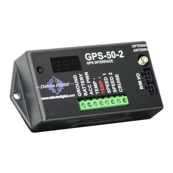
Connection for GPS
speed signal to other
electric speedometers.
setup/status switch
www.dakotadigital.com
605-332-6513
Connect to main
chassis ground
+12V
CONSTANT BATTERY POWER
(fused 5 - 20 AMP max)
+12V
KEY ON POWER
(fused 5 - 20 AMP max)
Standard speedometer output.
AC speedometer output.
Cruise control speed output.
Connect to
BIM-xx-2
power/data
harness
if needed
Connect to
GPS-50-2
This Bus Interface Module can be used to provide an accurate speedometer signal with most manufacturers' gauges and
also with a Dakota Digital system to provide speed, compass with air temp, clock, and altimeter functions. There are two
speedometer outputs to work with standard speedometers and a dedicated cruise control output. There are two interface
(I/O) ports on the module for use with a Dakota Digital gauge system. Either one can be connected to the gauge system
or to another module, allowing several units to be daisy chained together. Do not connect the I/O port to anything other
than a Dakota Digital gauge or BIM. Do not mount the module in the engine compartment; it should be mounted in interior
of the vehicle. Make sure the module is securely mounted and not hanging loose. It uses an internal acceleration
sensor which cannot accurately track the vehicle acceleration if it is loose.
The speed data does not use one of the 16 available bus ID's like other Dakota Digital BIM units do. Speed data is
transmitted and updated every 0.1 second. The remaining data is sent one at a time in sequence along with any other
BIM modules present on the system.
The optional SEN-15 outside air temperature sensor can be connected when a Dakota Digital gauge system is connected
to provide a combination compass & air temperature readings together.
The GPS speed signal can be momentarily incorrect due to interference from overpasses, tunnels, and nearby structures.
To avoid this problem, the system stabilizes the speedometer reading by constantly comparing it with an internal
acceleration sensor. When the key is off, the system goes into a very low power standby mode and only occasionally
wakes up to update GPS readings so that it is ready to start operating as soon as the key is turned on.
The GPS-50-2 has an internal GPS antenna to directly receive GPS signals without the need for an external antenna. An
external antenna can optionally be added to enhance reception if the GPS-50-2 is mounted where GPS signals cannot
reach it. Contact Dakota Digital for part number and availability.
GPS-50-2
GPS Speed and Bus Interface Module
When used to operate a cruise control, see the special
mounting requirements on the bottom of page 6.
OPTIONAL
GPS-50-2
ANTENNA
GPS INTERFACE
BIM-xx-1 adapter harness
BIM-xx-2 6 foot power/data harness
Connection to Dakota
Digital gauge system.
setup/status switch
www.dakotadigital.com
605-332-6513
+12V
CONSTANT BATTERY POWER
(fused 5 - 20 AMP max)
Accessory power and
ground provided by BIM
power/data harness.
+12V
RED WIRE
(fused 5 - 20 AMP max)
Connect to main
BLACK WIRE
chassis ground
1
Mount the outside
air temperature
sensor in the front
grill area or another
location that can get
good air flow while
the vehicle is being
driven.
OPTIONAL
GPS-50-2
ANTENNA
GPS INTERFACE
BIM-xx-2
Power
& data
connectors
optional speed and
cruise control outputs.
optional SEN-15
KEY ON POWER
To gauge control box
or BIM-xx-1
Connect directly to another BIM-xx-2
or to the BIM-xx-1 adapter harness
MAN #650519:B
Advertisement
Table of Contents

Related Manuals for Dakota Digital GPS-50-2


Summary of Contents for Dakota Digital GPS-50-2
- Page 1 The speed data does not use one of the 16 available bus ID’s like other Dakota Digital BIM units do. Speed data is transmitted and updated every 0.1 second. The remaining data is sent one at a time in sequence along with any other BIM modules present on the system.
- Page 2 Press and release SW1 until DONE is displayed. • Turn the key off. • Next, press and hold the switch on the GPS-50-2 while turning the key on. The GPS-50-2 display should show the current software revision. • Release the switch. The display should show “-C-”.
- Page 3 Press and release SW1 until DONE is displayed. • Turn the key off. • Next, press and hold the switch on the GPS-50-2 while turning the key on. The GPS-50-2 display should show the current software revision. • Release the switch. The display should show ì-C-”.
- Page 4 This can be repeated for additional channels, or the key can be turned off to exit setup. To set or change the Compass or Altimeter ID number: • Hold the switch beside the GPS-50-2 terminal strip while turning the key on. The display will show the current revision code while this is held. •...
- Page 5 60mph signal for testing. If you are going to be connecting a cruise control to the GPS-50-2, the CRUISE terminal provides an ECM style speed output signal. The output rate for this terminal is the same as for the SPEED terminals. It is not uncommon for the raw GPS speed data to vary by as much as 6 MPH when going under a large bridge or other structure.
- Page 6 While a transmission or wheel based speed signal is ideal for operating a cruise control, the GPS-50-2 can be used when this is not available. Special care must be taken in selecting the mounting location for the GPS-50-2 so that it can get a clear view of the satellites.
- Page 7 When the key is off the dot in the upper left corner will flash very slowly. If the switch on the GPS-50-2 is held, it will flash rapidly indicating that the key is off.
- Page 8 This Warranty is in lieu of all other expressed warranties or liabilities. Any implied warranties, including any implied warranty of merchantability, shall be limited to the duration of this written warranty. No person or representative is authorized to assume, for Dakota Digital, any liability other than expressed herein in connection with the sale of this product.
Need help?
Do you have a question about the GPS-50-2 and is the answer not in the manual?
Questions and answers