Advertisement
Quick Links
4 PIN AEM CAN
connector
Connect to the BIM-01-2
if you need to connect to a
BIM-xx-1 or gauge system
Connect to the BIM-01-2
if you need to connect to a
BIM-xx-2
This Bus Interface Module is designed to read engine information from specific AEM CAN bus (AEMnet) enabled devices.
These kits include Infinity ECU, Series 2 EMS or EMS-4. The module is connected to the AEM device through the 4-pin
AEMnet connection plug on the main harness.
There are two interface (I/O) ports on the module. Either one can be connected to the gauge system or to another
module, allowing several units to be daisy chained together. Do not connect the I/O port to anything other than a Dakota
Digital gauge or BIM. Do not mount the module in the engine compartment; it should be mounted in interior of the vehicle.
The engine and transmission information that is available from the unit depends on the AEM module programming and
add-ons. The possible values are: engine RPM, vehicle speed, engine coolant temperature, intake/manifold air
temperature, oil pressure, fuel pressure, A/F ratio, MIL, trans temp and boost.
Available readings: engine RPM, vehicle speed, engine coolant temperature, intake/manifold air temperature, oil
pressure, fuel pressure, A/F ratio, MIL, trans temp and boost.
Bus Interface Module for AEM Engine Management
AEM adapter harness
BIM-xx-1 adapter harness
BIM-xx-2 18 inch power/data harness
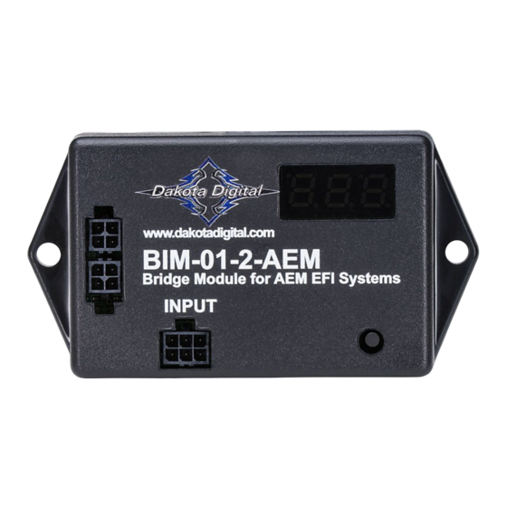
BIM-01-2-AEM
BIM-xx-2 power & data connectors.
Either one can be used.
www.dakotadigital.com
techsupport@dakotadigital.com
605-332-6513
BIM-01-2-AEM
Bridge Module for AEM Systems
INPUT
setup/status switch
Connect to the
BIM-01-2
+12V
KEY ON POWER
RED WIRE
(fused 5 - 20 AMP max)
Connect to main
BLACK WIRE
chassis ground
To gauge control box
or BIM-xx-1
Connect directly to
another BIM-xx-2
MAN #650617
Advertisement

Related Manuals for Dakota Digital BIM-01-2-AEM


Summary of Contents for Dakota Digital BIM-01-2-AEM
- Page 1 BIM-01-2-AEM Bus Interface Module for AEM Engine Management BIM-xx-2 power & data connectors. Either one can be used. www.dakotadigital.com techsupport@dakotadigital.com 605-332-6513 BIM-01-2-AEM Bridge Module for AEM Systems INPUT setup/status switch AEM adapter harness 4 PIN AEM CAN connector Connect to the...
- Page 2 System Setup: AEM system setup This unit is plug-and-play. Attach the included Y-harness to your AEMnet device. No further setup is required. AEM boost reading This module is programmed to monitor boost(PSI). This is done by monitoring the MAP sensor. To ensure accuracy we calibrate the baseline barometric pressure from the MAP sensor when the device receives power and the engine is off.
- Page 3 HDX setup (Can also be completed using the Bluetooth app): Using speed from the BIM-01-2 • With ignition on. Press and hold both switches to enter SETUP. • Press and release either switch until SPEED is selected. Press and hold either switch to enter SPEED menu. •...
- Page 4 This Warranty is in lieu of all other expressed warranties or liabilities. Any implied warranties, including any implied warranty of merchantability, shall be limited to the duration of this written warranty. No person or representative is authorized to assume, for Dakota Digital, any liability other than expressed herein in connection with the sale of this product.
Need help?
Do you have a question about the BIM-01-2-AEM and is the answer not in the manual?
Questions and answers