Advertisement
Connect to main
chassis ground
+12V
KEY ON POWER
(fused 5 - 20 AMP max)
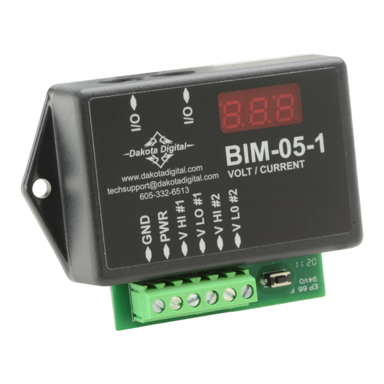
This Bus Interface Module has inputs for up to two devices to be monitored. Each channel can be configured
individually. There are two interface (I/O) ports on the module. Either one can be connected to the gauge system or to
another module, allowing several units to be daisy chained together. Do not connect the I/O port to anything other
than a Dakota Digital gauge or BIM. Do not mount the module in the engine compartment; it should be mounted in
interior of the vehicle.
Each sensor connected to the bus needs a unique ID number assigned to it. This module has inputs for two channels
so it can use one or two ID numbers. Each of the two channels can be assigned an ID from 1 – 16, or turned off. The
factory default ID numbers are 3 and 4 for the two inputs respectively. The factory default labels are VOLTS for both.
Labels available for each input are:
VOLT -
voltage input. This will display VOLT, V, or BIM VOLTAGE.
CURRENT -
SEN-20-3 sensor input. This will display AMPS, C, or CURRENT.
Specs for each input are:
Part #
VOLT
none
VOLT
none
CURRENT
SEN-20-3
Bus Interface Module for voltage and current
(Current sensors are sold separately)
To gauge control box
or another BIM
BIM-05-1
www.dakotadigital.com
techsupport@dakotadigital.com
VOLT / CURRENT
605-332-6513
* Connect V HI or V LO, but not both.
Input
Range
V HI
0 – 50.0 V
V LO
0 – 5.00 V
V LO
0 – 250 A
BIM-05-1
Optional
SEN-20-3
for current
monitoring
(purchased separately)
Connect to BIM-05
GND terminal
+12V
KEY ON POWER
(fused 5 - 20 AMP max)
setup/status switch
Device monitored by Channel 2
Device monitored by Channel 1
resolution
low warning
0.1
0 – 31
0.01
0 – 3.1
1
none
SEN-20-3
www.dakotadigital.com
605-332-6513
Connect to BIM-05 V LO input
high warning
10 – 41
1.9 – 5.0
5 – 320
MAN #650343b
Advertisement
Table of Contents

Subscribe to Our Youtube Channel
Related Manuals for Dakota Digital BIM-05-1


Summary of Contents for Dakota Digital BIM-05-1
- Page 1 Do not connect the I/O port to anything other than a Dakota Digital gauge or BIM. Do not mount the module in the engine compartment; it should be mounted in interior of the vehicle.
- Page 2 To set or change the ID numbers: • Hold the switch beside the BIM terminal strip while turning the key on. The BIM display will show the current revision code while this is held. • Release the switch. The display will show ì-C-”. •...
- Page 3 When you are finished, select BACK to return to the BIM list menu, select BACK to return to the main menu, and then select EXIT SETUP to return to normal operation. With HDX systems the setup can also be done with the Dakota Digital app for Apple and Android devices. Troubleshooting quick tips: While the BIM is operating, the dot in the upper left corner of the display will indicate the status.
- Page 4 Dakota Digital’s option. This warranty does not cover nor extend to damage to the vehicle’s systems, and does not cover diagnosis, removal or reinstallation of the product.
Need help?
Do you have a question about the BIM-05-1 and is the answer not in the manual?
Questions and answers