Advertisement
setup/status switch
Connect to main
chassis ground
+12V
KEY ON POWER
(fused 5 - 20 AMP max)
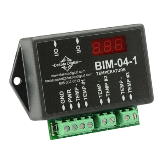
This Bus Interface Module has inputs for up to three temperature sensors, Dakota Digital part number SEN-04-5.
Each input can be configured individually. There are two interface (I/O) ports on the module. Either one can be
connected to the gauge system or to another module, allowing several units to be daisy chained together. Do not
connect the I/O port to anything other than a Dakota Digital gauge or BIM. Do not mount the module in the engine
compartment; it should be mounted in interior of the vehicle.
Each sensor connected to the bus needs a unique ID number assigned to it. This module has three inputs so it can
use one, two, or three ID numbers. Each of the three inputs can be assigned an ID from 1 – 16, or turned off. The
factory default ID numbers are 1, 2, and OFF for the three inputs respectively. The factory default labels are TEMP for
all inputs.
Labels available for each input are:
TEMP -
generic temperature input. This will display TEMP x, Tx, or TEMPERATURE CHx where x is a
number from 1 – 8 corresponding to the module ID number. ID's over 8 will start over at 1.
WATER -
dual water temperature input for right hand side water temp sensor. When this is active the gauge
system water display will show the higher of the left and right sensors. The message display will show
both temperature readings side by side. The gauge system water temp sensor should be installed in
the left hand side.
OIL -
oil temperature input. This will display OIL, OT, or OIL TEMP.
TRANS -
transmission temperature input. This will display TRANS, TT, or TRANS TEMP.
DIFF -
rear differential temperature input. This will display DIFF, DT, or DIFF TEMP.
Specs for each input are:
Sensor
TEMP
SEN-04-5 only 100 - 320F
WATER
SEN-04-5 only 100 - 320F
OIL
SEN-04-5 only 100 - 320F
TRANS
SEN-04-5 only 100 - 320F
DIFF
SEN-04-5 only 100 - 320F
Temperature unit will follow the unit set for the main water temp gauge, Fahrenheit or Celsius.
The sensor has 1/8" NPT threads. Adapters are available to convert to other thread sizes.
Bus Interface Module for fluid temperature
(Sensors are sold separately)
To gauge control box
or another BIM
BIM-04-1
www.dakotadigital.com
techsupport@dakotadigital.com
TEMPERATURE
605-332-6513
Range
high warning
131 – 320
none (set by gauge system water temp)
131 – 320
131 – 320
131 – 320
BIM-04
Channel 3 temperature sensor
Channel 2 temperature sensor
Channel 1 temperature sensor
MAN#650327:A
Advertisement
Table of Contents

Subscribe to Our Youtube Channel
Related Manuals for Dakota Digital BIM-04


Summary of Contents for Dakota Digital BIM-04
- Page 1 Do not connect the I/O port to anything other than a Dakota Digital gauge or BIM. Do not mount the module in the engine compartment;...
- Page 2 To set or change the ID numbers: • Hold the switch beside the BIM terminal strip while turning the key on. The BIM display will show the current revision code while this is held. • Release the switch. The display will show “-C-”. •...
- Page 3 Troubleshooting quick tips: While the BIM is operating, the dot in the upper left corner of the display will indicate the status. On steady indicates it is powered up but not receiving any bus activity. Flashing indicates it is communicating on the bus. To see the sensor and channel status on the BIM display, press and hold the switch.
- Page 4 Dakota Digital’s option. This warranty does not cover nor extend to damage to the vehicle’s systems, and does not cover removal or reinstallation of the product.
Need help?
Do you have a question about the BIM-04 and is the answer not in the manual?
Questions and answers