Table of Contents
Advertisement
Quick Links
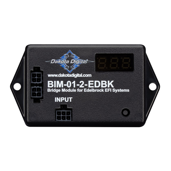
Bus Interface Module for Edelbrock Engine Management
4 PIN CAN
connector
Connect to the BIM-01-2
if you need to connect to a
BIM-xx-2
This Bus Interface Module is designed to read engine information from specific Edelbrock CAN bus enabled EFI units
which currently includes: Pro-Flo 4 EFI system with v53 or later. The module is connected to the Edelbrock device main
harness through one of the adapter harnesses that are included within this kit.
There are two interface (I/O) ports on the module. Either one can be connected to the gauge system or to another
module, allowing several units to be daisy chained together. Do not connect the I/O port to anything other than a Dakota
Digital gauge or BIM. Do not mount the module in the engine compartment; it should be mounted in interior of the vehicle.
The engine and transmission information that is available from the unit depends on the Edelbrock module programming
and add-ons. The possible values are: engine RPM, engine coolant temperature, intake/manifold air temperature, fuel
pressure, A/F ratio, MAP and boost.
Available readings: engine RPM, engine coolant temperature, intake/manifold air temperature, fuel pressure, A/F
ratio, MAP and boost.
BIM-01-2-EDBK
BIM-xx-2 power & data connectors.
Either one can be used.
www.dakotadigital.com
techsupport@dakotadigital.com
605-332-6513
BIM-01-2-EDBK
Bridge Module for Edelbrock Systems
INPUT
Adapter harness
BIM-xx-2 18 inch power/data harness
setup/status switch
Connect to the
BIM-01-2
Connect directly to
another BIM-xx-2
MAN #650687D
Advertisement
Table of Contents

Subscribe to Our Youtube Channel
Related Manuals for Dakota Digital BIM-01-2-EDBK


Summary of Contents for Dakota Digital BIM-01-2-EDBK
- Page 1 BIM-01-2-EDBK Bus Interface Module for Edelbrock Engine Management BIM-xx-2 power & data connectors. Either one can be used. www.dakotadigital.com techsupport@dakotadigital.com 605-332-6513 BIM-01-2-EDBK Bridge Module for Edelbrock Systems INPUT setup/status switch 4 PIN CAN connector Adapter harness Connect to the BIM-01-2...
- Page 2 System Setup: Edelbrock system setup This unit is plug-and-play. Attach the included DB9-harness to your Edelbrock EFI system. No further setup is required. Edelbrock MAP reading By default, this module is programmed to monitor MAP(PSI). The MAP reading will show up on your gauge system with the label ‘boost’...
- Page 3 SERVICE AND REPAIR DAKOTA DIGITAL offers complete service and repair of its product line. In addition, technical consultation is available to help you work through any questions or problems you may be having installing one of our products. Please read through the Troubleshooting Guide. There, you will find the solution to most problems.
- Page 4 This Warranty is in lieu of all other expressed warranties or liabilities. Any implied warranties, including any implied warranty of merchantability, shall be limited to the duration of this written warranty. No person or representative is authorized to assume, for Dakota Digital, any liability other than expressed herein in connection with the sale of this product.
Need help?
Do you have a question about the BIM-01-2-EDBK and is the answer not in the manual?
Questions and answers