Table of Contents
Advertisement
Quick Links
INSTALLATION AND OPERATOR'S MANUAL
Digital Climate Control for Vintage Air GEN-IV systems
DCC control box (x1)
HLC harness (x1)
Grommet temp sensors (x4)
2 ½" Vent sensor housings (x2)
FOR
DCC-4000
PARTS INCLUDED WITH THIS SYSTEM
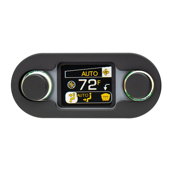
DCC-4000 display (x1)
DCC display
harness (x1)
11" plastic ties (x6)
2" Vent sensor
housings (x2)
1
Mount brackets (x2)
DCC controller
Clip temp sensors (x2)
harness (x1)
6 " plastic ties (x2)
Installation / operator's
manual (x1)
Cutout template (x1)
Thumb nuts (x2)
MAN # 650702
Advertisement
Table of Contents

Related Manuals for Dakota Digital DCC-4000


Summary of Contents for Dakota Digital DCC-4000
- Page 1 DCC-4000 Digital Climate Control for Vintage Air GEN-IV systems PARTS INCLUDED WITH THIS SYSTEM Mount brackets (x2) Thumb nuts (x2) DCC control box (x1) DCC-4000 display (x1) HLC harness (x1) DCC controller DCC display Clip temp sensors (x2) harness (x1) harness (x1) 6 “...
-
Page 2: Connection Diagram
(optional*) Using the HLC harness (2 six pin connectors) connect to either one of the 6 pin connectors on the DCC-4000 display. Connect the other end to the “CLOCK CABLE” port on HDX or RTX control box. (optional*) If the HDX / RTX system has an analog clock, connect its HLC harness to the remaining 6 pin connector on the back of the DCC-4000 display. -
Page 3: Feature Diagram
FEATURE DIAGRAM: 1. Temperature knob Turn to adjust temperature Press to toggle between AC and Econ DCC CONTROL BOX FOR GEN-IV 2. AC / ECON indicator Shows snowflake for AC, and a - CABIN + CABIN snowflake in backslash-circle for Econ - DEFROST + DEFROST - FLOOR B... - Page 4 Using the 3/8” drill bit with the proper rubber or wood stop installed, drill a hole in the defrost duct in the location shown. Insert one of the four supplied grommet type temperature sensors into the drilled hole with the wires pointing to the outside of the duct housing.
- Page 5 STEP 4: INSTALL THE GEN-IV MODULE Install the GEN-IV module if it has not yet been installed in the vehicle. Refer to the installation manual for the GEN-IV module for detailed instructions for your application. STEP 5: INSTALL THE VENT SENSORS The vent temperature sensors are mounted in the flexible duct tubing from the GEN-IV module.
-
Page 6: Operation
OPERATION: BLOWER KNOB (knob on right side for horizontal, or bottom side for vertical): The blower knob handles two adjustments which can be selected by pressing the knob. Each press and release of the knob will toggle adjustment modes on the display as indicated below. For horizontal display modes, an arrow indicator points to the selected adjustment. - Page 7 NIGHT TIME DIMMING AND THEMES: The DCC-4000 has two color / brightness themes that can each be setup by the user, a day time theme and a night time theme. The night time theme will be displayed when the dim circuit in the stock GEN-IV harness is powered (when headlights are on).
- Page 8 SETUP: To enter the setup menu, press and hold either of adjustment knobs while turning the key ON (do not start engine). The screen will display “SETUP.” Release the knob and the system will enter the setup menu. To scroll through the options in the setup menu, turn either knob. The currently active option will be highlighted.
- Page 9 Any action for breach of any warranty hereunder, including any implied warranty of merchantability, must be brought within a period of 24 months from date of original purchase. No person or representative is authorized to assume, for Dakota Digital, any liability other than expressed herein in connection with the sale of this product.
-
Page 10: Troubleshooting
WARNING: This product can expose you to chemicals including lead, which is known to the State of California to cause cancer and birth defects or other reproductive harm. For more information go to www.P65Warnings.ca.gov Copyright 2019 – Dakota Digital, Inc. MAN # 650702...
Need help?
Do you have a question about the DCC-4000 and is the answer not in the manual?
Questions and answers