
Related Manuals for Advantech RSB-3730


Summary of Contents for Advantech RSB-3730
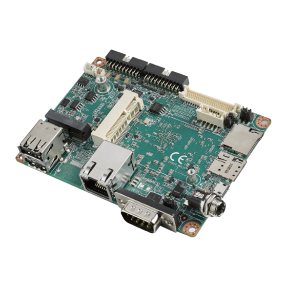
- Page 1 User Manual RSB-3730 ® NXP iMX8M Mini ARM ® Cortex -A53 2.5″ SBC with UIO40 Express...
- Page 2 No part of this manual may be reproduced, copied, translated, or transmitted in any form or by any means without the prior written permission of Advantech Co., Ltd. The information provided in this manual is intended to be accurate and reliable.
- Page 3 Packing List Before system installation, check that the items listed below are included and in good condition. If any item does not accord with the list, contact your dealer immediately. 1 x RSB-3730 SBC with heatsink Ordering Information Part No.
- Page 4 – The equipment shows obvious signs of breakage. DISCLAIMER: These instructions are provided according to IEC 704-1 standards. Advantech disclaims all responsibility for the accuracy of any statements contained herein. Safety Precautions - Static Electricity Follow these simple precautions to protect yourself from harm and the products from damage.
-
Page 5: Table Of Contents
Figure 2.11 NANO SIM Card Slot..........21 Table 2.19:Micro USB Connector (OTG)........21 Figure 2.12 Micro USB Connector..........21 Table 2.20:DC Power Jack (DCIN1)........... 22 Figure 2.13 DC Jack ..............22 Table 2.21:RS232 & R485 (COM)..........22 RSB-3730 User Manual... - Page 6 GPIO ....................... 31 Table 3.1: GPIO ................ 31 UART ...................... 32 3.4.1 RSB-3730 UART ................ 32 Table 3.2: RSB-3730 UART ............32 3.4.2 How to Configure RS232 or RS485 Mode........32 Audio....................... 33 I2c Test ....................34 SD/MMC Card/USB/SpiFlash ..............34 3.7.1...
-
Page 7: Chapter 1 General
Chapter General... -
Page 8: Introduction
Introduction RSB-3730 is a RISC 2.5" single board computer (SBC) powered by an NXP i.MX8M Mini Cortex-A53 Quad high-performance processor. It offers a single display via HDMI/LVDS/DSI and plenty of I/O with 1 x GbE, 3 x serial, 5 x USB, 11 x GPIO. RSB- 3730 also features Mini-PCIe for LTE and M.2 for Wi-Fi/BT. -
Page 9: Mechanical Specifications
Environmental Specifications Operating temperature: 0 ~ 60°C / -40 ~ 85°C Operating humidity: 5 ~ 95% relative humidity, non-condensing Storage temperature: -40 ~ 85°C (-40 ~ 185°F) Storage humidity: 60°C @ 95% RH non-condensing RSB-3730 User Manual... -
Page 10: Block Diagram
Mini PCIE SD slot USB HUB 1- 7 USB OTG 2 SIM slot debug Transceiver A53 debug UART2 2 x USB Type-A RS232/485 Transceiver UART4 MSP430 PCIe 2.0 GPIOx8 UART3 Transceiver UIO Type-B UIO Type-A UART1 Transceiver GPIOx4 RSB-3730 User Manual... -
Page 11: Chapter 2 H/W Installation
Chapter H/W Installation This chapter gives mechanical and connector information on the RSB-3730. -
Page 12: Jumper And Connector Locations
Jumper and Connector Locations The following sections show the external connectors and pin assignments for appli- cations. RSB-3730 User Manual... -
Page 13: Board Dimensions
Board Dimensions Figure 2.1 Board Dimensions RSB-3730 User Manual... -
Page 14: Jumpers
2.3.2 Jumper List Table 2.1: Jumper List VDD 3.3V & 5V LVDS VDD & Backlight power level select BLP1 LVDS Backlight power 12V select AT & ATX Mode select and boot mode select Power Button RSB-3730 User Manual... -
Page 15: Jumper Settings
LVDS Backlight POWER 5V (4-6) LVDS Backlight POWER 3.3V Table 2.3: BLP1 BLP1 LVDS BKLT PWR 12V level select Part number 1653002101-02 Footprint HD_2x1P_79_D Description PIN HEADER 2x1P 2.0mm 180D(M) DIP 21N12050 Setting Function (1-2) LVDS Backlight POWER 12V RSB-3730 User Manual... - Page 16 Table 2.5: BTN Power Button & Watchdog AT & ATX Mode Part number 1653003260 Footprint HD_3x2P_79 Description PIN HEADER 3x2P 2.0mm 180D(M) SMD 21N22050 Setting Function (1-2) For power button cable connection when SW1 selects ATX Mode RSB-3730 User Manual...
-
Page 17: Connectors
Connector Pin Definitions 2.4.2.1 RS232/Debug Port (COM1/DEBUG2) RSB-3730 can communicate with a host server (Windows or Linux) by using a debug cable (Advantech number: 1700021565-11). If you need a boot select out box, you can use the appropriate cable (Advantech number: 1700034046-01). - Page 18 Description +COIN_RTC Figure 2.3 DC RTC Battery Connector 2.4.2.3 M.2 (M2) RSB-3730 supports the socket1 connectivity type 2230 S1&S2&S3 E-Key M.2 inter- face. The detailed pin definitions are as shown below. Table 2.9: M.2 (M2) Signal Name Signal Name +V3.3_M2 USB_M2_D+ +V3.3_M2...
- Page 19 Table 2.9: M.2 (M2) PCIE_B_REFCK_P PCIE_B_REFCK_N M2_SYSCLK_3V3 PERST# PCIE_CLKREQ# NGFF_BT_DISABLE# +3.3V PU to 10Kohm NGFF_WIFI_DISABLE# BT_WAKE_HOST +V3.3_M2 +V3.3_M2 Figure 2.4 M.2 CONN RSB-3730 User Manual...
- Page 20 The MIC connector pin definitions are as shown below. Table 2.11: MIC Connector Description MIC_IN AGND Figure 2.6 MIC Connector 2.4.2.5 RSB-3730 supports UIO-40 express UIO. The pin definitions are as shown below: Table 2.12: UIO1 Signal Name Signal Name +V5_USB1 USB1_D- USB2_D+...
- Page 21 GPIO9 from I2C to GPIO chipset GPIO10 (from CPU) TCA9538PWR GPIO11 from CPU or I2C to GPIO GPIO12 from CPU or I2C to GPIO chipset chipset TCA9538PWR by SW setting TCA9538PWR by SW setting I2C4_SDA_CONN I2C4_SCL_CONN +V3.3_OUT RSB-3730 User Manual...
- Page 22 2.4.2.6 LVDS Connector (LVDS) RSB-3730 provides an LVDS 20x2-pin board-to-board connector for one-port single- channel 24-bit LVDS or one-port dual-channel 24-bit LVDS, or four-lane MIPI DSI according to the BOM option. Table 2.14: LVDS Connector (LVDS) Signal Name Signal Name...
- Page 23 LVDS panel (refer to the jumper settings for BL and LCD on the datasheet that you will use). Table 2.15: LVDS Inverter Power Connector (BL) Description LCD0_BKLT_PWM LCD0_BKLT_EN +VDD_BKLT Figure 2.8 LVDS Inverter Power Connector RSB-3730 User Manual...
- Page 24 2.4.2.8 Micro SD Slot (SD) RSB-3730 supports an SD/MMC card, with supported capacity up to 64GB. You can use a SanDisk U1 C10 A1 TF, Kingston U1 A1 V10 switch, SAMSUNG U1 C10 EVO TF card, or Transcend Class4 Micro SDHC card.
- Page 25 2.4.2.9 Mini PCIe (MPCIE) RSB-3730 supports the Mini PCIe interface. The detailed pin definitions are as shown below. Table 2.17: Mini PCIe (MPCIE) Signal Name Signal Name +V3.3_MINICARD MINICARD_DET#_3V3 UIM_VCC UIM_DATA UIM_CLK UIM_RESET W_DISABLE# MINICARD_RESET#_3V3 MINICARD- MINICARD+ +V3.3_MINICARD +V3.3_MINICARD +V3.3_MINICARD...
- Page 26 Figure 2.10 Mini PCIe Connector RSB-3730 User Manual...
- Page 27 2.4.2.10 NANO SIM Card Slot (SIM) RSB-3730 supports an on-board NANO SIM socket for 4G integration. Please insert a valid SIM card to connect to a 4G network. Table 2.18: NANO SIM Card Slot (SIM) Description UIM_PWR UIM_RESET UIM_CLK UIM_DATA Figure 2.11 NANO SIM Card Slot...
- Page 28 Table 2.20: DC Power Jack (DCIN1) Description +12V Figure 2.13 DC Jack 2.4.2.13 RS232 & R485 (COM) RSB-3730 has one RS232 & RS485 DB9 com port. You can select RS232 or RS485 by setenv on uboot. Table 2.21: RS232 & R485 (COM) Description COM_DCD COM_RXD...
- Page 29 2.4.2.14 Ethernet Connector (LAN1) RSB-3730 provides one RJ-45 LAN interface connector, which is compliant with 1000 base-T IEEE 802.3ab, 100 base-TX IEEE 802.3u, and 10 base-T IEEE 802.3.The Ethernet ports provide a standard RJ-45 jack connection with LED indica- tors on the front side to show Active/Link and speed status.
- Page 30 2.4.2.15 HDMI Connector (HDMI) RSB-3730 supports one HDMI port. The HDMI pins are defined as shown below. Table 2.23: HDMI Connector (HDMI) Description Description HDMI_TX2+_C HDMI1_z_CLK- HDMI_TX2-_C HDMI_TX1+_C HDMI_DDC_SCL HDMI_TX1-_C HDMI_DDC_SDA HDMI_TX0+_C +5V_HDMI HDMI_TX0-_C HDMI1_HPD HDMI_CLK+_C Figure 2.16 HDMI Connector...
- Page 31 2.4.2.16 USB Type-A Connector (USB1) RSB-3730 supports two standard USB 2.0 Type-A connectors on the coastline. Table 2.24: USB Type-A Connector (USB1) Description +V5_USB4 USB_z_P4_DM USB_z_P4_DP +V5_USB5 USB_z_P5_DM USB_z_P5_DP Figure 2.17 USB Port Connector 2.4.2.17 Reset Button (RST) RSB-3730 supports a reset button on the coastline.
-
Page 32: Quick Start
Figure 2.19 LED Quick Start 2.5.1 Debug Port Connection Connect the debug cable to the RSB-3730 debug port. Connect the other end of the debug cable to the USB-to-RS-232 cable. Then connect that cable to your PC. Table 2.27: Debug Port Connection... -
Page 33: Debug Port Settings
Figure 2-7. After the bootloader is programmed on the SD card, connect the power adapter connector to the DC jack on RSB-3730 to power up the board. The bootloader prompt will be displayed on the terminal screen. Figure 2.20 HyperTerminal Settings for Terminal Setup ... - Page 34 RSB-3730 User Manual...
-
Page 35: Software Functionality
Chapter Software Functionality This chapter details the software programs on the RSB-3730 plat- form. -
Page 36: Introduction
The purpose of this chapter is to introduce the software development capabilities of RSB-3730, so that you can develop your own application(s) efficiently. RSB-3730 is designed to support a Linux host only, so you may not be able to develop your application on a Windows/Android host PC. For now, the official sup- ported host Linux version is Ubuntu 18.04 LTS 64-bit;... -
Page 37: Gpio
The node numbers of the exported GPIO are consistent with the export order, increasing from 1. Export GPIO1 # echo 150> /sys/class/gpio/export Set GPIO direction to in/out # echo "out" > /sys/class/gpio/gpio1/direction Set GPIO value 0/1 if GPIO pin definition as output # echo 1 > /sys/class/gpio/gpio1/value RSB-3730 User Manual... -
Page 38: Uart
Therefore, the system needs to control the RS- 485 transceiver's transmit mode. Usually the UART RTS signal is used to switch the transmitter on and off. 3.4.1 RSB-3730 UART Table 3.2: RSB-3730 UART COM Name Device Node Remark UIO2 com1... -
Page 39: Audio
Front Right: Playback 31 [100%] [0.00dB] # amixer set PCM 100% Simple mixer control 'PCM',0 Capabilities: pvolume Playback channels: Front Left - Front Right Limits: Playback 0 - 192 Mono: Front Left: Playback 192 [100%] Front Right: Playback 192 [100%] RSB-3730 User Manual... -
Page 40: I2C Test
# dd if=/dev/urandom of=data bs=1 count=1024 # dd if=/dev/mmcblk1 of=backup bs=1 count=1024 skip=4096 # dd if=data of=/dev/mmcblk1 bs=1 seek=4096 # dd if=/dev/mmcblk1 of=data1 bs=1 count=1024 skip=4096 # diff data data1 # dd if=backup of=/dev/mmcblk1 bs=1 seek=4096 3.7.2 USB Disk Test RSB-3730 User Manual... -
Page 41: Rtc
---- Running < /unit_tests/Watchdog/wdt_driver_test.out > test ---- Starting wdt_driver (timeout: 1, sleep: 2, test: ioctl) Trying to set time out value=1 seconds The actual timeout was set to 1 seconds Now reading back -- The timeout is 1 seconds RSB-3730 User Manual... -
Page 42: Hdmi
=> setenv fdt_file imx8mm-rsb3730-a2-dsi2lvds-800x480.dtb => saveenv => boot Set the resolution to 1920x1080 (Ex: G215HV01 panel). => setenv fdt_file imx8mm-rsb3730-a2-dsi2lvds-1920x1080.dtb => saveenv => boot 3.11.2 MIPI DSI Panel: G101UAN02.0 => setenv fdt_file imx8mm-rsb3730-a2-dsi-auog101uan02.dtb => saveenv => boot RSB-3730 User Manual... -
Page 43: Tpm
3.12 Check the i2c device( tpm : 1----0x2e) # i2cdetect -r -y 1 I2c set and get. # i2cset -f -y 1 0x2e 0x00 0x3f # i2cget -f -y 1 0x2e 0x00 0x3f RSB-3730 User Manual... - Page 44 RSB-3730 User Manual...
-
Page 45: Network Setup
Chapter Network Setup... -
Page 46: Wi-Fi Setup
Wait for the IP address to appear. Test the network. # ping -I wwan0 8.8.8.8 PING 8.8.8.8 (8.8.8.8) 56(84) bytes of data. 64 bytes from 8.8.8.8: icmp_seq=1 ttl=54 time=2.10 ms 64 bytes from 8.8.8.8: icmp_seq=2 ttl=54 time=2.10 ms RSB-3730 User Manual... -
Page 47: Ethernet
Ethernet RSB-3730 supports two Ethernet connections (eth0 and eth1). When there is access to the second network module eth1. RSB-3730 User Manual... -
Page 48: Installing The System From An Sd Card
Insert the USB disk and SD card, then boot the whole system from the SD card by changing SW1 to 1-2 ON. Enter the usb disk folder, and make a bootable emmc. # cd /run/media/sda1/ # umount /dev/mmcblk2* # dd if=./imx-image-full-imx8mmrsb3730a2-xxxx.rootfs.sdcard \ of=/dev/mmcblk2 bs=1M # sync RSB-3730 User Manual... -
Page 49: Advantech Services
Chapter Advantech Services This chapter introduces the Advantech Design-In service, technical support, and warranty policy for the RSB-3730 evalua- tion kit. -
Page 50: Risc Design-In Services
Design Assistance Service Advantech provides a checklist for engineers to easily check their schematics and also review them based on customer carrier board schematics. These services are preventative, and help catch design errors before they occur. It helps to save a lot of time and cost with regard to developing carrier boards. - Page 51 Advantech has been involved in the industrial computer industry for many years and has found that customers usually have the following concerns when implementing modular designs.
- Page 52 By virtue of a close interactive relationship with leading original manufacturers of CPUs and chipsets, such as ARM, TI, and Freescale, Advantech helps solve com- munication and technical support difficulties, and that can reduce the uncertainties of product development, too. Advantech’s professional software team also focuses on providing a complete Board Support Package and assists customers to build up a software development environment for their RISC platforms.
- Page 53 Therefore, the customer has to learn from trial and error and to finally arrive at the best solution with the least effort. Advantech’s team has years of experience in customer support and HW/SW development. Consequently, we can support customers with professional advice and information as well as short- ening development time and enabling more effective product integration.
-
Page 54: Contact Information
Contact Information Below is the contact information for Advantech customer service. Region/Country Contact Information 1-888-576-9688 Brazil 0800-770-5355 Mexico 01-800-467-2415 Europe (toll-free) 00800-2426-8080 Singapore & SAP 65-64421000 Malaysia 1800-88-1809 Australia (toll-free) 1300-308-531 800-810-0345 China (toll-free) 800-810-8389 sales@advantech.com.cn India (toll-free) 1-800-425-5071 Japan (toll-free) -
Page 55: Global Service Policy
(dead on arrival). The DOA cross-shipment excludes any shipping damage, custom- ized, and/or build-to-order products. For those products which are not DOA, the return fee to an authorized ADVANTECH repair facility will be at the customer’s expense. The shipping fees for reconstructed products from ADVANTECH back to customers' sites will be at ADVANTECH's expense. -
Page 56: Repair Process
"Problem Description" section. Vague entries such as "does not work" and "failure" are not acceptable. If you are uncertain about the cause of the problem, please contact ADVANTECH's Application Engineers (AE). They may be able to find a solution that does not require sending the product in for repair. - Page 57 without warranty. If a product has been repaired by ADVANTECH, and within three months after such a repair, the product requires another repair for the same problem, ADVANTECH will perform this repair free of charge. However, such free repairs do not apply to prod- ucts which have been misused, abused, or subjected to unauthorized disassembly/ modification;...
- Page 58 5.3.2.6 Shipping Back to the Customer The forwarding company for RMA returns from ADVANTECH to customers is selected by ADVANTECH. Per customer requirement, other express services can be adopted, such as UPS, FedEx, etc. The customer must bear the extra costs of such alternative shipments.
- Page 59 RSB-3730 User Manual...
- Page 60 No part of this publication may be reproduced in any form or by any means, such as electronically, by photocopying, recording, or otherwise, without prior written permission from the publisher. All brand and product names are trademarks or registered trademarks of their respective companies. © Advantech Co., Ltd. 2023...
Need help?
Do you have a question about the RSB-3730 and is the answer not in the manual?
Questions and answers