
Related Manuals for Advantech RSB-4810


Summary of Contents for Advantech RSB-4810
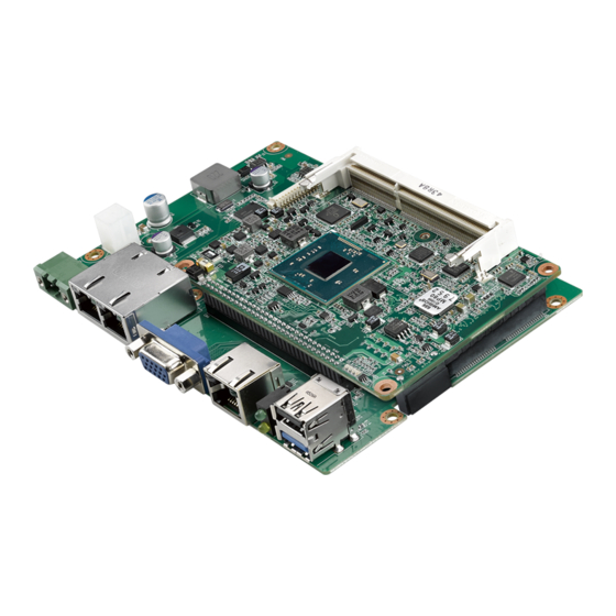
- Page 1 User Manual RSB-4810 3.5” Single-board Computer with ® ® Rockchip Arm Cortex -A55 Processor...
- Page 2 No part of this manual may be reproduced, copied, translated, or transmitted in any form or by any means without the prior written permission of Advantech Co., Ltd. The information provided in this manual is intended to be accurate and reliable.
- Page 3 Packing List Before installation, ensure that the following items have been shipped: 1 x RSB-4810 SBC Safety Precautions – Static Electricity Follow this simple precaution to protect yourself from harm and the products from...
- Page 4 Advantech disclaims all responsibility for the accuracy of any statements contained herein. Ordering Information Part Number Description RSB-4810, RK3568, 2GB DDR 16GB eMMC, 0 ~ 60 °C/32 ~ 140 RSB-4810CQ-MNA1E °F RSB-4810, RK3568J, 2GB DDR 16GB eMMC, -40 ~ 85 °C/-40 ~ RSB-4810WQ-MNA1E 185 °F...
- Page 5 Antenna 4G/LTE full band L=11 cm 50 Ohm SQF-ISDM1-16G-21C SQ Flash SD card UHS-I MLC 16GB (0 ~ 70 °C; 32 ~ 158 °F) 1700023588-01 M Cable USB-A 4P(M)/USB-A 4P(M) 120 cm *Contact Advantech to obtain a suitable cellular module for your region. RSB-4810 User Manual...
- Page 6 RSB-4810 User Manual...
-
Page 7: Table Of Contents
Figure 2.23Reset Button............. 33 Figure 2.24GPIO Pin Header............34 Figure 2.25SPI Pin Header............34 Figure 2.26I2C Connector ............35 LED ......................35 Quick Start Guide..................36 2.6.1 Debug Port Connection............... 36 2.6.2 Debug Port Setting..............36 Chapter Software Functionality ......37 RSB-4810 User Manual... - Page 8 3.2.2 Obtain Linux Source Code............38 3.2.3 Building an Debian 10.x Image........... 39 GPIO ....................... 40 UART ...................... 42 3.4.1 RSB-4810 UART ................ 42 3.4.2 How to Configure RS-232/485 Mode.......... 42 Audio....................... 43 3.5.1 Audio Setting ................43 3.5.2 Audio Test................... 44 RTC......................
-
Page 9: Chapter 1 General Introduction
Chapter General Introduction This chapter gives background information regarding RSB-4810. Introduction Specification... -
Page 10: Introduction
Rockchip RK3568 SOC. It leverages 4 x Arm Cortex-A55 cores, a 1.0TOPs NPU, and a Mali-G52 graphics engine. RSB-4810 provides USB 3.0, PCIE 3.0, SATA 3.0, 2 x Gigabit Ethernet ports, a single channel LVDS (shared with MIPI-DSI), 6 x UART, and 2 x CAN FD for embedded applications. -
Page 11: Mechanical Specifications
Dimensions: 146 x 102 mm/5.74 x 4.01 in Height: 20 mm/0.78 in Reference Weight: 200 g; 0.44 lb 1.1.3 Electrical Specifications Power Supply Type: DC-in 12V RTC Battery: – Typical voltage: 3V – Normal discharge capacity: 210mAH RSB-4810 User Manual... -
Page 12: Environmental Specifications
Operating Temperature: 0 ~ 60 °C/32 ~ 140 °F; -40 ~ 85 °C/-40 ~ 185 °F Operating Humidity: 5 ~ 95% relative humidity, non-condensing Storage Temperature: -40 ~ 85 °C/-40 ~ 185 °F Storage Humidity: 60 °C/140 °F @ 95% RH non-condensing 1.1.5 Block Diagram RSB-4810 User Manual... -
Page 13: Chapter 2 Hardware Installation
Chapter Hardware Installation This chapter details mechanical and connector information. Jumper Information Connector Information Mechanical Drawing Quick Start Guide... -
Page 14: Jumper And Connector Locations
Jumper and Connector Locations Board Dimensions RSB-4810 User Manual... -
Page 15: Jumpers
LVDS BKL PWR 3.3V&5V level select, default 5V BLP2 LVDS BKL PWR 12V select VDD1 EDP VDD 3.3V & 5V level select, default 3.3V VDD2 LVDS VDD 3.3V & 5V level select, default 3.3V COM5,COM6 power 12/5V level select, default 5V RSB-4810 User Manual... -
Page 16: Jumper Settings
This pin header is designed for entering MASKROM mode when need to update image by using Rockchip AndroidTool. 2.3.3.2 CAN impedance matching Part number 1653002101-02 Footprint HD_2x1P_79_D Description PIN HEADER 2x1P 2.0mm 180D(M) DIP 21N12050 Setting Function CAN1_D+ CAN1_D- RSB-4810 User Manual... - Page 17 PIN HEADER 2x1P 2.0mm 180D(M) DIP 21N12050 Setting Function CAN0_D+ CAN0_D- 2.3.3.4 J4 is designed for USB3/4 OTG Mode Selection. OTG Mode Selection Part Number 1653003100 Footprint HD_3x1P_79_D Description PIN HEADER 3x1P 2.54mm 180D(M) DIP 1130-000-03S Function (1-2) Host (2-3) Device RSB-4810 User Manual...
- Page 18 VDD2 is designed for LVDS VDD 3.3V and 5V level selection. VDD2 LVDS VDD 3.3/5V level select Part Number 1653003101 Footprint HD_3x1P_79_D Description Pin header 3 x 1P 2.0 mm 180D(M) DIP 2000-13 WS Setting Function (1-2) 3.3V (Default) (2-3) RSB-4810 User Manual...
- Page 19 2.3.3.7 BLP1 RSB-4810 LVDS backlight supports 3.3V/5V/12V power supply via BLP1/BLP2 selection. BLP1 LVDS BKLT PWR 3.3/5V level select Part number 1653003100 Footprint PH3x1P-2.54 Description Pin header 3 x 1P 2.54 mm 180D(M) DIP 1130-000-03S Setting Function (1-2) 5V (Default) (2-3) 3.3V...
- Page 20 3.3V (Default) (2-3) This pin header is designed for EDP panel VDD level selection. 2.3.3.10 RSB-4810 supports 12/5V power supply via COM5 and COM6. The power level can be selected via J5. COM5 and COM6 power 12/5V level select Part Number...
-
Page 21: Connectors
OTG by jumper setting)) SATAP SATA Power LAN1 LAN1 LAN2 LAN2 RTC CONN COM3/4 COM3 and COM4 with RS-232 or RS-485 COM5/6 COM5 and COM6 with RS-232 Reset button GPIO CONN I2C1 I2C pin header RSB-4810 User Manual... -
Page 22: Connector Settings
Connector Settings 2.4.2.1 Audio (AUDIO) RSB-4810 supports Headphone, Mic-in and Speaker-out by pin header. Use a cable (Advantech part number: 1700031093-01) for Line-Out and Mic-In tests. Headphone supports class-D PA to drive speaker, 1.3W. The audio connector pins are defined below. - Page 23 2.4.2.2 EDP Connector (EDP) RSB-4810 supports one 40-pin EDP connector. The pin definitions are provided below. Signal Name Signal Name EDP_z_TXN3 EDP_z_TXP3 EDP_z_TXN2 EDP_z_TXP2 EDP_z_TXN1 EDP_z_TXP1 EDP_z_TXN0 EDP_z_TXP0 EDP_z_AUX+ EDP_z_AUX- VDD_EDP VDD_EDP VDD_EDP VDD_EDP TEST Point EDP_HPD BL_ENABLE BL_PWM_DIM Test Point...
- Page 24 2.4.2.3 LVDS Connector (LVDS) RSB-4810 supports 1 x single channel LVDS+1 4-Lane MIPI-DSI (single MIPI mode) by one 20 x 2-pin board-to-board. To avoid damaging the LCD panel, ensure that the voltage is correct before connecting an LVDS panel (refer to Section 2.3.3.6 for the VDD2 jumper settings and the LCD datasheet).
- Page 25 To avoid damaging the LCD panel, ensure that the voltage is correct before connect- ing an LVDS panel (refer to Section 2.3.3.7 and 2.3.3.8 for the BLP1 and BLP2 jumper settings and the LCD datasheet). Description +VDD_BKLT LVDS_BLEN LVDS_PWM Figure 2.4 LVDS Backlight Connector RSB-4810 User Manual...
- Page 26 2.4.2.5 SATA Connector (SATA) Signal Name SATA2_z_TX+ SATA2_z_TX- SATA2_z_RX- SATA2_z_RX+ Figure 2.5 SATA Connector 2.4.2.6 SATA Power Connector (SATAP) Signal Name +V12 Figure 2.6 SATA Power Connector RSB-4810 User Manual...
- Page 27 2.4.2.7 Mini PCIe (MINIPCIE) Signal Name Signal Name PCIE30X2_WAKEn_M1 +3.3V_PCIe UIM_PWR UIM_DATA MINI_REFCLKN UIM_CLK MINI_REFCLKP UIM_RST UIM_VPP W_DISABLE# PERST_M# PCIE30_RX1NR PCIE30_RX1PR PCIE30_TX1NR PCIE30_TX1PR USB_MINIPCIE_N USB_MINIPCIE_P +3.3V_PCIe +3.3V_PCIe LED_WWAN# +3.3V_PCIe Figure 2.7 Mini PCIe Connector RSB-4810 User Manual...
- Page 28 2.4.2.8 Nano SIM Card (SIM) Description SIM_VCC SIM_RST SIM_CLK SIM_DATA Figure 2.8 Nano SIM Card RSB-4810 User Manual...
- Page 29 2.4.2.9 M.2 (M2) RSB-4810 supports a socket1 connectivity type 2230 S1, S2, S3 E-key M.2 interface. The pin definitions are provided below. Signal Name Signal Name +V3.3A_M.2 USB_M.2+ +V3.3A_M.2 USB_M.2- SDIO0_z_CLK SDIO0_z_CMD SDIO0_z_D0 SDIO0_z_D1 SDIO0_z_D2 SDIO0_z_D3 BT_z_WAKE_L WIFI_z_WAKE_L UART0_z_RXD NGFF_WIFI_REG_ON...
- Page 30 Figure 2.9 M.2 Connector RSB-4810 User Manual...
- Page 31 Figure 2.10 Micro SD 2.4.2.11 Power Button and LED (PWRBTN) RSB-4810 supports a power button, power LED light, and SATA LED light via two 3- pin headers. A cable (Advantech part number: 1700033287-01) can be used to con- nect the power button.
- Page 32 2.4.2.12 DC Power Jack (DCIN1) RSB-4810 supports a DC jack header that can be connected to a 12V external power input. Description V_DC_IN (12V) Figure 2.12 DC Power Jack 2.4.2.13 RS-232 (COM1) Description COM5_TXD COM5_RXD Figure 2.13 COM1 Connector RSB-4810 User Manual...
- Page 33 2.4.2.14 RS232 (COM2) Description COM4_RXD COM4_TXD GND_F Figure 2.14 COM2/Debug Connector RSB-4810 User Manual...
- Page 34 2.4.2.15 HDMI Connector Description Description HDMI1_z_DATA2+ HDMI1_z_CLK- HDMI1_z_DATA2- HDMI1_z_CEC HDMI1_z_DATA1+ HDMI1_DDC_CLK HDMI1_z_DATA1- HDMI1_DDC_DATA HDMI1_z_DATA0+ +5V_HDMI HDMI1_z_DATA0- HDMI1_HPD HDMI1_z_CLK+ Figure 2.15 HDMI Connector RSB-4810 User Manual...
- Page 35 USB Type A Connector (USB3/4: USB 3.0 on TOP + USB 3.0/USB.0 OTG on BOT) RSB-4810 supports two USB 3.0 Type A connector on the coastline. The bottom con- nector supports USB 2.0 OTG mode by J4 jumper setting. (Please refer to 2.3.3.4 J4.)
- Page 36 2.4.2.17 USB (Internal Pin Header) (USB1/2) RSB-4810 provides three extra internal USB 2.0 ports via pin header USB 2 and USB 3. The USB 2 pin definitions are provided below. Description Description +USBV12 +USBV12 USB1_D- USB2_D- USB1_D+ USB2_D+ Figure 2.17 USB 2 Pin Header 2.4.2.18...
- Page 37 Figure 2.18 LAN1 Ethernet Connector RSB-4810 User Manual...
- Page 38 2.4.2.19 Ethernet Connector (LAN2) RSB-4810 provides one RJ45 LAN interface connector, which is compliant with 1000 BASE-T IEEE 802.3ab, 100 BASE-TX IEEE 802.3u, and 10 BASE-T IEEE 802.3. The Ethernet ports feature a standard RJ-45 jack connector with LED indicators at the front to indicate the Active/Link and Speed status.
- Page 39 Figure 2.19 LAN2 Ethernet Connector 2.4.2.20 RTC Battery Connector (BAT) RSB-4810 supports a lithium 3V, 210mAH CR2032 battery with wafer box. Description COIN_RTC Figure 2.20 RTC Battery Connector RSB-4810 User Manual...
- Page 40 RSB-4810 provides a two-port RS-232/458 pin header. Users can configure RS-232/ 485 mode on uboot. The system must be reset after switching to RS-485 from RS- 232. A cable (Advantech part number: 1700031060-01) can be used for connecting a standard D-SUB 9P connector.
- Page 41 2.4.2.22 Internal RS-232 (COM5/6) RSB-4810 provides a two-port RS-232 pin header that can supply 5V or 12V power via J5 selection. Description COM6_TXD COM6_RXD COM6_RTS# COM6_CTS# COM6_PWR COM7_PWR COM7_CTS# COM7_RTS# COM7_RXD COM7_TXD Figure 2.22 Internal RS-232/485 Pin Header 2.4.2.23 Reset Button (RST)
- Page 42 2.4.2.24 GPIO (CN1) RSB-4810 provides one internal GPIO interface via a 10-pin wafer box. Pin Name Pin Name GPIO3 GPIO2 GPIO6 GPIO1 GPIO5 +V3.3_GPIO GPIO4 Figure 2.24 GPIO Pin Header 2.4.2.25 CAN FD (CAN1/2) Description CAN0_D+ CAN0_D- CAN1_D- CAN1_D+ Figure 2.25 SPI Pin Header...
-
Page 43: Led
2.4.2.26 I2C (I2C1) Description +3.3V I2C_SCL_CONN I2C_SDA_CONN Touch_INT# Figure 2.26 I2C Connector Name Description LED6 Power LED LED3 WWAN LED LED8 SATA LED RSB-4810 User Manual... -
Page 44: Quick Start Guide
Open HyperTerminal on the Windows PC and configure the settings as shown below. Insert a power adapter connector into the DC jack on RSB-4810 to supply power to the board. The bootloader prompt will be displayed on the terminal screen. -
Page 45: Chapter 3 Software Functionality
Chapter Software Functionality This chapter details the software functions on RSB-4810. -
Page 46: Introduction
This chapter explains how to develop software for RSB-4810 to enable users to develop unique applications efficiently. RSB-4810 is designed be developed in a Linux host environment. For now, the offi- cially supported host OS is Ubuntu 18.04 LTS (64 bit). Compatibility problems may occur when using a Windows or Android environment for application development. -
Page 47: Building An Debian 10.X Image
$ source envsetup.sh rockchip_rk356x_recovery $ ./build.sh recovery To build a system image Perform the following command in the terminal console. $ cd $TOP $ source envsetup.sh rockchip_rk3568 $ sudo BUILD_IN_DOCKER=TRUE ./mk-debian.sh Push all image to rockdev folder $ ./mkfirmware.sh RSB-4810 User Manual... -
Page 48: Gpio
$ echo 96 > /sys/class/gpio/export Set GPIO direction to in/out. $ echo "out" > /sys/class/gpio/gpio96/direction Set GPIO value 0/1 if GPIO pin define is output. $ echo 1 > /sys/class/gpio/gpio96/value Used as IRQ signal. $ echo "rising" > /sys/class/gpio/gpio96/edge RSB-4810 User Manual... - Page 49 Set GPIO1 to output and GPIO2 to input. echo "out" > /sys/class/gpio/gpio96/direction echo "in" > /sys/class/gpio/gpio98/direction Change GPIO1 to 1 and read GPIO2 value. echo 1 > /sys/class/gpio/gpio96/value cat /sys/class/gpio/gpio98/value Change GPIO1 to 0 and read GPIO2 value. echo 0 > /sys/class/gpio/gpio96/value cat /sys/class/gpio/gpio98/value RSB-4810 User Manual...
-
Page 50: Uart
Note: The default value is RS-232. Cp210x supports four ports, but for RSB-4810 only ttyUSB2 and ttyUSB3 support RS-485 mode. In the above command “setenv uart_mode 0x0c”, 0x0c means set bit2(ttyUSB2) and bit3(ttyUSB3) to 1 (0 means to RS-232; 1 means to RS-485). -
Page 51: Audio
Audio 3.5.1 Audio Settings RSB-4810 supports 2 sound cards: 0 hdmi, 1 rk809-codec. Set the default audio out- put when playing media files, if it supports audio. Entry start->Sound & Video->PulseAudio Volume Control. Select “Build-in Audio stereo” for HDMI output Or select “Build-in Audio Speaker …”... -
Page 52: Audio Test
Sat Jan 1 00:00:00 UTC 2000 Restore the RTC time to system time. root@linaro-alip:~# hwclock -s && date Wed Feb 17 10:46:58 UTC 2016 HDMI 3.7.1 HDMI Resolution Entry start->Preferences->Monitor Settings. Turn on HDMI and select resolution. RSB-4810 User Manual... -
Page 53: Multiple Display
Multiple Display RSB-4810 supports four kinds of the display ports — HDMI, eDP, LVDS and MIPI- DSI. Only two ports can be used simultaneously. HDMI, eDP, MIPI-DSI can only set to display0 or display1. LVDS can only set to display1 or display2. -
Page 54: Single Display
HDMI and eDP, please set in the u-boot as demonstrated below: setenv display0 hdmi-default setenv display1 edp-1366x768 setenv display2 saveenv reset HDMI and MIPI is the main display, please set in u-boot as demonstrated below: setenv display0 hdmi-default setenv display1 mipi-gl0uan setenv display2 saveenv reset RSB-4810 User Manual... - Page 55 Note: LVDS panel support 4 bus format: rgb666_vesa, rgb888_vesa, rgb666_jeida, rgb888_jeida. If lvds panel is not the default format of rgb888_vesa, Must set lvds format: fw_setenv lvds_format rgb666_vesa fw_setenv lvds_format rgb666_jeida fw_setenv lvds_format rgb888_jeida RSB-4810 User Manual...
-
Page 56: Network Setup
Network Setup 3.9.1 Wi-Fi Click the Wi-Fi icon in the bottom right corner of the screen and select a Wi-Fi connection (for example, Advantech for guest). Enter the Wi-Fi password to connect to the device. RSB-4810 User Manual... - Page 57 If the password is correct the device will connect quickly. RSB-4810 User Manual...
-
Page 58: Bluetooth
Entry start->Preferences-> Bluetooth manager. Click the Search button to search for Bluetooth devices. Right-click to select a device, such as DXJ, and send a file. RSB-4810 will start sending files when the receiver device, such as DXJ, con- firms Bluetooth reception. RSB-4810 User Manual... -
Page 59: Test
4G module and/or SIM card may be dam- aged. Power on the device, click network connection icon. Then choose "New Mobile Broadband connection". Then you will see the following window, click "Next" button to the next step. RSB-4810 User Manual... - Page 60 Choose your provider's country or region of the SIM card you insert. Choose or set the provider's name. Choose or Set APN. RSB-4810 User Manual...
-
Page 61: Ethernet
Confirm your configuration and finish. 3.9.4 Ethernet Entry Start-> Preferences-> Network Connections. RSB-4810 User Manual... -
Page 62: Watchdog
RX errors 0 dropped 0 overruns 0 frame 0 TX packets 0 bytes 0 (0.0 B) TX errors 0 dropped 0 overruns 0 carrier 0 collisions 0 device interrupt 35 3.10 Watchdog System will reboot after 60 seconds if cat/dev/watchdog. cat /dev/watchdog RSB-4810 User Manual... -
Page 63: Can
123##155 cansend can1 123##155 … … 3.12 RSB-4810 supports one I2C pin header on I2C bus 2. Detect device address: i2cdetect -y 2 root@linaro-alip:~# i2cdetect -y 2 0 1 2 3 4 5 6 7 8 9 a b c d e f... - Page 64 RSB-4810 User Manual...
-
Page 65: Chapter 4 Advantech Services
Chapter Advantech Services This chapter outlines Advantech’s Design-In services, technical sup- port, and warranty policy for RSB- 4810. -
Page 66: Risc Design-In Services
Comprehensive document support Design Assistance Service Advantech provides a checklist for engineers to easily check their schematics as well as several services for reviewing customer carrier board schematics. These services aim to help identify design errors before implementation, which saves substantial development time and costs. - Page 67 Advantech has been involved in the industrial computer industry for many years and has found that customers usually have the following questions when implementing modular designs.
- Page 68 RISC COM. The Design Stage When a product moves into the design stage, Advantech will supply a carrier board design guide for reference. The carrier board design guide provides pin definitions of the COM connector with limitations and recommendations for carrier board design.
-
Page 69: Contact Information
In addition to verifying the product’s functionality, the product’s efficiency must also be tested at this stage, particularly with RISC platforms. Advantech plays a supportive role in helping customers solve problems during the testing and verification process and will provide suggestions and tips as well. -
Page 70: Global Service Policy
The DOA cross-shipment excludes any shipping damage, customized and/or build- to-order products. For products that are not DOA, the return fee to an authorized Advantech repair facil- ity will be at the customer’s expense. The shipping fee for reconstructed products from Advantech back to the customer will be at Advantech’s expense. - Page 71 “Attn. RMA Service Department”. All products must be returned in properly packed ESD material or anti-static bags. Advantech reserves the right to return unrepaired items at the customer's cost if inap- propriately packed. Door-to-Door transportation, such as speed post, is recommended for delivery. Oth- erwise, the sender should bear additional charges such as clearance fees if air cargo shipment methods are used.
- Page 72 tomer who is without warranty. If a product has been repaired by Advantech, and within three months after such a repair the product requires another repair for the same problem, Advantech will con- duct the repair free of charge. However, free repairs do not apply to products that have been misused, abused, or subjected to unauthorized disassembly/modification;...
- Page 73 RSB-4810 User Manual...
- Page 74 No part of this publication may be reproduced in any form or by any means, such as electronically, by photocopying, recording, or otherwise, without prior written permission from the publisher. All brand and product names are trademarks or registered trademarks of their respective companies. © Advantech Co., Ltd. 2022...
Need help?
Do you have a question about the RSB-4810 and is the answer not in the manual?
Questions and answers