Table of Contents
Advertisement
Quick Links
Advertisement
Table of Contents

Subscribe to Our Youtube Channel
Related Manuals for Advantech SOM-6884


Summary of Contents for Advantech SOM-6884
- Page 1 User Manual SOM-6884...
- Page 2 No part of this manual may be reproduced, copied, translated or transmitted in any form or by any means without the prior written permission of Advantech Co., Ltd. Information provided in this manual is intended to be accurate and reliable. How- ever, Advantech Co., Ltd.
- Page 3 Class I, Division 2, Groups A, B, C and D indoor hazards. Technical Support and Assistance Visit the Advantech website at http://support.advantech.com where you can find the latest information about the product. Contact your distributor, sales representative, or Advantech's customer service center for technical support if you need additional assistance.
- Page 4 Don't touch any components on the CPU card or other cards while the PC is on. Disconnect power before making any configuration changes. The sudden rush of power as you connect a jumper or install a card may damage sensitive electronic components. SOM-6884 User Manual...
- Page 5 The sound pressure level at the operator's position according to IEC 704-1:1982 should be no more than 70 dB (A). DISCLAIMER: This set of instructions is given according to IEC 704-1. Advantech disclaims all responsibility for the accuracy of any statements contained herein.
- Page 6 SOM-6884 User Manual...
-
Page 7: Table Of Contents
Power Management..............8 1.3.10 Environment.................. 9 1.3.11 MTBF .................... 9 1.3.12 OS Support ................... 9 1.3.13 Advantech iManager ..............10 1.3.14 Power Consumption..............10 Table 1.9: Power Consumption Table (Watts)......10 1.3.15 Performance ................10 1.3.16 Selection Guide w/ P/N ............... 11 Table 1.10:Selection Guide w/ P/N.......... - Page 8 Figure 3.32PCH-IO Configuration ..........50 Figure 3.33PCI Express Configuration ........51 Figure 3.34PCI Express Root Port 0 .......... 52 Figure 3.35SATA Drives............. 53 Figure 3.36USB Configuration............ 54 Figure 3.37Security Configuration ..........55 Figure 3.38HD Audio Subsystem Configuration Settings... 56 SOM-6884 User Manual viii...
- Page 9 Other OS..................64 Advantech iManager ................64 Appendix A Pin Assignments .......67 SOM-6884 Pin Assignments ..............68 Table A.1: SOM-6884 Pin Assignments ........68 Appendix B Watchdog Timer ........73 Programming the Watchdog Timer ............74 Table B.1: Programming the Watchdog Timer......74...
- Page 10 SOM-6884 User Manual...
-
Page 11: Chapter 1 General Information
Chapter General Information This chapter gives background information on the SOM-6884 CPU Computer on Module. Sections include: Introduction Functional Block Diagram Product Specifications... -
Page 12: Introduction
TDP under 45 Watts. It also comes with the excellent Intel® Iris® Xe graphics, and the Advantech ready-to-use Edge AI Suite software toolkit. The new SOM-6884 is an ideal solution for medical imaging and AI applica- tions. -
Page 13: Functional Block Diagram
Serial Presence Detect – refers to serial EEPROM on DRAMs that has DRAM Module configuration information Trusted Platform Module chip to enhance the security features of a computer system UEFI Unified Extensible Firmware Interface Watchdog Timer Functional Block Diagram SOM-6884 User Manual... -
Page 14: Product Specifications
External BIOS ROM Support Power Button Support Power Good VCC_5V_SBY Contacts Sleep Thermal Protection Lid Input Battery Low Alarm Suspend/Wake Signals Fan PWM / Tachometer Trusted Platform Modules RSMRST_OUT# GP_SPI Display Digital Display Interfaces 1 - 3 SOM-6884 User Manual... -
Page 15: Processor System
0.9 GHz /3.3 GHz 1.3.4 Memory There is a total of 2 memory sockets on SOM-6884: top side 1pcs and bottom side 1pcs by default. There is support for a max of 64GB capacity with 262-pin SO-DIMM sockets (dual-channel). 1.3.5 Graphics/Audio ®... -
Page 16: Expansion Interface
1.3.8.3 USB 3.2 / USB 2.0 COM-Express supports USB 3.0, but SOM-6884 supports 4 x USB 3.2 Gen2 (10 Gbps) ports and 8 x USB 2.0 (480 Mbps) ports which are reverse-compatible with USB 1.x. For USB 3.2, the product supports LPM (U0, U1, U2, and U3) for power effi- ciency. - Page 17 BIOS_DIS#[1:0]. Table 1.8: BIOS BIOS_DIS#0 BIOS_DIS#1 Boot-up destination/function Open Open Boot from Module’s SPI BIOS Open SPI_CS0# to Carrier Board, SPI_CS1# to Module SPI_CS0# to Module, SPI_CS1# to Carrier Board SOM-6884 User Manual...
-
Page 18: Power Management
Note! Note: If system CMOS is cleared, Advantech strongly suggests going to the BIOS setup menu and loading default settings on the first boot up. The standard module has no jumper at SCN1, so BIOS settings are kept without an RTC coin battery. -
Page 19: Environment
Link: http://com.advantech.com 1.3.12 OS Support The mission of Advantech Embedded Software Services is to "Enhance quality of life with Advantech platforms and Microsoft Windows Embedded technology". We enable Windows Embedded software products on Advantech platforms to more effectively support the embedded computing community. -
Page 20: Advantech Imanager
OS distributors) for projects. Our goal is to make Windows Embedded software solu- tions easily and widely available to the embedded computing community. To install drivers, please go to the website http://support.advantech.com.tw to down- load the setup file. 1.3.13 Advantech iManager Supports APIs for GPIO, smart fan control, multi-stage watchdog timer, temperature sensor, and hardware monitoring. -
Page 21: Selection Guide W/ P/N
1315URE 4.8 GHz 3.3 GHz 1.3.17 Packing List Table 1.11: Packing List Part No. Description Quantity SOM-6884 COM module 1970005711T000 Heatspreader for SOM-6884 1.3.18 Development Board Table 1.12: Development Board Part No. Description SOM-DB5830-00A3 COMe Devel. Board COMe R3.1 Type 6 pin-out (LVDS) 0 ~ 60°C SOM-DB5830A-00A3 COMe Devel. -
Page 22: Pin Description
1.3.20 Pin Description Advantech provides useful checklists for schematic design and layout routing. In the schematic checklist, it will specify in detail each pin’s electrical properties and how to connect them for different user scenarios. In the layout checklist, it will specify the layout constraints and recommendations for trace length, impedance, and other nec- essary information during design. -
Page 23: Chapter 2 Mechanical Information
Chapter Mechanical Information This chapter gives mechanical information for the SOM-6884 CPU Computer on Module. Sections include: Board Information Mechanical Diagrams Assembly Diagram... -
Page 24: Board Information
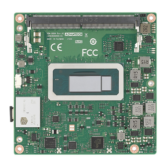
Board Information The figures below indicate the main chips on the SOM-6884 Computer-on-Module. Please be aware of these positions. Customers can design their own carrier boards to avoid mechanical issues and choose thermal solutions with suitable heat dissipa- tion performance. -
Page 25: Mechanical Diagrams
Mechanical Diagrams For more details and 2D/3D models, please consult the Advantech COM support ser- vice website at http://com.advantech.com. Figure 2.3 Board Mechanical Diagram - Front SOM-6884 User Manual... - Page 26 Figure 2.4 Board Mechanical Diagram – Rear Figure 2.5 Board Mechanical Diagram – Side1 SOM-6884 User Manual...
-
Page 27: Assembly Diagram
These figures demonstrate the order of assembly for attaching the thermal module and COM module to the carrier board. Figure 2.6 Assembly Diagram There are 5 reserved screw holes for SOM-6884 to be pre-assembled with the heat spreader. SOM-6884 User Manual... -
Page 28: Assembly Diagram
Assembly Diagram Please consider the CPU and chip height tolerance when designing your thermal solution. Figure 2.7 CPU Height and Tolerance SOM-6884 User Manual... -
Page 29: Chapter 3 Bios
Chapter BIOS This chapter gives BIOS setup information for the SOM-6884 Computer on Module. Sections include: Introduction Entering Setup Hot/Operation Keys Exit BIOS Setup Utility... -
Page 30: Introduction
This information is stored in flash ROM to retain the setup information when the power is turned off. Entering Setup Turn on the computer and then press <DEL> or <ESC> to enter the Setup menu. SOM-6884 User Manual... -
Page 31: Main Setup
Date using the <Arrow> keys. Enter new values through the keyboard. Press the <Tab> key or the <Arrow> keys to move between fields. The date must be entered in MM/DD/YY format. The time must be entered in HH:MM:SS format. SOM-6884 User Manual... -
Page 32: Advanced Bios Features Setup
Advanced BIOS Features Setup Select the Advanced tab from the SOM-6884 Setup screen to enter the Advanced BIOS Setup screen. Users can select any item in the left frame of the screen, such as CPU Configuration, to go to the sub-menu for that item. Users can display an Advanced BIOS Setup option by highlighting it using the <Arrow>... -
Page 33: Cpu Configuration
Cores and E-cores are looked at together. When both are {0,0}, P-code will enable all cores. Active Efficient-Cores Number of E-cores to enable in each processor package. Note: Number of Cores and E-cores are looked at together. When both are {0,0}, P-code will enable all cores. SOM-6884 User Manual... -
Page 34: Power & Performance
3.4.2 Power & Performance Figure 3.5 Power & Performance CPU - Power Management Control CPU - Power Management Control Options GT - Power Management Control GT - Power Management Control Options SOM-6884 User Manual... - Page 35 Turbo Mode Enable/Disable processor Turbo Mode (requires EMTTM enabled). AUTO means enabled. Config TDP Configurations TDP Configurations. C States Enable/Disable CPU Power Management. Allows CPU to go to C states when it's not 100% utilized. SOM-6884 User Manual...
- Page 36 Power Limit 2 value in Milliwatts. BIOS will round to the nearest 1/8W when pro- gramming. 0 = no custom override. For 12.50W, enter 12500. Processor applies control polices such that the package power does not exceed this limit. SOM-6884 User Manual...
- Page 37 Custom value for Turbo Activation Ratio. Needs to be configured with valid val- ues form LFM to Max Turbo. 0 means to not use a custom value. 3.4.2.3 GT - Power Management Control Figure 3.8 GT - Power Management Control RC6(Render Standby) Check to enable render standby support. SOM-6884 User Manual...
-
Page 38: Pch-Fw Configuration
When Disabled, ME will be put into ME Temporarily Disabled Mode. ME Unconfig on RTC Clear When Disabled, ME will not be unconfigured on RTC clear. Firmware Update Configuration Configure Management Engine Technology Parameters. SOM-6884 User Manual... - Page 39 3.4.3.1 Firmware Update Configuration Figure 3.10 FW Update Configuration ME FW Image Re-Flash Enable/Disable the ME FW Image Re-Flash Function. FW Update Enable/ Disable the ME FW update function. SOM-6884 User Manual...
-
Page 40: Trusted Computing
TPM 2.0 devices, Auto will support both with the default set to TPM 2.0 devices if not found, TPM 1.2 devices will be enumerated. Disable Block Sid Override to allow SID authentication in TCG Storage device. SOM-6884 User Manual... -
Page 41: Acpi Settings
Enables or Disables the system’s ability to hibernate (OS/S4 Sleep State). This option may not be effective with some OS. ACPI Sleep State Select the highest ACPI sleep state the system will enter when the SUSPEND button is pressed. SOM-6884 User Manual... -
Page 42: Embedded Controller
Serial Port 1 Configuration Set Parameters of Serial Port 1 (COMA). Serial Port 2 Configuration Set Parameters of Serial Port 2 (COMB). Hardware Monitor Monitor hardware status. CAN0 Control Enable/Disable CAN0 controller on RDC-IS200. SOM-6884 User Manual... - Page 43 Enable/Disable SMBus0 controller on RDC-IS200. 3.4.6.1 Serial Port 1 Configuration Figure 3.14 Serial Port 1 Configuration Serial Port Enable or Disable Serial Port (COM). Change Settings Select an optimal setting for Super IO Device. SOM-6884 User Manual...
-
Page 44: Serial Port Console Redirection
3.4.7 Serial Port Console Redirection Figure 3.15 Serial Port Console Redirection Console Redirection Console Redirection Enable or Disable. Legacy Console Redirection Legacy Console Redirection Settings. Console Redirection EMS Console Redirection Enable or Disable. SOM-6884 User Manual... - Page 45 When Bootloader is selected, then Legacy Console Redirection is disabled before booting to the legacy OS. When Always Enable is selected, then Legacy Console Redirection is enabled for the legacy OS. Default setting for this option is set to Always Enable. SOM-6884 User Manual...
-
Page 46: Usb Configuration
Maximum time the device will take before it properly reports itself to the Host Controller. 'Auto' uses the default value: for a Root port it is 100 ms, for a Hub port the delay is taken from the Hub descriptor. SOM-6884 User Manual... -
Page 47: Network Stack Configuration
3.4.9 Network Stack Configuration Figure 3.18 Network Stack Configuration Network Stack Enable/Disable UEFI Network Stack. SOM-6884 User Manual... -
Page 48: Csm Configuration
3.4.10 CSM Configuration Figure 3.19 CSM Configuration CSM Support Enable/Disable CSM support. SOM-6884 User Manual... -
Page 49: Oem Configuration
3.4.11 OEM Configuration Figure 3.20 OEM Configuration SATA_LED/SPKR Pin Control Select the GPP_B14 pin function to Serial ATA LED or Speaker Output. Hybrid: SPKR in pre-boot, SATA LED in runtime. SOM-6884 User Manual... -
Page 50: Tls Auth Configuration
3.4.12 Tls Auth Configuration Figure 3.21 Tls Auth Configuration Server CA Configuration Press <Enter> to configure Sever CA. Client Cert Configuration SOM-6884 User Manual... -
Page 51: Intel® Ethernet Controller I226-It -00:A0:C9:00:00:00
® 3.4.13 Intel Ethernet Controller I226-IT -00:A0:C9:00:00:00 ® Figure 3.22 Intel Ethernet Controller I226-IT SOM-6884 User Manual... -
Page 52: Chipset Setup
Chipset Setup Figure 3.23 Chipset Setup System Agent (SA) Configuration System Agent Parameters PCH-I0 Configuration PCH parameters SOM-6884 User Manual... -
Page 53: System Agent (Sa) Configuration
VT-d capability Above 4GB MMIO BIOS Assignment Enable/Disable above 4GB memory mapped IO BIOS assignment. This is enabled automatically when the aperture size is set to 2048MB. Program Grant Count Enable/Disable Programming of Grant Count. SOM-6884 User Manual... - Page 54 3.5.1.1 Memory Configuration Figure 3.25 Memory Configuration 3.5.1.2 Graphics Configuration Figure 3.26 Graphics Configuration SOM-6884 User Manual...
- Page 55 VGA modes will be supported only on the pri- mary display. LCD Panel Type Select the LCD panel used by the Internal Graphics Device by selecting the appropriate setup item. Panel Security SOM-6884 User Manual...
- Page 56 Figure 3.28 PCI Express Configuration Compliance Test Mode Enable when using the Compliance Load board. PCI Express Root Port 1 (PEG_4) PCI Express Root Port 2 (PEG_8) PCI Express Root Port 3 (PEG_NVMe) SOM-6884 User Manual...
- Page 57 ASPM Set the ASPM Level: Force L0s- Force all links to L0s State AUTO – BIOS auto configure DISABLE – Disables ASPM Hot Plug PCI Express Hot Plug Enable/Disable. PCIe Speed Configure PCIe Speed. SOM-6884 User Manual...
- Page 58 PCIe Express Power Gating Enable/Disable for each root port. ASPM Set the ASPM Level: Force L0s- Force all links to L0s State AUTO – BIOS auto configure DISABLE – Disables ASPM PCIe Speed Configure PCIe Speed. SOM-6884 User Manual...
- Page 59 ASPM Set the ASPM Level: Force L0s- Force all links to L0s State AUTO – BIOS auto configure DISABLE – Disables ASPM Hot Plug PCI Express Hot Plug Enable/Disable. PCIe Speed Configure PCIe Speed. SOM-6884 User Manual...
-
Page 60: Pch-Io Configuration
Specify what state to go to when power is re-applied after a power failure (G3 state). Flash Protection Range Register (FPRR) Enable Flash Protection Range Registers. SPD Write Disable Enable/Disable setting SPD Write Disable. For security recommendations, SPD write disable bit must be set. SOM-6884 User Manual... - Page 61 PCI Express Root Port 5 (PCIE_0) PCI Express Root Port 6 (PCIE_1) PCI Express Root Port 7 (PCIE_2) PCI Express Root Port 8 (PCIE_3) PCI Express Root Port 9 (PCIE_LAN) PCI Express Root Port 10 (PCIE_5) SOM-6884 User Manual...
- Page 62 ASPM Set the ASPM Level: Force L0s- Force all links to L0s State AUTO – BIOS auto configure DISABLE – Disables ASPM Hot Plug PCI Express hot plug enable/disable PCIe Speed Configure PCIe Speed. SOM-6884 User Manual...
- Page 63 Figure 3.35 SATA Drives SATA Controller(s) Enable/Disable SATA Device. SATA Controller Speed Indicates the maximum speed the SATA controller can support. Port 0 Enable or Disable SATA Port. Port 1 Enable or Disable SATA Port. SOM-6884 User Manual...
- Page 64 3.5.2.3 USB Configuration Figure 3.36 USB Configuration xDCI Support Enable/Disable Xdci (USB OTG Device). USB Port Disable Override Selectively Enable/Disable the corresponding USB port from reporting a Device Connection to the controller. SOM-6884 User Manual...
- Page 65 Enable/Disable the PCH BIOS lock enable feature. Required to be Enabled to ensure SMM protection of flash. Force Unlock on All GPIO Pads If Enabled, BIOS will force all GPIO pads to be in the unlocked state. SOM-6884 User Manual...
- Page 66 3.5.2.5 HD Audio Subsystem Configuration Settings Figure 3.38 HD Audio Subsystem Configuration Settings HD Audio Control Detection of the HD-Audio device. Disabled=HDA will be unconditionally disabled. Enabled=HDA will be unconditionally enabled. SOM-6884 User Manual...
- Page 67 PCI CFG Space will still be visible. This is needed to allow PCI enumerator access functions above 0 in a multifunction device. The following devices depend on each other: I2C0 and I2C1,2,3 UART0 and UART1,SPI0,1 UART2 and I2C4,5 SOM-6884 User Manual...
-
Page 68: Security Chipset
Serial IO I2C1 Settings Configure SerialIO Controller. Serial IO SPIO Settings Configure SerialIO Controller. Security Chipset Figure 3.40 Security Chipset Administrator Password Set Administrator Password. User Password Set User Password. Secure Boot Secure Boot Configuration. SOM-6884 User Manual... -
Page 69: Secure Boot
Restore Factory Keys Force System to User Mode. Install factory default Secure Boot Key databases. Key Management Enables expert users to modify Secure Boot Policy variables without variable authentication. SOM-6884 User Manual... -
Page 70: Boot Setup
Bootup NumLock State Select the keyboard NumLock state. Quiet Boot Enables or Disables Quiet Boot option. Boot Option #1 Sets the system boot order. Boot Option #2 Sets the system boot order. SOM-6884 User Manual... -
Page 71: Save & Exit
Restore/Load default values for all the setup options. Save as User Defaults Save the changes done so far as user defaults. Restore User Defaults Restore the user defaults to all the setup options. Boot Override SOM-6884 User Manual... - Page 72 SOM-6884 User Manual...
-
Page 73: Chapter 4 S/W Introduction & Installation
Chapter S/W Introduction & Installation Sections include: S/W Introduction Driver Installation Advantech iManager... -
Page 74: S/W Introduction
S/W Introduction The mission of Advantech Embedded Software Services is to "Enhance quality of life with Advantech platforms and Microsoft Windows embedded technology". We enable Windows Embedded software products on Advantech platforms to more effectively support the embedded computing community. Customers are freed from the hassle of dealing with multiple vendors (hardware suppliers, system integrators, embedded OS distributors) for projects. - Page 75 SOM-6884 User Manual...
- Page 76 SOM-6884 User Manual...
-
Page 77: Appendix A Pin Assignments
Appendix Pin Assignments... -
Page 78: Som-6884 Pin Assignments
SOM-6884 Pin Assignments This section gives SOM-6884 pin assignments on the COM Express connector which is compliant with COMR.0 R3.1 Type 6 pin-out definitions. More details on how to use these pins and for design reference, please contact Advantech for a design guide, checklist, reference schematic, and other hardware/software support. - Page 79 Table A.1: SOM-6884 Pin Assignments GND (FIXED) GND (FIXED) USB2- USB3- USB2+ USB3+ USB_2_3_OC# USB_0_1_OC# USB0- USB1- USB0+ USB1+ VCC_RTC ESPI_EN# RSMRST_OUT# USB0_HOST_PRSNT GBE0_SDP SYS_RESET# LPC_SERIRQ/ESPI_CS1# CB_RESET# GND (FIXED) GND (FIXED) PCIE_TX5+ PCIE_RX5+ PCIE_TX5- PCIE_RX5- GPI0 GPO1 PCIE_TX4+ PCIE_RX4+ PCIE_TX4-...
- Page 80 Table A.1: SOM-6884 Pin Assignments PCIE_CLK_REF- VGA_RED GND (FIXED) GND (FIXED) SPI_POWER VGA_GRN SPI_MISO VGA_BLU GPO0 VGA_HSYNC SPI_CLK VGA_VSYNC SPI_MOSI VGA_I2C_CK TPM_PP VGA_I2C_DAT TYPE10# SPI_CS# SER0_TX GP_SPI_MISO SER0_RX GP_SPI_CK A100 GND (FIXED) B100 GND (FIXED) A101 SER1_TX B101 FAN_PWMOUT A102...
- Page 81 Table A.1: SOM-6884 Pin Assignments PCIE_RX7- PCIE_TX7- DDI1_HPD SML0_CLK SML0_DAT DDI1_PAIR0+/USB4_1_SSTX0+ SML1_CLK DDI1_PAIR0-/USB4_1_SSTX0- SML1_DAT USB4_PD_I2C_CLK DDI1_PAIR1+/USB4_1_SSRX0+ USB4_PD_I2C_DAT DDI1_PAIR1-/USB4_1_SSRX0- GND (FIXED) GND (FIXED) DDI2_CTRLCLK_AUX+/ DDI1_PAIR2+/USB4_1_SSTX1+ USB4_2_AUX+ DDI2_CTRLDATA_AUX-/ DDI1_PAIR2-/USB4_1_SSTX1- USB4_2_AUX- DDI2_DDC_AUX_SEL DDI1_DDC_AUX_SEL USB4_2_LSTX USB4_2_LSRX DDI3_CTRLCLK_AUX+ DDI1_PAIR3+/USB4_1_SSRX1+ DDI3_CTRLDATA_AUX- DDI1_PAIR3-/USB4_1_SSRX1- DDI3_DDC_AUX_SEL DDI3_PAIR0+ DDI2_PAIR0+/USB4_2_SSTX0+ DDI3_PAIR0-...
- Page 82 Table A.1: SOM-6884 Pin Assignments PEG_RX5+ PEG_TX5+ PEG_RX5- PEG_TX5- GND (FIXED) GND (FIXED) PEG_RX6+ PEG_TX6+ PEG_RX6- PEG_TX6- PEG_RX7+ PEG_TX7+ PEG_RX7- PEG_TX7- PEG_RX8+ PEG_TX8+ PEG_RX8- PEG_TX8- GND (FIXED) GND (FIXED) PEG_RX9+ PEG_TX9+ PEG_RX9- PEG_TX9- PEG_RX10+ PEG_TX10+ PEG_RX10- PEG_TX10- PEG_RX11+ PEG_TX11+ PEG_RX11-...
-
Page 83: Appendix B Watchdog Timer
Appendix Watchdog Timer This appendix gives you informa- tion for the watchdog timer pro- gramming on the SOM-6884 CPU System on Module. Sections include: Programming the Watchdog Timer... -
Page 84: Programming The Watchdog Timer
BIOS, and then sets to EC. Only Win10 supports this. In other OS, it will still use the IRQ number from the BIOS setting as usual. For details, please refer to the iManager & Software API User Manual. SOM-6884 User Manual... -
Page 85: Appendix C Programming Gpio
Appendix Programming GPIO This Appendix illustrates the Gen- eral Purpose Input and Output pin settings. Sections include: GPIO Register... -
Page 86: Gpio Register
Table C.1: GPIO Register GPIO Byte Mapping H/W Pin Name BIT0 GPI0 BIT1 GPI1 BIT2 GPI2 BIT3 GPI3 BIT4 GPO0 BIT5 GPO1 BIT6 GPO2 BIT7 GPO3 For details, please refer to the iManager and Software API User Manual. SOM-6884 User Manual... -
Page 87: Appendix D System Assignments
Appendix System Assignments This appendix gives you informa- tion about the system resource allocation on the SOM-6884 CPU System on Module Sections include: System I/O ports DMA Channel Assignments Interrupt Assignments 1st MB Memory Map... -
Page 88: System I/O Ports
0x000000A4-0x000000A5 Programmable interrupt controller 0x000000A8-0x000000A9 Programmable interrupt controller 0x000000AC-x000000AD Programmable interrupt controller 0x000000B0-0x000000B1 Programmable interrupt controller 0x000000B4-0x000000B5 Programmable interrupt controller 0x000000B8-0x000000B9 Programmable interrupt controller 0x000000BC-0x000000BD Programmable interrupt controller 0x000004D0-0x000004D1 Programmable interrupt controller 0x00003090-0x00003097 Standard SATA AHCI Controller SOM-6884 User Manual... - Page 89 Communications Port (COM1) 0x000002F8-0x000002FF Communications Port (COM2) 0x00001854-0x00001857 Motherboard resources 0x00000000-0x00000CF7 PCI Express Root Complex 0x00000D00-0x0000FFFF PCI Express Root Complex 0x00000040-0x00000043 System timer 0x00000050-0x00000053 System timer 0x00003000-0x0000303F Intel® Iris® Xe Graphics 0x00002000-0x000020FE Motherboard resources 0x0000EFA0-0x0000EFBF Intel® SMBus - 51A3 SOM-6884 User Manual...
-
Page 90: Interrupt Assignments
Microsoft ACPI-Compliant System IRQ 63 Microsoft ACPI-Compliant System IRQ 64 Microsoft ACPI-Compliant System IRQ 65 Microsoft ACPI-Compliant System IRQ 66 Microsoft ACPI-Compliant System IRQ 67 Microsoft ACPI-Compliant System IRQ 68 Microsoft ACPI-Compliant System IRQ 69 Microsoft ACPI-Compliant System SOM-6884 User Manual... - Page 91 Microsoft ACPI-Compliant System IRQ 110 Microsoft ACPI-Compliant System IRQ 111 Microsoft ACPI-Compliant System IRQ 112 Microsoft ACPI-Compliant System IRQ 113 Microsoft ACPI-Compliant System IRQ 114 Microsoft ACPI-Compliant System IRQ 115 Microsoft ACPI-Compliant System IRQ 116 Microsoft ACPI-Compliant System SOM-6884 User Manual...
- Page 92 Microsoft ACPI-Compliant System IRQ 157 Microsoft ACPI-Compliant System IRQ 158 Microsoft ACPI-Compliant System IRQ 159 Microsoft ACPI-Compliant System IRQ 160 Microsoft ACPI-Compliant System IRQ 161 Microsoft ACPI-Compliant System IRQ 162 Microsoft ACPI-Compliant System IRQ 163 Microsoft ACPI-Compliant System SOM-6884 User Manual...
- Page 93 Microsoft ACPI-Compliant System IRQ 204 Microsoft ACPI-Compliant System IRQ 256 Microsoft ACPI-Compliant System IRQ 257 Microsoft ACPI-Compliant System IRQ 258 Microsoft ACPI-Compliant System IRQ 259 Microsoft ACPI-Compliant System IRQ 260 Microsoft ACPI-Compliant System IRQ 261 Microsoft ACPI-Compliant System SOM-6884 User Manual...
- Page 94 Microsoft ACPI-Compliant System IRQ 302 Microsoft ACPI-Compliant System IRQ 303 Microsoft ACPI-Compliant System IRQ 304 Microsoft ACPI-Compliant System IRQ 305 Microsoft ACPI-Compliant System IRQ 306 Microsoft ACPI-Compliant System IRQ 307 Microsoft ACPI-Compliant System IRQ 308 Microsoft ACPI-Compliant System SOM-6884 User Manual...
- Page 95 Microsoft ACPI-Compliant System IRQ 349 Microsoft ACPI-Compliant System IRQ 350 Microsoft ACPI-Compliant System IRQ 351 Microsoft ACPI-Compliant System IRQ 352 Microsoft ACPI-Compliant System IRQ 353 Microsoft ACPI-Compliant System IRQ 354 Microsoft ACPI-Compliant System IRQ 355 Microsoft ACPI-Compliant System SOM-6884 User Manual...
- Page 96 Microsoft ACPI-Compliant System IRQ 396 Microsoft ACPI-Compliant System IRQ 397 Microsoft ACPI-Compliant System IRQ 398 Microsoft ACPI-Compliant System IRQ 399 Microsoft ACPI-Compliant System IRQ 400 Microsoft ACPI-Compliant System IRQ 401 Microsoft ACPI-Compliant System IRQ 402 Microsoft ACPI-Compliant System SOM-6884 User Manual...
- Page 97 Microsoft ACPI-Compliant System IRQ 443 Microsoft ACPI-Compliant System IRQ 444 Microsoft ACPI-Compliant System IRQ 445 Microsoft ACPI-Compliant System IRQ 446 Microsoft ACPI-Compliant System IRQ 447 Microsoft ACPI-Compliant System IRQ 448 Microsoft ACPI-Compliant System IRQ 449 Microsoft ACPI-Compliant System SOM-6884 User Manual...
- Page 98 Microsoft ACPI-Compliant System IRQ 490 Microsoft ACPI-Compliant System IRQ 491 Microsoft ACPI-Compliant System IRQ 492 Microsoft ACPI-Compliant System IRQ 493 Microsoft ACPI-Compliant System IRQ 494 Microsoft ACPI-Compliant System IRQ 495 Microsoft ACPI-Compliant System IRQ 496 Microsoft ACPI-Compliant System SOM-6884 User Manual...
- Page 99 Intel® Ethernet Controller I226-IT IRQ 4294967263 Intel® Ethernet Controller I226-IT IRQ 4294967262 Intel® Ethernet Controller I226-IT IRQ 4294967261 Intel® Ethernet Controller I226-IT IRQ 4294967260 Intel® Ethernet Controller I226-IT IRQ 4294967259 Intel® Ethernet Controller I226-IT IRQ 4294967258 Intel® Ethernet Controller I226-IT SOM-6884 User Manual...
-
Page 100: 1St Mb Memory Map
Intel® Serial IO I2C Host Controller - 51E8 0x0000-0xFFFFFF Intel® Iris® Xe Graphics 0x0000-0xFFFFFFF Intel® Iris® Xe Graphics 0xFFEFB000-0xFFEFBFFF Intel® Serial I/O SPI Host Controller - 51AA 0x50500000-0x505FFFFF Intel® Ethernet Controller I226-IT 0x50600000-0x50603FFF Intel® Ethernet Controller I226-IT 0x1128000-0x11280FF Intel® SMBus - 51A3 SOM-6884 User Manual... - Page 101 SOM-6884 User Manual...
- Page 102 No part of this publication may be reproduced in any form or by any means, electronic, photocopying, recording or otherwise, without prior written permis- sion of the publisher. All brand and product names are trademarks or registered trademarks of their respective companies. © Advantech Co., Ltd. 2023...
Need help?
Do you have a question about the SOM-6884 and is the answer not in the manual?
Questions and answers