
Related Manuals for Advantech RSB-4710


Summary of Contents for Advantech RSB-4710
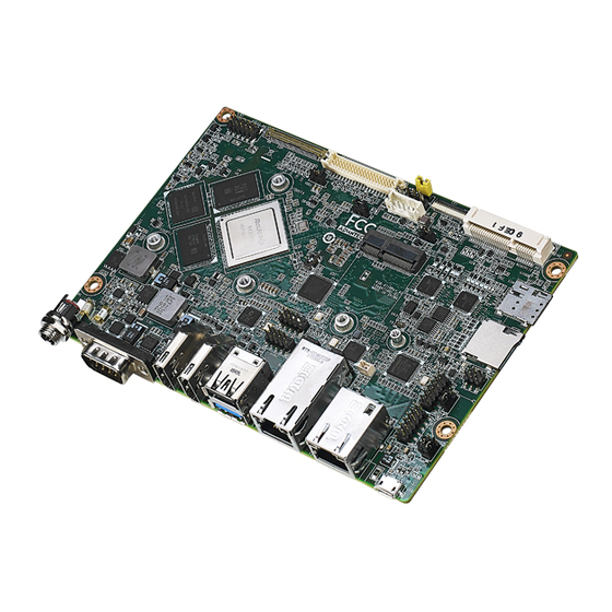
- Page 1 User Manual RSB-4710 3.5” Single-Board Computer with Rockchip Arm® Cortex®-A72 Processor...
- Page 2 The documentation and the software included with this product are copyrighted 2020 by Advantech Co., Ltd. All rights are reserved. Advantech Co., Ltd. reserves the right to improve the products described in this manual at any time without notice. No part of this manual may be reproduced, copied, translated, or transmitted in any form or by any means without the prior written permission of Advantech Co., Ltd.
- Page 3 Packing List Before installation, ensure that the following items have been shipped: 1 x RSB-4710 SBC Safety Precautions – Static Electricity Follow this simple precaution to protect yourself from harm and the products from...
- Page 4 RSB-4710 2GDDR,16GB eMMC, 0 ~ 60 °C/32 ~ 140 °F RSB-R4710WO-XNA1E RSB-4710 2GDDR,16GB eMMC, -20 ~ 85 °C/-4 ~ 185 °F RSB-R4710CO-XLA1E RSB-4710 2GDDR,16GB eMMC, lite, 0 ~ 60 °C/32 ~ 140 °F RSB-R4710WO-XLA1E RSB-4710 2GDDR,16GB eMMC, lite, -20 ~ 85 °C/-4 ~ 185 °F RSB-4710 User Manual...
- Page 5 Antenna cable SMA(F)/MHF 15cm 1750007990-01 Antenna 4G/LTE full band L=11 cm 50 Ohm SQF-MSDM1-8G-21C SQF micro SD C10 MLC 8G (-25 ~ 85 °C/-13 ~ 185 °F) *Contact Advantech to obtain a suitable cellular module for your region. RSB-4710 User Manual...
- Page 6 RSB-4710 User Manual...
-
Page 7: Table Of Contents
Figure 2.24Micro USB Connector..........31 Figure 2.25Reset Button............. 32 Figure 2.26GPIO Pin Header............32 Figure 2.27SPI Pin Header............33 Figure 2.28I2C Connector ............33 LED ......................34 Quick Start Guide..................34 2.6.1 Debug Port Connection............... 34 2.6.2 Debug Port Setting..............35 RSB-4710 User Manual... - Page 8 Obtain Android Source Code............38 3.2.4 Building an Android 7.1.2 image..........39 GPIO ....................... 40 UART ...................... 42 3.4.1 RSB-4710 UART ................ 42 3.4.2 How to Configure RS-232/485 Mode.......... 42 Audio....................... 43 SD/MMC Card/USB Disk ................ 43 3.6.1 Browse the SD................43 HDMI .......................
-
Page 9: Chapter 1 General Introduction
Chapter General Introduction This chapter gives background information regarding RSB-4710. Introduction Specification... -
Page 10: Introduction
I/O, including 2 x GbE, 6 x serial ports, 6 x USB, and 5 x GPIO, as well as 1 x mini PCIe, 1 x M.2, and 1 x SIM card slot for integrating Wi-Fi, Blue- tooth, and 3G/4G modules. RSB-4710 provides the ideal system for kiosk, POS, and vending machine applications. -
Page 11: Mechanical Specifications
Operating Temperature: 0 ~ 60 °C/32 ~ 104 °F; -20 ~ 85 °C/-4 ~ 185 °F Operating Humidity: 5 ~ 95% relative humidity, non-condensing Storage Temperature: -40 ~ 85 °C/-40~185 °F Storage Humidity: 60 °C/140 °F @ 95% RH non-condensing RSB-4710 User Manual... -
Page 12: Block Diagram
RS-232/debug Mini PCIe & Quad Cortex-A53 USB251 USB host 2.0 UART4 Transceiver RS-232 Nano SIM 7-JZX I2C/SPI I2C/SPI 3 x USB 2.0 GPIO 5 x GPIO 2 x RS-232/485 FT4232 SDIO O Micro SD 2 x RS-232 RSB-4710 User Manual... -
Page 13: Chapter 2 Hardware Installation
Chapter Hardware Installation This chapter provides mechanical and connector information. Jumper Information Connector Information Mechanical Drawing Quick Start Guide... -
Page 14: Jumper And Connector Locations
LED POWER BTN SD slot AT & ATX switch M.2 E- Key COM2 RS232/ debug VDD1 SIM slot eDP VDD 3.3/5V Mini- PCIE LVDS Mipi CSI Audio LVDS BKL BLP1 BLP2 LVDS BKL 3.3/5V LVDS BKL 12V RSB-4710 User Manual... -
Page 15: Board Dimensions
Board Dimensions RSB-4710 User Manual... -
Page 16: Jumpers
AT & ATX Mode Switch, default AT mode VDD3 LVDS VDD 3.3V &5V level select, default 3.3V BLP1 LVDS BKL PWR 3.3V&5V level select, default off BLP2 LVDS BKL PWR 12V select, default 12V VDD1 EDP VDD 3.3V &5V level select, default 3.3V RSB-4710 User Manual... -
Page 17: Jumper Settings
2.3.3 Jumper Settings 2.3.3.1 RSB-4710 COM2 can be used as RS-232 or a debug port via J4 selection. UART2 used for COM port and debug mode select Part Number 1653003101 Footprint HD_3x1P_79_D Description Pin header 3 x 1P 2.0 mm 180D(M) DIP 2000-13 WS... - Page 18 2.3.3.3 RSB-4710 COM5 and COM6 can be used as RS-232 or RS-485 via software config- uration, refer to Section 3.4. When set as RS-485, the impedance can be configured on/off. COM5 and COM6 RS-485 impedance on/off Part Number 1653003201-01 Footprint...
- Page 19 Pin header 3 x 1P 2.0 mm 180D(M) DIP 2000-13 WS Setting Function (1-2) 3.3V (2-3) 2.3.3.6 BLP1 RSB-4710 LVDS backlight supports 3.3.V/5V/12V power supply via BLP1/BLP2 selection. BLP1 LVDS BKLT PWR 3.3/5V level select Part number 1653003100 Footprint PH3x1P-2.54 Description Pin header 3 x 1P 2.54 mm 180D(M) DIP 1130-000-03S...
- Page 20 EDP VDD 3.3/5V level select Part Number 1653003101 Footprint HD_3x1P_79_D Description Pin header 3 x 1P 2.0 mm 180D(M) DIP 2000-13 WS Setting Function (1-2) 3.3V (2-3) This pin header is designed for EDP panel VDD level selection. RSB-4710 User Manual...
-
Page 21: Connectors
USB Type A (USB 3.0 and 2.0) USB2 USB pin header USB3 USB pin header LAN1 LAN1 LAN2 LAN2 RTC CONN COM56 COM5 and COM6 with RS-232 or RS-485 COM34 COM3 and COM4 with RS-232 Reset button GPIO CONN RSB-4710 User Manual... -
Page 22: Connector Settings
Line-Out pin header. If earphone functionality is required, an amplifier must be added, and the microphone connected to the Mic-In pin header. RSB-4710 also supports a mono speaker (2.8W 4Ω or 1.5W 8Ω). Use a cable (Advantech part number: 1700031093-01) for Line-Out and Mic-In tests. - Page 23 2.4.2.2 EDP Connector (EDP) RSB-4710 supports one 40- pin EDP connector. The pin definitions are provided below. Signal Name Signal Name EDP_z_TXN3 EDP_z_TXP3 EDP_z_TXN2 EDP_z_TXP2 EDP_z_TXN1 EDP_z_TXP1 EDP_z_TXN0 EDP_z_TXP0 EDP_z_AUX+ EDP_z_AUX- VDD_EDP VDD_EDP VDD_EDP VDD_EDP EDP_HPD BL_ENABLE BL_PWM_DIM BL_PWR BL_PWR...
- Page 24 2.4.2.3 LVDS Connector (LVDS) RSB-4710 provides an LVDS 20 x 2-pin board-to-board connector for one port of sin- gle or dual-channel 18/24-bit LVDS. To avoid damaging the LCD panel, ensure that the voltage is correct before connecting an LVDS panel (refer to Section 2.3.3.5 for the VDD3 jumper settings and the LCD datasheet).
- Page 25 To avoid damaging the LCD panel, ensure that the voltage is correct before connect- ing an LVDS panel (refer to Section 2.3.3.6 for the BLP1 jumper settings and the LCD datasheet). Description +VDD_BKLT LVDS_BLEN LVDS_PWM Figure 2.4 LVDS Backlight Connector RSB-4710 User Manual...
- Page 26 2.4.2.5 MIPI CSI Connector (CSI) RSB-4710 supports the MIPI CSI interface. The pin definitions are provided below. Signal Name Signal Name +V3_CAMAF_B +V3_CAMAF_B MIPI_RX0_D0P MIPI_RX0_D0N MIPI_RX0_D1P MIPI_RX0_D1N MIPI_RX0_D2P MIPI_RX0_D2N CAM1_RST#_C MIPI_RX0_D3P MIPI_RX0_D3N MIPI_RX0_CLKP MIPI_RX0_CLKN I2C_CSI1_CK I2C_CSI1_DAT CAM1_PWR#_C CAM0_X_MCK CAM1_PWR#_C Figure 2.5 MIPI CSI Connector...
- Page 27 2.4.2.6 Mini PCIe (MINIPCIE) RSB-4710 supports the mini PCIe interface. The pin definitions are provided below. Signal Name Signal Name +3.3V_PCIe UIM_PWR UIM_DATA UIM_CLK UIM_RST W_DISABLE# PERST_M# USB_MINIPCIE_N USB_MINIPCIE_P +3.3V_PCIe +3.3V_PCIe LED_WWAN# +3.3V_PCIe Figure 2.6 Mini PCIe Connector RSB-4710 User Manual...
- Page 28 2.4.2.7 Nano SIM Card (SIM) RSB-4710 features one onboard nano SIM card slot for 4G integration. Insert a valid mini PCIe card and SIM card to connect to a 4G network. Description SIM_VCC SIM_RST SIM_CLK SIM_DATA Figure 2.7 Nano SIM Card...
- Page 29 2.4.2.8 M.2 (M2) RSB-4710 supports a socket1 connectivity type 2230 S1, S2, S3 E-key M.2 interface. The pin definitions are provided below. Signal Name Signal Name +V3.3A_M.2 USB_M.2+ +V3.3A_M.2 USB_M.2- SDIO0_z_CLK SDIO0_z_CMD SDIO0_z_D0 SDIO0_z_D1 SDIO0_z_D2 SDIO0_z_D3 BT_z_WAKE_L WIFI_z_WAKE_L UART0_z_RXD NGFF_WIFI_REG_ON...
- Page 30 Figure 2.8 M.2 Connector 2.4.2.9 Micro SD (SD) RSB-4710 supports an SD/MMC card in Class 2, 4, 6, 8, and 10 and up to 64GB. Signal Name SDMMC0_z_D2 SDMMC0_z_D3 SDMMC0_z_CMD +V3V_SD SDMMC0_z_CLK SDMMC0_z_D0 SDMMC0_z_D1 SD_CD Figure 2.9 Micro SD RSB-4710 User Manual...
- Page 31 2.4.2.10 Power Button and LED (BTN) RSB-4710 supports a power button, power LED light, and 4G LED light via two 3-pin headers. A cable (Advantech part number: 1700031120-01) can be used to connect the power button. Pin Name PWR_BTN (PWR_BTN+)
- Page 32 The port can support RS-232 communication. Description COM4_RXD COM4_TXD Figure 2.12 COM1 Connector 2.4.2.13 RS-232/Debug Port (COM2/DEBUG) RSB-4710 can communicate with a host server (Windows or Linux) via a debug cable (Advantech part number: 1700028481-01). Description COM2_TXD COM2_RXD Figure 2.13 COM2/Debug Connector RSB-4710 User Manual...
- Page 33 2.4.2.14 HDMI Connector (HDMI1, HDMI2) RSB-4710 features two HDMI ports. The pin definitions are provided below. Description Description HDMI1_z_DATA2+ HDMI1_z_CLK- HDMI1_z_DATA2- HDMI1_z_CEC HDMI1_z_DATA1+ HDMI1_DDC_CLK HDMI1_z_DATA1- HDMI1_DDC_DATA HDMI1_z_DATA0+ +5V_HDMI HDMI1_z_DATA0- HDMI1_HPD HDMI1_z_CLK+ Figure 2.14 HDMI1 Connector Description Description HDMI2_z_2+ HDMI2_z_CLK- HDMI2_z_2-...
- Page 34 Figure 2.15 HDMI2 Connector 2.4.2.15 USB Type A Connector (USB1) RSB-4710 supports one standard USB 3.0 and one USB 2.0 Type A connector on the coastline. Description +USBV1 USB_D1- USB_D1+ USB3X0_z_RX- USB3X0_z_RX+ USB3X0_z_TX- USB3X0_z_TX+ +VUSB3 USB_D2- USB_D2+ Figure 2.16 USB Connector...
- Page 35 2.4.2.16 USB (Internal Pin Header) (USB2, USB3) RSB-4710 provides three extra internal USB 2.0 ports via pin header USB2 and USB3. The USB2 pin definitions are provided below. Description Description +VUSB3 +VUSB3 USB_z_P2_DM USB_z_P1_DM USB_z_P2_DP USB_z_P1_DP Figure 2.17 USB2 Pin Header The USB3 pin definitions are provided below.
- Page 36 2.4.2.17 Ethernet Connector (LAN1) RSB-4710 provides one RJ45 LAN interface connector, which is compliant with 1000 BASE-T IEEE 802.3ab, 100 BASE-TX IEEE 802.3u, and 10 BASE-T IEEE 802.3. The Ethernet ports feature a standard RJ-45 jack connector with LED indicators at the front to indicate the Active/Link and Speed status.
- Page 37 2.4.2.18 Ethernet Connector (LAN2) RSB-4710 provides one RJ45 LAN interface connector, which is compliant with 1000 BASE-T IEEE 802.3ab, 100 BASE-TX IEEE 802.3u, and 10 BASE-T IEEE 802.3.The Ethernet ports feature a standard RJ-45 jack connector with LED indicators at the front to indicate the Active/Link and Speed status.
- Page 38 RSB-4710 provides a two-port RS-232/458 pin header. Users can configure RS-232/ 485 mode on uboot. The system must be reset after switching to RS-485 from RS- 232. A cable (Advantech part number: 1700031060-01) can be used for connecting a standard D-SUB 9P connector.
- Page 39 2.4.2.21 Internal RS-232 (COM34) RSB-4710 provides a two-port RS-232 pin header that can supply 5V or 12V power via J3 selection. Description COM6_TXD COM6_RXD COM6_RTS# COM6_CTS# COM6_PWR COM7_PWR COM7_CTS# COM7_RTS# COM7_RXD COM7_TXD Figure 2.23 Internal RS-232/485 Pin Header 2.4.2.22 Micro USB Connector (OTG) RSB-4710 supports one USB OTG port on the coastline.
- Page 40 RSB-4710 supports a reset button on the coastline. Description +V3.3A +VPP_OTP GND_F GND_F Figure 2.25 Reset Button 2.4.2.24 GPIO (CN3) RSB-4710 provides one internal GPIO interface via a 10-pin wafer box. Pin Name Pin Name GPIO2 GPIO6 GPIO1 GPIO5 +3.3V GPIO4 Figure 2.26 GPIO Pin Header...
- Page 41 2.4.2.25 SPI (CN1) RSB-4710 provides one SPI via a 6-pin wafer box. Description +VCC_3V0 SPI2_CSN0 SPI2_CLK SPI2_TXD SPI2_RXD Figure 2.27 SPI Pin Header 2.4.2.26 I2C (CN2) RSB-4710 provides one I2C via a 5-pin wafer box. Description +3.3V I2C4_SCL_CONN I2C4_SDA_CONN Touch_INT# Figure 2.28 I2C Connector...
-
Page 42: Led
Power LED LED3 WWAN LED Quick Start Guide 2.6.1 Debug Port Connection Connect the debug cable to the RSB-4710 debug port (see Figure 2.3). Item Part Number Picture Debug cable 1700021565-11 Debug cable 1700026611-01 Connect the other end of the debug cable to the PC directly or via a USB-to-RS- 232 cable. -
Page 43: Debug Port Setting
Open HyperTerminal on the Windows PC and configure the settings as shown below. Insert a power adapter connector into the DC jack on RSB-4710 to supply power to the board. The bootloader prompt will be displayed on the terminal screen. - Page 44 RSB-4710 User Manual...
-
Page 45: Chapter 3 Software Functionality
Chapter Software Functionality This chapter details software functions on RSB-4710. -
Page 46: Introduction
This chapter explains how to develop software for RSB-4710 to enable users to develop unique applications efficiently. RSB-4710 is designed be developed in a Linux host environment. For now, the offi- cially supported host OS is Ubuntu 16.04 LTS (64 bit). Compatibility problems may occur when using a Windows or Android environment for application development. -
Page 47: Building An Android 7.1.2 Image
$ source build/envsetup.sh Execute the Android lunch command. In this example, the setup is for the production image of Advantech RISC platform device with user debug type. If your device is RSB-4710, you will be sent a "lunch rk3399_rsb4710-userdebug” command. -
Page 48: Gpio
GPIO4 GPIO3_D4 GPIO5 GPIO4_A4 GPIO6 GPIO0_B0 Export GPIO in order to use control GPIO from the user space through sysfs. Export GPIO1. $ echo 72 > /sys/class/gpio/export Set GPIO direction to in/out. $ echo "out" > /sys/class/gpio/gpio72/direction RSB-4710 User Manual... - Page 49 $ echo "in" > /sys/class/gpio/gpio50/direction Change GPIO 1 to 1 and read GPIO 2 value. $ echo 1 > /sys/class/gpio/gpio72/value $ cat /sys/class/gpio/gpio50/value Change GPIO 1 to 0 and read GPIO 2 value. echo 0 > /sys/class/gpio/gpio72/value $ cat /sys/class/gpio/gpio50/value RSB-4710 User Manual...
-
Page 50: Uart
Note: The default value is RS-232. Cp210x supports four ports, but for RSB-4710 only ttyUSB2 and ttyUSB3 support RS-485 mode. In the above command “setenv uart_mode 0x0c”, 0x0c means set bit2(ttyUSB2) and bit3(ttyUSB3) to 1 (0 means to RS-232; 1 means to RS-485). -
Page 51: Audio
Audio Launch “Sound Recorder” for the microphone. Launch “Video” for audio. SD/MMC Card/USB Disk 3.6.1 Browse the SD Launch “Explorer” to browse the SD card or USB disk. RSB-4710 User Manual... -
Page 52: Hdmi
If the HDMI monitor supports audio, the default output will be both HDMI and the onboard audio codec. Multiple Display RSB-4710 supports four display ports: eDP, LVDS (MIPI-to-LVDS), HDMI, and DP (DP-to-HDMI). However, only two ports can be used simultaneously. Default Display Support:... -
Page 53: Enter U-Boot Interrupt Mode
When LVDS is the primary display, configure in u-boot as follows: setenv prmry_screen lvds-g070vw01 setenv extend_screen edp-1920x1080 saveenv reset When eDP is the primary display, configure in u-boot as follows: setenv prmry_screen edp-1920x1080 setenv extend_screen lvds-g070vw01 saveenv reset RSB-4710 User Manual... -
Page 54: Hdmi And Dp (Hdmi2)
When LVDS is the primary display, configure in u-boot as follows: setenv prmry_screen dp-default setenv extend_screen lvds-g070vw01 saveenv reset When DP(HDMI2) is the primary display, configure in u-boot as follows: setenv prmry_screen dp-default setenv extend_screen edp-1920x1080 saveenv reset RSB-4710 User Manual... -
Page 55: Network Setup
Network Setup 3.9.1 Wi-Fi Click Settings. Turn on Wi-Fi. Choose ESSID (for example, Advantech for guest). RSB-4710 User Manual... - Page 56 Input the password. Wi-Fi connected. RSB-4710 User Manual...
-
Page 57: Bluetooth
3.9.2 Bluetooth Click Settings, switch Bluetooth to on to activate Bluetooth. Click any available devices to pair with. After pairing successfully you can now communicate. RSB-4710 User Manual... - Page 58 3.9.3 3G/4G Insert SIM card. Restart the device. If the device does not automatically connect to a network, navigate to the follow- ing location: Settings/More/Cellular Networks/ Access Point Names Then adjust the network settings. RSB-4710 User Manual...
-
Page 59: Ethernet
3.9.4 Ethernet RSB-4710 supports two Ethernet ports (eth0 and eth1). However, Android only sup- ports configuration of eth0 as follows: Config eth0: Click Settings->More->Ethernet Configure Ethernet. There are two IP settings: DHCP IP and static IP DHCP IP - configuration is controlled by the system Static IP - Five fields must be filled: IP Address, Netmask, Gateway, dns1, and dns2. -
Page 60: Iic
Config eth1: Eth1 setting static ip example: $ su # ip rule add from all lookup main pref 9999 # ifconfig eth1 172.12.1.2 netmask 255.255.0.0 3.10 Use i2cdetect cmd to detect iic devices (for example, i2cdetect -y 4). RSB-4710 User Manual... -
Page 61: Chapter 4 Advantech Services
Chapter Advantech Services This chapter outlines Advantech’s Design-In services, technical sup- port, and warranty policy for RSB- 6410. -
Page 62: Risc Design-In Services
Comprehensive document support Design Assistance Service Advantech provides a checklist for engineers to easily check their schematics as well as several services for reviewing customer carrier board schematics. These services aim to help identify design errors before implementation, which saves substantial development time and costs. - Page 63 Advantech has been involved in the industrial computer industry for many years and found that customers usually have the following questions when implementing modu- lar designs.
- Page 64 RISC COM. Design Stage When a product moves into the design stage, Advantech will supply a carrier board design guide for reference. The carrier board design guide provides pin definitions of the COM connector with limitations and recommendations for carrier board design.
-
Page 65: Contact Information
In addition to verifying the product’s functionality, the product’s efficiency must also be tested at this stage, particularly with RISC platforms. Advantech plays a supportive role in helping customers solve problems during the testing and verification process and will provide suggestions and tips as well. -
Page 66: Global Service Policy
The DOA cross-shipment excludes any shipping damage, customized and/or build- to-order products. For products that are not DOA, the return fee to an authorized Advantech repair facil- ity will be at the customer’s expense. The shipping fee for reconstructed products from Advantech back to the customer will be at Advantech’s expense. - Page 67 “Attn. RMA Service Department”. All products must be returned in properly packed ESD material or anti-static bags. Advantech reserves the right to return unrepaired items at the customer's cost if inap- propriately packed. Door-to-Door transportation, such as speed post, is recommended for delivery. Oth- erwise, the sender should bear additional charges such as clearance fees if air cargo shipment methods are used.
- Page 68 tomer who is without warranty. If a product has been repaired by Advantech, and within three months after such a repair the product requires another repair for the same problem, Advantech will con- duct the repair free of charge. However, free repairs do not apply to products that have been misused, abused, or subjected to unauthorized disassembly/modification;...
- Page 69 RSB-4710 User Manual...
- Page 70 No part of this publication may be reproduced in any form or by any means, such as electronically, by photocopying, recording, or otherwise, without prior written permission from the publisher. All brand and product names are trademarks or registered trademarks of their respective companies. © Advantech Co., Ltd. 2020...
Need help?
Do you have a question about the RSB-4710 and is the answer not in the manual?
Questions and answers