Table of Contents
Advertisement
Quick Links
Our company network supports you worldwide with offices in Germany, Austria,
Switzerland, Great Britain and the USA. For more information please contact:
FORTEC Elektronik AG
Hauptniederlassung
Lechwiesenstr. 9
86899 Landsberg am Lech
Telefon:
+49 (0) 8191 91172-0
Telefax:
+49 (0) 8191 21770
E-Mail:
sales@fortecag.de
Internet:
www.fortecag.de
FORTEC Elektronik AG
Büro Wien
Nuschinggasse 12
A-1230 Wien
Telefon:
+43 1 8673492-0
Telefax:
+43 1 8673492-26
E-Mail:
office@fortec.at
Internet:
www.fortec.at
The information contained in this document has been carefully researched and is, to the best
of our knowledge, accurate. However, we assume no liability for any product failures or
damages, immediate or consequential, resulting from the use of the information provided
herein. Our products are not intended for use in systems in which failures of product could
result in personal injury. All trademarks mentioned herein are property of their respective
owners. All specifications are subject to change without notice.
Manual
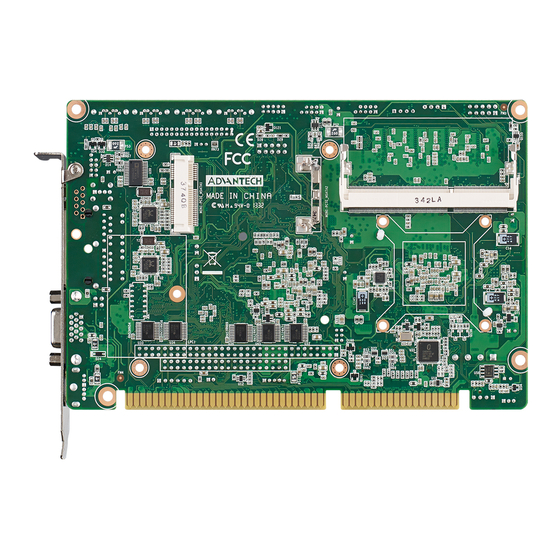
PCA-6763
Advantech
FORTEC Elektronik AG
Büro West
Hohenstaufenring 55
50674 Köln
Telefon:
Telefax:
E-Mail:
Internet:
ALTRAC AG
(Tochter der FORTEC):
Bahnhofstraße 3
CH-5436 Würenlos
Telefon:
Telefax:
E-Mail:
Internet:
+49 (0) 221 272 273-0
+49 (0) 221 272 273-10
west@fortecag.de
www.fortecag.de
+41 (0) 44 7446111
+41 (0) 44 7446161
info@altrac.ch
www.altrac.ch
Advertisement
Table of Contents

Related Manuals for Advantech PCA-6763


Summary of Contents for Advantech PCA-6763
- Page 1 Manual PCA-6763 Advantech Our company network supports you worldwide with offices in Germany, Austria, Switzerland, Great Britain and the USA. For more information please contact: FORTEC Elektronik AG FORTEC Elektronik AG Hauptniederlassung Büro West Lechwiesenstr. 9 Hohenstaufenring 55 86899 Landsberg am Lech 50674 Köln...
- Page 2 User Manual PCA-6763 AMD T16R ISA Half-size SBC with Dual Independent Display/ Dual GbE/ SATA/ USB/m-SATA/ COM/LPT...
- Page 3 No part of this manual may be reproduced, copied, translated or transmitted in any form or by any means without the prior written permission of Advantech Co., Ltd. Information provided in this manual is intended to be accurate and reliable. How- ever, Advantech Co., Ltd.
- Page 4 Whether your new Advantech equipment is destined for the labo- ratory or the factory floor, you can be assured that your product will provide the reliability and ease of operation for which the name Advantech has come to be known.
- Page 5 94.7 x 186 mm (3.7" x 7.3") PCA-6106-0B2E 6 ISA 142 x 175 mm (5.59" x 6.89") PCA-6108E-0B2E 8 ISA 180 x 190 mm (7.09" x 7.48") Operating System Support Win XP(32/64), Win7, Linux, DOS, XPE, WinCE6.0, WinCE 7.0 PCA-6763 User Manual...
- Page 6 It should be free of marks and scratches and in perfect working order upon receipt. As you unpack PCA-6763, check it for signs of shipping damage. If it is damaged or it fails to meet the specifications, notify our service department or your local sales representative immediately.
- Page 7 PCA-6763 User Manual...
-
Page 8: Table Of Contents
Table 1.2: Connectors ..............5 Board Layout: Jumper and Connector Locations........6 Figure 1.1 Jumper and connector locations......... 6 Block Diagram................... 7 Figure 1.2 PCA-6763 Block Diagram........... 7 Safety Precautions ..................7 Jumper Settings ..................8 1.8.1 How to set jumpers ............... 8 1.8.2... - Page 9 Table A.1: Watchdog timer registers ......... 59 A.1.3 Example program ............... 60 Appendix B I/O Pin Assignments ......65 Parallel Port Connector (LPT1)............... 66 Table B.1: Parallel port connector (LPT1) ......... 66 VGA Connector (VGA1)................66 PCA-6763 User Manual viii...
- Page 10 Table B.19:Interrupt Assignments..........77 B.20 1st MB Memory Map ................77 Table B.20:1st MB memory map ..........77 Appendix C Programming the GPIO .....79 Supported GPIO Register ............... 80 GPIO Registers ..................80 GPIO Example Program-1 ..............80 PCA-6763 User Manual...
- Page 11 PCA-6763 User Manual...
-
Page 12: Chapter 1 Hardware Configuration
Chapter Hardware Configuration... -
Page 13: Introduction
Introduction PCA-6763 is an AMD G-series T16R based, fanless ISA half-size single board com- puter. With AMD's fully Iegacy support, the product provides completed ISA function and is compatible with a variety of operation systems, such as, Win CE6.0, XPE, Windows XP and Windows 7, offering customers an ideal solution in manufacturing and factory automation. -
Page 14: Specifications
Low pin count: One low pin count connector for optional module: PCA- COM232-00A1E/PCA-COM485-00A1E/PCA-TPM-00A1E GPIO: 8-bit GPIO support ISA & PC/104: Support full 16-bit ISA bus interface and one PC/104 connector Note! UEFI BIOS code do not support ISA VGA expansion cards. PCA-6763 User Manual... -
Page 15: Graphics
Power supply voltage: +3.3 V, +5 V, +12 V, +5 V Power consumption: Voltage (V) 5VSB Current (A) 1.54 1.05 0.24 Power consumption (W) 5.173 5.304 45.866 1.203 Board size: 185 mm (L) X 122 mm (W) (7.3" x 4.8") Board weight: 0.33 kg PCA-6763 User Manual... -
Page 16: Jumpers And Connectors
Jumpers and Connectors Connectors on PCA-6763 single board computer link it to external devices such as hard disk drives and a keyboard. In addition, the board has a number of jumpers used to configure your system for your application. The tables below list the function of each of the board jumpers and connectors. Later sections in this chapter give instructions on setting jumpers. -
Page 17: Board Layout: Jumper And Connector Locations
JFP1 BZ1 SMBUS1 USB12 USB34 GPIO1 SATA4 SATA3 SATA2 SATA1 COM12 LPT1 USB56 JIR+JOBS1+JWDT1 USB7 FDD1 LAN2 LAN1 LANLED1 JVBR1 VGA1 PWR1 KBMS1 ATXF1 DVI1 LVDS1 JCASE1 KBMS2 PC‐104 HDAUD1 INV1 Figure 1.1 Jumper and connector locations PCA-6763 User Manual... -
Page 18: Block Diagram
PCA-COM485/232/TPM (Optional) AUDIO HD ISA Golden Finger PCA-AUDIO-HDA1E (Optional) Figure 1.2 PCA-6763 Block Diagram Safety Precautions Warning! Always completely disconnect the power cord from your chassis when- ever you work with the hardware. Do not make connections while the power is on. Sensitive electronic components can be damaged by sud- den power surges. -
Page 19: Jumper Settings
1.8.2 BIOS CMOS (JCMOS1) PCA-6763 CPU card contains a jumper that can erase BIOS CMOS data and reset the system BIOS information. Normally this jumper should be set with pins 1-2 closed. If you want to reset those data, set JCMOS1 to 2-3 closed for just a few sec- onds, and then move the jumper back to 1-2 closed. -
Page 20: Lvds Backlight Setting (Jvbr1) And Lvds Panel Voltage Selection (Jlvds1)
1.8.4 LVDS Backlight setting (JVBR1) and LVDS panel voltage selection (JLVDS1) PCA-6763 with 18/ dual 24 bit panel offers jumper to set backlight mode and panel voltage. Table 1.5: LVDS Backlight Setting (VBR1) Function Jumper Setting * Linear way to control brightness... -
Page 21: Hardware Monitor Alarm (Jobs1) And Watchdog Timer Output (Jwdt1)
Hardware monitor alarm (JOBS1) and Watchdog timer output (JWDT1) PCA-6763 contains a watchdog timer that will reset the CPU in the event the CPU stops processing. This feature means PCA-6763 will recover from a software failure or an EMI problem. The JWDT1 jumper settings control the outcome of what the computer will do in the event the watchdog timer is tripped. -
Page 22: Chapter 2 Connecting Peripherals
Chapter Connecting Peripherals... -
Page 23: Introduction
Parallel Port (LPT1) LPT1 The parallel port is normally used to connect the motherboard to a printer. PCA-6763 includes an onboard parallel port, accessed through a 26-pin flat-cable connector, LPT1. PCA-6763 User Manual... -
Page 24: Usb Ports (Usb12, Usb34, Usb56, Usb7)
USB Ports (USB12, USB34, USB56, USB7) PCA-6763 provides up to 7 USB (Universal Serial Bus) on-board ports with complete Plug & Play and hot swap support for up to 127 external devices. These USB ports comply with USB Specification 2.0, support transfer rates up to 480 Mbps. USB 1-6 ports are located on board with box header and USB7 (G2) is on rear I/O bracket. -
Page 25: Dvi Connector (Dvi 1)
1700008822 for standard DVI connector on bracket. DVI1 LVDS (LVDS1) For G2 SKU, LVDS1 for dual channel 24-bit LVDS panel, and for VG SKU, LVDS1 is for 18-bit panel. Please check the pin define before installing your panel. LVDS1 1 3 5 7 9 11 13 15 17 19 21 23 25 27 29 31 33 35 37 39 2 4 6 8 10 12 14 16 18 20 22 24 26 28 30 32 34 36 38 40 PCA-6763 User Manual... -
Page 26: Lcd Inverter Connector (Inv1)
LVDS1_D1- LVDS0_D1+ LVDS0_D3- LVDS1_D1+ LVDS1_D3- LVDS0_D3+ LVDS1_D3+ LVDS0_D2- LVDS0_ENABKL LVDS1_D2- LCD Inverter Connector (INV1) PCA-6763 provide a LCD panel inverter connector, INV1. Users can select the volt- age from jumper: JLVDS1 from 3.3V, 5V to 12V. INV1 PCA-6763 User Manual... -
Page 27: Serial Ports (Com12)
Serial Ports (COM12) PCA-6763 offers two serial ports. These ports can connect to serial devices, such as a mouse or a printer, or to a communications network. The IRQ and address ranges for both ports are fixed. However, if you want to disable the port or change these parameters later, you can do this in the system BIOS setup. -
Page 28: Front Panel Connectors (Jfp1)
FP1 is a 10-pin connector which connects to the front panel switch to control system power on/off and reset. JFP1 Table 2.1: Power LED status Power mode System On System Suspend Fast flashes System Off System Off in deep sleep PCA-6763 User Manual... -
Page 29: H/W Monitor/Watchdog Timer/Infrared
Watchdog timer (JWDT1) This is for an setting action trigger on the watchdog timer. 4-6 Close: Enable watchdog timer (Default) 4-6 Open: No action 2.11.3 Infrared interface (JIR1) This is a 5-pin header for an infrared device. PCA-6763 User Manual... -
Page 30: Lan Ports (Lan1 & Lan2)
LAN Ports (LAN1 & LAN2) LAN2 LAN1 PCA-6763 is equipped with one or two high-performance 1000 Mbps Ethernet LANs. They are supported by all major network operating systems. The RJ-45 jacks on the rear plate provide convenient connectivity. Table 2.2: LAN LED Indicators... -
Page 31: High Definition Audio Module Interface (Hdaud1)
2.13 High Definition Audio Module Interface (HDAUD1) HDAUD1 This HDAUD1 pin header is the connection interface to Advantech's 7.1 channel high definition audio module. Note! Advantech 7.1 channel high definition audio module ordering informa- tion. P/N: PCA-AUDIO-HDA1E PCA-6763 User Manual... -
Page 32: Figure 2.1 Jumper And Connector Locations Of Pca-Audio Hda1E
CD/DVD drive accessory Connect CN1 with the power supply's 4-pin power connector Connect HDAUD1 to the HDAUD1 pinheader on the CPU card with the HD audio cable (PN:1701120251) Figure 2.1 Jumper and connector locations of PCA-AUDIO-HDA1E PCA-6763 User Manual... -
Page 33: Gpio Header (Gpio1)
2.14 GPIO Header (GPIO1) PCA-6763 provides 10-Pin pin header for 8-bit Digital I/O usage. Refer to Appendix B for detailed information on the pin assignments and programming guide in Appendix GPIO1 2.15 Case Open Connector (JCASE1) The 2-pin case open connector is for chassis with a case open sensor. When the case is open, the buzzer on motherboard will beep. -
Page 34: Front Panel Lan Indicator Connector (Lanled1)
Front Panel LAN Indicator Connector (LANLED1) Table 2.3: LAN LED Indicators LAN Mode 1000Mbps Link On 1000Mbps Active Flash 1000Mbps Link Off 100Mbps Link On 100Mbps Active Flash 100Mbps Link Off 10Mbps Link On 10Mbps Active Flash 10Mbps Link Off LANLED1 PCA-6763 User Manual... -
Page 35: Serial Ata Interface (Sata1~Sata3)
PCA-6763 features high performance serial ATA interface (600MB/s) which eases cabling to hard drivers or CD/DVD drivers with long cables. SATA4 SATA3 SATA2 SATA1 2.18 LPC Extension Interface (LPC1) LPC1 LPC1 is a 14-pin female pinheader for adopting Advantech LPC module, such as PCA-COM232-00A1E, PCA-COM485-00A1E, PCA-TPM-00A1E. PCA-6763 User Manual... -
Page 36: 12/5V Power Connector (Pwr1)
2.19 12/5v power connector (PWR1) PWR1 2.20 PC/104 PCA-6763 provide PC/104 connector for customer's module applications. PC/ 104 Note! UEFI code do not support PC/ 104 VGA module. PCA-6763 User Manual... - Page 37 PCA-6763 User Manual...
-
Page 38: Ami Bios Setup
Chapter AMI BIOS Setup... -
Page 39: Introduction
The Setup program uses a number of menus for making changes and turning the special features on or off. This chapter describes the basic navigation of PCA-6763 setup screens. Figure 3.1 Setup program initial screen... -
Page 40: Entering Setup
Date using the <Arrow> keys. Enter new values through the keyboard. Press the <Tab> key or the <Arrow> keys to move between fields. The date must be entered in MM/DD/YY format. The time must be entered in HH:MM:SS format. PCA-6763 User Manual... -
Page 41: Advanced Bios Features Setup
3.2.2 Advanced BIOS Features Setup Select the Advanced tab from the PCA-6763 setup screen to enter the Advanced BIOS Setup screen. You can select any of the items in the left frame of the screen, such as CPU Configuration, to go to the sub menu for that item. You can display an Advanced BIOS Setup option by highlighting it using the <Arrow>... - Page 42 This item allows you to select the 32/64/96/128/160/192/224/248 PCI bus clocks. VGA Palette Snoop Enabled or disable VGA palette registers snooping. PERR# Generation Enabled or disable PCI device to generation PERR#. SERR# Generation Enabled or disable PCI device to generation SERR#. PCA-6763 User Manual...
- Page 43 3.2.2.3 ACPI Settings Configuration Power Type Choosing this item correspond with your power supply type, AT or ATX. Enable Hibernation Enable or disable hibernation function if OS support. PCA-6763 User Manual...
- Page 44 3.2.2.4 S5 RTC Wake Settings Wake system with Fixed Time Enable or disable system wake on alarm event by user define. 3.2.2.5 Trusted Computing TPM Support Enable or disable BIOS support for security device. PCA-6763 User Manual...
- Page 45 C6 Mode This item allows you to auto or disable C6 function. CPB Mode This item allows you to auto or disable CPB. Node 0 Information View detail of memory information related to node 0. PCA-6763 User Manual...
- Page 46 3.2.2.7 IDE Configuration PCA-6763 User Manual...
- Page 47 Time-out value for control, Bulk, and interrupt transfers. Device reset time-out USB mass storage device start unit command time-out. Device power-up delay Maximum time the device will take before it properly report itself to the host con- troller. PCA-6763 User Manual...
- Page 48 3.2.2.9 Super I/O Configuration 3.2.2.9.1Floppy Disk Controller Configuration Floppy Disk Controller Enable or disable floppy disk controller Change Settings Select an optimal setting for super I/O device. PCA-6763 User Manual...
- Page 49 Device Mode Change mode of floppy disk controller. Select "read write" for normal operation. Select "write protect" mode for read only operation. 3.2.2.9.2Serial Port1 and Serial Port2 Configuration Serial Port Enable or disable serial port (COM) PCA-6763 User Manual...
- Page 50 Device mode Change the serial port mode 3.2.2.9.3Parallel Port Configuration Parallel Port Enable or disable parallel port (LPT/LPTE) Change Settings Select an optimal setting for super I/O device. Device Mode Change the printer port mode. PCA-6763 User Manual...
- Page 51 3.2.2.10 H/W Monitor Case Open Warning Enable or disable case open warning. CPU Warning Temperature Set CPU warning temperature. ACPI Shutdown Temperature Set ACPI shutdown temperature. PCA-6763 User Manual...
- Page 52 3.2.2.11 IT8888 Configuration ITE8888 ISA Decode Section for ISA positively decode or subtractive decode Memory Hole 15MB-16MB Enable or disable memory hole 15-16MB Distributed DMA Channels Enable or disable DDMA slave channel 0. PCA-6763 User Manual...
- Page 53 PCA-6763 User Manual...
-
Page 54: Chipset Configuration
3.2.3 Chipset Configuration North Bridge Detail for North Bridge items. North Bridge LVDS Config Select Detail for display items. South Bridge Detail for South Bridge items. PCA-6763 User Manual... - Page 55 3.2.3.1 North Bridge Configuration Primary Video Device Select primary video device that BIOS will use for output GFX Configuration Detail of LAN1/LAN2/Mini PCIe, and PSPP Policy items. PCA-6763 User Manual...
- Page 56 3.2.3.2 North Bridge LVDS Config Select LVDS Output Mode NB PCIe connect type (display device) DVI Output Mode Enable or disable DVI-D port. PCA-6763 User Manual...
- Page 57 3.2.3.3 South Bridge 3.2.3.3.1SB SATA Configuration Onchip SATA Channel Enable or disable SATA Onchip SATA Type Native IDE/n RAID /n AHCI /n AHCI /n Legacy IDE /n IDE/ AHCI /n HyperFlash PCA-6763 User Manual...
- Page 58 OHCI HC (Bus 0, Dev 18, Fn 0) and OHCI HC (Bus 0, Dev 19, Fn 0) Enable or disable OHCI HC USB Port 1-7 Enable or disable USB port 1-7 3.2.3.3.3SB HD Azalia Configuration PCA-6763 User Manual...
-
Page 59: Boot Configuration
This item allows you to select Upon request or Always. Option ROM Messages Set display mode for option ROM. Interrupt 19 Capture This item allows option ROMs to trap interrupt 19. Boot Option Sets the system boot order. PCA-6763 User Manual... -
Page 60: Security Configuration
3.2.5 Security Configuration Select Security Setup from the PCA-6763 Setup main BIOS setup menu. All Security Setup options, such as password protection and virus protection are described in this section. To access the sub menu for the following items, select the item and press <Enter>:... -
Page 61: Save & Exit
This item allows you to save the changes done so far as user defaults. Restore User Defaults This item allows you to restore the user defaults to all the options. Boot Override Boot device select can override your boot priority. PCA-6763 User Manual... -
Page 62: Value-Added Software Services
Chapter Value-Added Software Services... -
Page 63: Value-Added Software Services
Advantech platforms. API plays the role of catalyst between developer and solution, and make Advantech embedded platforms easier and simpler to adopt and operate with customer applications. -
Page 64: Chipset Software Installation Utility
Chapter Chipset Software Installation Utility... -
Page 65: Before You Begin
To facilitate the installation of the enhanced display drivers and utility software, read the instructions in this chapter carefully. The drivers for PCA-6763 are located on the software installation CD. The driver in the folder of the driver CD will guide and link you to the utilities and drivers for Windows. -
Page 66: Lan Configuration
Chapter LAN Configuration... -
Page 67: Introduction
Introduction PCA-6763 has dual Gigabit Ethernet LANs via dedicated PCI Express x1 lanes (Intel Realtek RTL8111E-VL-CG (LAN1 & LAN2) that offer bandwidth of up to 500 MB/sec, eliminating the bottleneck of network data flow and incorporating Gigabit Ethernet at 1000 Mbps. -
Page 68: Appendix A Programming The Watchdog Timer
Appendix Programming the Watchdog Timer... -
Page 69: Introduction
Introduction The PCA-6763’s watchdog timer can be used to monitor system software operation and take corrective action if the software fails to function within the programmed period. This section describes the operation of the watchdog timer and how to pro- gram it. -
Page 70: Table A.1: Watchdog Timer Registers
Write 1 to bit 4: Watchdog timer count mode is 1000 times faster. If bit 3 is 0, the count mode is 1/1000 seconds mode. If bit 3 is 1, the count mode is 1/1000 minutes mode. PCA-6763 User Manual... -
Page 71: Example Program
; Enable the function of watchdog timer al,30h dx,al al,dx al,01h dx,al ;----------------------------------------------------------- Dec dx ; Set second as counting unit al,0f5h dx,al al,dx And al,not 08h dx,al ;----------------------------------------------------------- Dec dx ; Set timeout interval as 10 seconds and start counting al,0f6h PCA-6763 User Manual... - Page 72 ;----------------------------------------------------------- Dec dx ; Set minute as counting unit al,0f5h dx,al al,dx al,08h dx,al ;----------------------------------------------------------- Dec dx ; Set timeout interval as 5 minutes and start counting al,0f6h dx,al al,5 ; 5 minutes dx,al ;----------------------------------------------------------- PCA-6763 User Manual...
- Page 73 ;----------------------------------------------------------- Dec dx ; Lock NCT6776D al,0aah dx,al Enable watchdog timer to be reset by keyboard ;----------------------------------------------------------- Mov dx,2eh ; Unlock NCT6776D Mov al,87h Out dx,al Out dx,al ;----------------------------------------------------------- Mov al,07h ; Select registers of watchdog timer PCA-6763 User Manual...
- Page 74 Out dx,al Out dx,al ;----------------------------------------------------------- Mov al,07h ; Select registers of watchdog timer dx,al al,08h dx,al ;----------------------------------------------------------- Dec dx ; Enable the function of watchdog timer al,30h dx,al al,01h dx,al ;----------------------------------------------------------- Dec dx ; Generate a time-out signal PCA-6763 User Manual...
- Page 75 ;Write 1 to bit 5 of F7 register al,dx Or al,20h dx,al ;----------------------------------------------------------- Dec dx ; Lock NCT6776D al,0aah dx,al PCA-6763 User Manual...
-
Page 76: Appendix B I/O Pin Assignments
Appendix I/O Pin Assignments... -
Page 77: Parallel Port Connector (Lpt1)
Parallel Port Connector (LPT1) Table B.1: Parallel port connector (LPT1) Signal Signal STROBE* AUTOFD* INIT* SLCTINI* ACK* BUSY SLCT * low active VGA Connector (VGA1) Table B.2: VGA connector (VGA1) Signal Signal GREEN BLUE H-SYNC V-SYNC PCA-6763 User Manual... -
Page 78: Rs 232 Serial Port (G2: Com12, Vg: Com1)
RS 232 Serial Port (G2: COM12, VG: COM1) Table B.3: RS-232 serial port (COM12) Signal COM1_DCD COM1_DSR COM1_SIN COM1_RTS COM1_SOUT COM1_CTS COM1_DTR COM1_RI COM2_DCD COM2_DSR COM2_SIN COM2_RTS COM2_SOUT COM2_CTS COM2_DTR COM2_RI PCA-6763 User Manual... -
Page 79: Usb 2.0 Header (Usb12~56)
Table B.4: RS-232 Serial Port (VG:COM1) Signal COM1_DCD COM1_DSR COM1_SIN COM1_RTS COM1_SOUT COM1_CTS COM1_DTR COM1_RI COM2_DCD COM2_DSR COM2_SIN COM2_RTS USB 2.0 Header (USB12~56) Table B.5: USB Header (USB12~56, take USB 12 as example) Signal Signal USB1_VCC5 USB2_D+ USB2_VCC5 USB1_D- USB2_D- USB1_D+ PCA-6763 User Manual... -
Page 80: Ps/2 Keyboard/Mouse Connector (Kbms1)
PS/2 Keyboard/Mouse Connector (KBMS1) Table B.6: PS/2 keyboard/mouse connector (KBMS1) Signal KB DATA MS DATA KB CLOCK MS CLOCK CPU Fan Power Connector (CPUFAN1) Table B.7: CPU fan power connector (CPUFAN1) Signal +12V Detect PCA-6763 User Manual... -
Page 81: Reset Connector (Jfp1 / Reset)
Table B.8: Reset connector (FP1 / RESET) Signal HDD_LED+ HDD_LED- PW_LED SNMP_SCL SNMP_SDA RESET# PWR-BTN Hi-definition Audio Link Connector (HDAUD1) Table B.9: Hi-definition audio link connector (HDAUD1) Signal Signal ACZ_VCC ACZ_SYNC ACZ_BITCLK ACZ_SDOUT ACZ_SDIN0 ACZ_SDIN1 -ACZ_RST ACZ_12V PCA-6763 User Manual... -
Page 82: Lan1 And Lan2 Led Connector (Lanled1)
LAN1 and LAN2 LED Connector (LANLED1) Table B.10: LAN1 and LAN2 LED connector (LANLED1) Signal #LAN1_ACT #LAN2_ACT V33_AUX V33_AUX B.10 GPIO Header (GPIO1) Table B.11: GPIO header (GPIO1) Signal SIO_GPIO0 SIO_GPIO4 SIO_GPIO1 SIO_GPIO5 SIO_GPIO2 SIO_GPIO6 SIO_GPIO3 SIO_GPIO7 VCC_GPIO PCA-6763 User Manual... -
Page 83: Jir1
B.11 JIR1 JWDT1 JOBS1 JIR1 Table B.12: JIR1 Signal IRRX_SIO IRTX_SIO B.12 JCASE1 Table B.13: JCASE1 Signal CASEOP# PCA-6763 User Manual... -
Page 84: Lpc1
B.13 LPC1 Table B.14: LPC1 Signal CLK33M_LPC0 LPC_AD1 A_RST# LPC_AD0 LPC_FRAME# 3.3V LPC_AD3 LPC_AD2 LPC1_SMB_CLK LPC_SERIRQ LPC1_SMB_DATA +V5_DUAL B.14 PWR1 Table B.15: PWR1 Signal PCA-6763 User Manual... -
Page 85: Dvi1
B.15 DVI1 Table B.16: DVI1 Signal TMDS1_Z_D0- TMDS1_Z_D0+ TMDS1_Z_CLK- TMDS1_Z_CLK+ TMDS1_Z_D1- TMDS1_Z_D1+ TMDS1_DDC_SC TMDS1_DDC_SD TMDS1_Z_D2- TMDS1_HPD TMDS1_Z_D2+ PCA-6763 User Manual... -
Page 86: Lvds1
B.16 LVDS1 1 3 5 7 9 11 13 15 17 19 21 23 25 27 29 31 33 35 37 39 2 4 6 8 10 12 14 16 18 20 22 24 26 28 30 32 34 36 38 40 Signal Signal +V_LCD LVDS0_D2+ +V_LCD LVDS1_D2+ +V_LCD LVDS0_CLK- +V_LCD LVDS1_CLK- LVDS0_D0- LVDS0_CLK+ LVDS1_D0- LVDS1_CLK+ LVDS0_D0+ LVDS1_D0+ LVDS0_DDC_CLK LVDS0_DDC_DAT LVDS0_D1- LVDS1_D1- LVDS0_D1+ LVDS0_D3- LVDS1_D1+ LVDS1_D3- LVDS0_D3+ LVDS1_D3+ LVDS0_D2- LVDS0_ENABKL LVDS1_D2- PCA-6763 User Manual... -
Page 87: System I/O Ports
System resource B00-B3F System resource C00-CFF System resource E00-E7F System resource B.18 DMA Channel Assignments Table B.18: DMA channel assignments Channel Function Available Available Floppy disk (8-bit transfer) Available Cascade for DMA controller 1 Available Available Available PCA-6763 User Manual... -
Page 88: Interrupt Assignments
Device F0000h - FFFFFh System ROM D0000h - E7FFFh Unused (reserved for Ethernet ROM) C0000h - CFFFFh Expansion ROM (for VGA BIOS) B8000h - BFFFFh CGA/EGA/VGA text A0000h - B7FFFh EGA/VGA graphics 00000h - 9FFFFh Base memory PCA-6763 User Manual... - Page 89 PCA-6763 User Manual...
-
Page 90: Appendix C Programming The Gpio
Appendix Programming the GPIO... -
Page 91: Supported Gpio Register
MOV AL,87H OUT DX,AL OUT DX,AL --------------------------------------------------------------- Configure logical device, configuration register CRE0,CRE1,CRE2 --------------------------------------------------------------- MOV DX,2EH MOV AL,09H OUT DX,AC DEC DX MOV AL,30H OUT DX,AL INC DX IN AL,DX OR AL,10000000B DEC DX MOV AL,07H OUT DX,AL PCA-6763 User Manual... - Page 92 ;Set GPIO is normal not inverter OUT DX,AL; DEC DX MOV AL,E1H OUT DX,AL INC DX MOV AL,??H ; Put the output value into AL OUT DX,AL ------------------------------------------ Exit extended function mode | ------------------------------------------ MOV DX,2EH MOV AL,AAH OUT DX,AL PCA-6763 User Manual...
- Page 93 No part of this publication may be reproduced in any form or by any means, electronic, photocopying, recording or otherwise, without prior written permis- sion of the publisher. All brand and product names are trademarks or registered trademarks of their respective companies. © Advantech Co., Ltd. 2014...
- Page 94 Our company network supports you worldwide with offices in Germany, Austria, Switzerland, Great Britain and the USA. For more information please contact: FORTEC Elektronik AG FORTEC Elektronik AG Hauptniederlassung Büro West Lechwiesenstr. 9 Hohenstaufenring 55 86899 Landsberg am Lech 50674 Köln Telefon: +49 (0) 8191 91172-0 Telefon:...
Need help?
Do you have a question about the PCA-6763 and is the answer not in the manual?
Questions and answers