Table of Contents
Advertisement
Quick Links
Download this manual
See also:
User Manual
Advertisement
Table of Contents

Related Manuals for Advantech RSB-4220


Summary of Contents for Advantech RSB-4220
- Page 1 User Manual RSB-4220 3.5” SBC with TI Sitara AM3352 Cortex A8 Single-Core 1GHz High-Performance Processor...
- Page 2 The documentation and the software included with this product are copyrighted 2017 by Advantech Co., Ltd. All rights are reserved. Advantech Co., Ltd. reserves the right to improve the products described in this manual at any time without notice. No part of this manual may be reproduced, copied, translated, or transmitted in any form or by any means without the prior written permission of Advantech Co., Ltd.
- Page 3 Terminal block 20 x 2P 2.54 mm 180D 0156-1A40 Ordering Information Model Number Description RSB-4220CS-MCA1E RSB-4220 TI AM3352 1GHz, 512 MB DDR3 RSB-4220WS-MCA1E RSB-4220 TI AM3352 1Ghz, 512 MB DDR3 for wide temperature RSB-DK4220-F0A1E RSB-4220 TI AM3352 1Ghz, 512MB DDR3 for EVK RSB-4220 User Manual...
- Page 4 1700022248-02 M cable USB-A(M)/USB-A(M) 15 cm AMK-V006E 1700023307-01 A cable DC jack/plug-in 1*2P-5.0 10 cm RSB-4220 Certification and Safety Instructions This device complies with the requirements outlined in part 15 of the FCC regula- tions. Operation is subject to the following two conditions:...
-
Page 5: Table Of Contents
SPI Test ..................25 2.5.5 I2C Test ..................26 2.5.6 CAN Test ..................26 2.5.7 GPIO Test ................... 27 2.5.8 LVDS Test................... 27 2.5.9 LAN Test ..................28 2.5.10 RS232 Test ................. 30 2.5.11 Watchdog Timer Test..............32 RSB-4220 User Manual... - Page 6 Demo Program Source Code ............. 51 Chapter System Recovery ......55 System Recovery..................56 Chapter Advantech Services......57 RISC Design-in Services ................ 58 Contact Information................. 60 Global Service Policy ................61 5.3.1 Warranty Policy................61 5.3.2 Repair Process ................62 RSB-4220 User Manual...
-
Page 7: Chapter 1 General Introduction
Chapter General Introduction This chapter gives background information on the RSB-4220 Introduction Specifications Environment Specifications Block Diagram... -
Page 8: Introduction
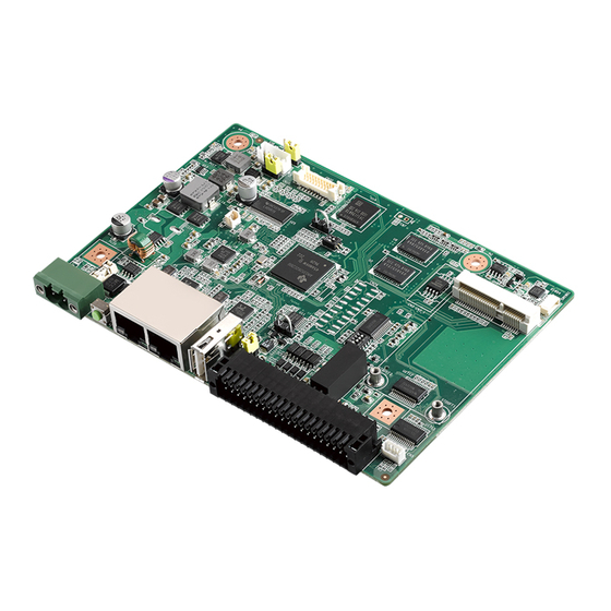
RSB-4220 is a 3.5” single-board computer (SBC) equipped with a TI Sitara AM3352 Cortex A8 1GHz processor. RSB-4220 supports 512 MB of DDR3, 4 GB of eMMC onboard flash, LVDS, 5 serial ports, 1 USB 2.0 client, 2 GbE, 1 SD, and 1 Mini PCIe port. -
Page 9: Mechanical Specifications
RGMII1 RJ45 UART1 MAX3243 RJ45 RTL8211E RGMII2 UART0 TI Sitara AM3352 1GHz UART2 MAX3243 MINI-PCIE SOCKET USB1 UART3 USB Host/OTG USB0 UART4 MAX3243 UART5 SD SOCKET 4bit SDIO I2C0 PCA9538 GPIO 4MB NOR FLASH SPI0 CAN0 SN65HVD232 RSB-4220 User Manual... - Page 10 RSB-4220 User Manual...
-
Page 11: Chapter 2 H/W Installation
Chapter H/W Installation This chapter explains the system hardware startup procedures, including jumper, switch, and indicator setting, as well as device integration. Mechanical drawings are also provided. Please read all safety precautions before beginning installation. -
Page 12: Jumpers
Warning! To avoid damaging the computer, always turn the power supply off before setting jumpers. 2.1.2 Jumper List Table 2.1: Jumper List Boot device (SW9) LVDS power (CN29) Backlight power (CN30) USB host/OTG (CN25) UART1 RS232, RS422, RS485 select (SW8) RSB-4220 User Manual... -
Page 13: Jumper Settings
Pin header 3x1P 2.54 mm 180D(M) DIP 205-1x3GS Setting Function (1-2) +3.3 V (2-3) LVDS backlight power (CN30) Part Number 1653003100 Footprint HD_3x1P_100_D Description Pin header 3x1P 2.54 mm 180D(M) DIP 205-1x3GS Setting Function (1-2) (2-3) +V12 RSB-4220 User Manual... - Page 14 USB OTG device UART1 RS232, RS422, RS485 select (SW8) Part number 1600000084 Footprint SW_4x2P_50_260x220 Description DIP SW CHS-02TB(29) SMD 4P SPST P = 1.27 mm W = 5.4 mm Setting Function (ON-ON-ON-OFF) RS232 (OFF-OFF-ON-OFF) RS422 (OFF-ON-OFF-ON) RS485 RSB-4220 User Manual...
-
Page 15: Connectors
2x20 pin terminal block 2.2.2 Connector Settings 2.2.2.1 RTC Battery Connector (CN1) RSB-4220 supports a lithium 3V/210 mAH CR2032 battery with wire via a battery connector. 2.2.2.2 Mini PCIe (CN2) RSB-4220 supports a full-size Mini PCIe slot with USB interface. For half-size Wi-Fi cards, users must purchase an extension bracket (P/N: 1960047454N000) to install the Wi-Fi card. -
Page 16: Figure 2.1 Mini Pcie
USB_D+ +3.3 V +3.3 V +3.3 V Figure 2.1 Mini PCIe RSB-4220 User Manual... -
Page 17: Figure 2.2 Debug Port
DEBUG_RXD Figure 2.2 Debug Port 2.2.2.4 USB Type-A Connector (CN12) RSB-4220 has one standard USB 2.0 type-A connector in the coastline. Users can connect either a USB host or OTG device via the jumper setting. Description +5 V USB data- USB data+ Figure 2.3 USB Type-A Connector... - Page 18 2.2.2.5 Ethernet Connector (CN36) RSB-4220 features 2 RJ45 LAN interface connectors, which are fully compliant with the IEEE 802.3u 10/100/1000 Base-T CSMA/CD standards. A standard RJ-45 jack connector links the Ethernet ports to the LED indicators at the front of the device that indicate the system speed and Active/Link status.
-
Page 19: Figure 2.4 Ethernet Connector
Figure 2.4 Ethernet Connector RSB-4220 User Manual... -
Page 20: Figure 2.5 Dc Power Jack
Description DC_IN Figure 2.5 DC Power Jack 2.2.2.7 Reset Button (SW3) RSB-4220 features a reset button located at the front of the device. Press this button to initiate the hardware reset function. Description RESET Figure 2.6 Reset Button RSB-4220 User Manual... -
Page 21: Figure 2.7 Sd Slot
2.2.2.8 SD Slot (SD1) RSB-4220based on TI AM335X datasheet complies with SD&SDIO specifications 2.0. Advantech used 4G SD for testing (SDHC). Signal Name DAT3 +3.3 V DAT0 DAT1 DAT2 Figure 2.7 SD Slot RSB-4220 User Manual... -
Page 22: Figure 2.8 Lvds Connector
2.2.2.9 LVDS Connector (CN32) RSB-4220 features an LVDS 10x2-pin board-to-board connector for a single-channel 18-bit LVDS panel (up to 1366 x 768). Please refer to the jumper settings provided on Page 16 before connecting the LVDS panel. Description LVDS0_z_D0+ SCL_LVDS0... -
Page 23: Figure 2.9 Lvds Inverter Power Connector
LCD_BKLT_PWM_A Figure 2.9 LVDS Inverter Power Connector 2.2.2.11 2x20-Pin Connector (CN28) RSB-4220 features a 2x20-pin connector, which comprises five 2-wire UARTs with TX/RX, a 4-wire UART that supports RS232/RS422/RS485, one 5V CAN, one I2C bus, and 4 GPI/GPO w/isolation. Description... -
Page 24: Figure 2.102X20-Pin Connector
COM5_TX COM1_RXD COM5_RX 422-485_TXD+ CAN1_D+ 422-485_TXD- CAN1_D- COM2_RX COM0_TX COM2_TX COM0_RX COM4_TX COM3_TX COM4_RX COM3_RX Figure 2.10 2x20-Pin Connector RSB-4220 User Manual... -
Page 25: Mechanical
Mini PCIe Jumper for USB host/OTG Debug Port DC_IN Reset LAN1 LAN0 USB 2 x 20 Pin Connector Figure 2.11 Jumper and Connector Layout (Top) SD Card Figure 2.12 Jumper and Connector Layout (Bottom) Figure 2.13 Coastline Layout RSB-4220 User Manual... -
Page 26: Board Dimensions
2.3.2 Board Dimensions 2.3.2.1 Board Drawings 7,11 8,00 12,50 25,91 26,02 28,55 30,73 38,32 50,24 59,29 71,94 78,49 81,92 107,18 111,00 127,89 129,05 140,72 146,00 Figure 2.14 Board Dimensions Layout (Top) RSB-4220 User Manual... -
Page 27: Figure 2.15Board Dimensions Layout (Bottom)
146,00 127,89 112,00 111,00 8,00 7,11 Figure 2.15 Board Dimensions Layout (Bottom) 107,18 16,30 71,94 15,40 43,25 10,10 28,55 8,80 10,00 12,30 Figure 2.16 Board Dimensions Layout (Coastline) RSB-4220 User Manual... -
Page 28: Quick Start
2-7. After the bootloader is programmed on the SD card, insert the power adapter connector into the DC jack on RSB-4220 to power up the board. The terminal screen will display the bootloader prompt. Figure 2.17 HyperTerminal Settings for Terminal Setup... -
Page 29: Test Tools
Test Tools All test tools must be verified on RSB-4220. Prepare all required test fixtures before verifying every specified I/O. Should problems obtaining test fixtures be encountered, please contact Advantech for assistance. 2.5.1 eMMC Test Check the NAND flash memory space. -
Page 30: Usb Test
Jump to OTG mode. Use a USB type-A cable to connect the USB-OTG port of RSB-4220 to the USB port of your PC. Copy the 20 MB xx file to RSB-4220 from your PC. Check that the RSB-4220 xx file size is 20 MB. -
Page 31: Spi Test
0000000 0000 0000 0000 0000 0000 0000 0000 0000 0001000 ============================================================ ################## --------------SPI mtdblock0 Write 0 PASS !!! ============================================================ ============================================================ ###################-----------> SPI Test all mtdblock0 PASS !!! ============================================================ ================================================ ############ Finish SPI all blocks Test PASS !!! ================================================ RSB-4220 User Manual... -
Page 32: I2C Test
70: -- -- -- UU -- -- -- -- =====I2C test Pass!===== 2.5.6 CAN Test Connect one RSB-4220 CAN port CAN1_D+ /CAN1_D- and GND to another RSB-4220 CAN port. Run program to transmit data between the two RSB-4220 CAN ports. root@am335x-adv:/unit_tests# ./AutoRun_CAN.sh... -
Page 33: Gpio Test
2.5.7 GPIO Test Power on RSB-4220 and boot into OS. Short GPI0 to GPO0, GPI1 to GPO1, GPI2 to GPO2, and GPI3 to GPO3. Run program to test GPIO read/write function. root@am335x-adv:/unit_tests# ./AutoRun_gpio.sh RSB-4220 GPIO200 direction is: GPIO201 direction is:... -
Page 34: Lan Test
RSB-4220 sets DHCP as the default network protocol. 2.5.9.1 Eth0 Test Connect the RSB-4220 eth0 port to a host computer. Configure the RSB-4220 eth0 port IP address as 192.168.1.2, and configure the host computer IP address as 192.168.1.1. root@am335x-adv:~# ifconfig eth0 192.168.1.2 root@am335x-adv:~# ifconfig eth0... - Page 35 2.5.9.2 Eth1 Test Connect the RSB-4220 eth1 port to a host computer. Configure the RSB-4220 eth1 port IP address as 192.168.1.3. root@am335x-adv:~# ifconfig eth1 192.168.1.3 root@am335x-adv:~# ifconfig eth1 eth1 Link encap: Ethernet HWaddr 78:A5:04:DD:E1:0C inet addr:192.168.1.3 Bcast:192.168.1.255 Mask:255.255.255.0 UP BROADCAST RUNNING MULTICAST MTU:1500 Metric:1...
-
Page 36: Rs232 Test
2.5.10 RS232 Test RSB-4220 supports 6 UARTs. Of these, /dev/ttyo0 is reserved for the debug port (RSB-4220 CN5), while the remaining UART ports can be assigned by the user. 2.5.10.1 UART1 to UART5 RS232 Test Switch SW8 to set UART1 to work with RS232, and the short TX with RX of UART1 to UART5. - Page 37 RS485 port of ADAM, then connect the UART4 port to the RS232 port of ADAM. Run program to transmit data between UART1 and UART4. RSB-4220’s RS485 does not support auto flow control; this must be controlled by a user app.
-
Page 38: Watchdog Timer Test
2.5.11 Watchdog Timer Test RSB-4220 features an external watchdog IC that uses TI msp430g2202 to reset the system when exceptions occur. The valid watchdog timeout value is between 1 and 5000 seconds, and the default timeout value is 60 seconds. -
Page 39: Software Functionality
Chapter Software Functionality This chapter details the Linux operating system installed on the RSB-4220 platform. -
Page 40: Introduction
Ubuntu 14.04 LTS on your host PC before beginning RSB-4220 evaluation/development. Package Contents Two Linux packages are offered for RSB-4220. One is a pre-built system image for system recovery, and the other is a source code package (BSP). 3.2.1 Pre-Built System Image The pre-built system image RSB-4220LIVxxxx_yyyy-mm-dd.tar.gz can be obtained... -
Page 41: Figure 3.1 Source Code Package Structure
This folder contains scripts for the system configuration and “scripts” automatic image compilation. → This folder contains source code owned by Advantech. “source” 3.2.2.1 Cross_compiler The cross compiler tool chain can be used to compile the zImage and related appli- cations (gcc version 4.9.3 20150413). -
Page 42: Figure 3.2 Image Ootfs
→ Provided for sample testing. Figure 3.2 Image\rootfs 3.2.2.5 Scripts Several scripts provided by Advantech can facilitate more rapid system configuration and image building. These are listed below. – setenv.sh → Script for rapidly setting up a development environment. - Page 43 Plenty of online documents, books, and magazines provide information regarding both Linux-specific and general UNIX issues. Various README files located in /source/ linux-4.1.6+gitAUTOINC+52c4aa7cdb- g52c4aa7/Documentation provide kernel-specified installations and notes for drivers. Refer to /source/linux-4.1.6+gitAUTOINC+52c4aa7cdb-g52c4aa7/Documentation/ 00-INDEX for a description of the purpose of each README/note. RSB-4220 User Manual...
-
Page 44: Setting Up A Development Environment
All instructions in this guide are based on a Ubuntu 14.04 LTS development environ- ment. Please install Ubuntu 14.04 LTS on your PC/NB in advance. After obtaining the RSB-4220 Linux source code package, refer to the following instructions to extract data to your development environment: Copy the “AM335XLBVxxxx_yyyy-mm-dd.bin”... -
Page 45: Build Instructions
This section provides instructions on how to build the u-boot and Linux kernel. 3.4.1 Build a U-Boot Image Advantech provides a script for building the u-boot rapidly. Users can build a u-boot image by following the steps below. Open “terminal” on Ubuntu 14.04 LTS. -
Page 46: Create Linux System Boot Media
#cd ./RSB-4220LIVxxxx_yyyy-mm-dd/scripts #./mksd-linux.sh /dev/sdb Type “y” (Copy files and wait until the process is marked as [Done].) Then, insert the Linux system SD card into RSB-4220 and the system will boot up into a Linux environment. 3.5.2.2 From a Source Code Package Using the RSB-4220 Linux source code package, follow the instructions below to cre- ate a Linux system SD card for boot up. -
Page 47: Boot From Onboard Flash
Now you can boot from onboard flash without an SD card. Debug Message RSB-4220 can be connected to a host PC (Linux or Windows) via a console cable and debug port adapter. To communicate with a host PC, a serial communication pro- gram, such as HyperTerminal, Tera Term, or PuTTY, is required. -
Page 48: Linux System Configuration And Use
= <&timing0>; timing2: 1360x768 { hactive = <1024>; vactive = <768>; hback-porch = <120>; hfront-porch = <120>; hsync-len = <104>; vback-porch = <20>; vfront-porch = <20>; vsync-len = <1>; clock-frequency = <60000000>; hsync-active = <0>; vsync-active = <0>; RSB-4220 User Manual... - Page 49 = <0>; timing2: 1360x768 { hactive = <1024>; vactive = <768>; hback-porch = <120>; hfront-porch = <120>; hsync-len = <104>; vback-porch = <20>; vfront-porch = <20>; vsync-len = <1>; clock-frequency = <60000000>; hsync-active = <0>; vsync-active = <0>; RSB-4220 User Manual...
-
Page 50: Service Configuration
TFTP server is /tftpboot. Users must execute “chmod 777 /tftpboot” on RSB-4220 to enable operation of the TFTP server. Then, users can communicate with RSB-4220 by TFTP via the TFTP client on the host PC. Use the command line to obtain and store files as follows: hostPC$ tftp TARGET_SYSTEM_IP tftp>get file1... - Page 51 3.7.2.2 FTP Server The ftp server on RSB-4220 is vsftpd and you should manually start it using flowing command: root@am335x-adv:/ # /etc/init.d/vsftpd start The service stop command is as follows: root@am335x-adv:/ # /etc/init.d/vsftpd stop Note! After activating the FTP server, manually add the user FTP.
-
Page 52: Network Configuration
3.7.4 Date/Time Configuration* Use the tool provided to modify the system time. Click on the “Time Settings” icon shown on screen to initiate Advantech’s Date/Time Settings utility. Figure 3.4 Date/Time Settings After adjusting the time, click “OK” to save all changes. RTC time will automatically synchronize to the time set. -
Page 53: Brightness Control
Figure 3.5 Brightness Control 3.7.7 Serial Tools The system is equipped with five serial ports, ttyO1, ttyO2, ttyO3, ttyO4, and ttyO5. A serial test tool is provided for validating the serial ports. Figure 3.6 Serial Control RSB-4220 User Manual... -
Page 54: Matrix Gui User Guide
To set Matrix to activate upon system boot up by default, run the following command on RSB-4220: advantech# ln -s /etc/init.d/matrix-gui-2.0 /etc/rc5.d/S97matrix-gui-2.0 To cancel the default startup, simply delete the S97matrix-gui-2.0 file. For more information on the use of Matrix, please refer to the following website: http://processors.wiki.ti.com/index.php/Matrix_Users_Guide... -
Page 55: Add Startup Items
/shutdown the basename will run automatically NN: 0~99 runlvl: RSB4220 runlevel is 5(default); eg. update-rc.d networking start 40 5 . (The “.” is also a parameter. If missing, the operation will be failed) then you can find S40networking in the rc5.d directory. RSB-4220 User Manual... -
Page 56: Otg Mode Selection
Compile helloworld.c using the following command: # $CC -o helloworld helloworld.c Hello world should be visible in the current directory.\ Run the helloworld executable file on RSB-4220. Insert the Linux system SD card into the development computer. # cp helloworld /media/rootfs/tool... -
Page 57: Developing Gui Programs With A Qt Library
Note! The Linux system SD card mounting point is /media/rootfs. Remove the SD card and insert it into RSB-4220, then open the serial console. On the RSB-4220 platform, type #root (Login) On the RSB-4220 platform, type #cd /tool On the RSB-4220 platform, type #./helloworld “Hello World!”... - Page 58 /*get the current timeout value the driver used*/ int timeout = 0; ioctl (fd, WDIOC_GETTIMEOUT, &timeout); Refer to the <BSP_PATH>/source/demo/watchdog folder for more information. 3.8.3.3 GPIO Programming RSB-4220 features eight GPIOs. Refer to <BSP_PATH>/source/demo/gpio Usage ./gpio_ctrl 200 out 1 RSB-4220 User Manual...
- Page 59 /sys/class/backlight/pwm-backlight/brightness Set the brightness value using the following command: # echo “3” > /sys/class/backlight/backlight/brightness Note! The value should be between 1-8. Obtain the current brightness value using the following command: # cat /sys/class/backlight/backlight/brightness RSB-4220 User Manual...
- Page 60 RSB-4220 User Manual...
-
Page 61: System Recovery
Chapter System Recovery This chapter explains how to recover a Linux operating system if accidentally damaged. -
Page 62: System Recovery
Ubuntu 14.04 LTS, and set the baud rate to 115200. For detailed console settings, refer to Section 3.6. On the RSB-4220 platform, type #root (login) On the RSB-4220 platform, type #cd /mk_inand On the RSB-4220 platform, type #./mkinand-linux.sh /dev/mmcblk1 On the RSB-4220 platform, type “y “... -
Page 63: Advantech Services
Chapter Advantech Services This chapter outlines Advantech’s design-in service, technical sup- port, and warranty policy for RSB- 4220. -
Page 64: Risc Design-In Services
Close interactive relationships with leading original manufacturers of CPUs and chip- sets, such as ARM, TI, and Freescale, enable Advantech to assist customers with solving communication and technical support difficulties, reducing the uncertainties of product development. Advantech’s professional software team also emphasizes the provision of a comprehensive BSP and assists customers in establishing a software development environment for their RISC platforms. - Page 65 RISC COM. Design stage When a product moves into the design stage, Advantech supplies a carrier board design guide for reference. The carrier board design guide contains pin definitions for the COM connector and explains the carrier board design limitations and recommen- dations, providing a clear guideline for customers to use when developing carrier boards.
-
Page 66: Contact Information
In its supportive capacity, Advantech primarily helps customers resolve problems related to testing and offers relevant tips and suggestions. By adopting an efficient verification process backed by our technical support, customers can easily optimize their applications. Furthermore, Advantech’s team offers professional consultation... -
Page 67: Global Service Policy
DOA cross-shipment excludes any shipping damage, customized, and/or built-to- order products. For products not declared DOA, customers are responsible for the cost of returning the product to an authorized Advantech repair facility. The cost of shipping replace- ment products to customers will be the responsibility of Advantech. 5.3.1.3... -
Page 68: Repair Process
Vague entries such as “does not work” and “failure” are not acceptable. If you are unsure of the cause of the problem, please contact Advantech’s application engineers (AE) who may be able to offer a solution that does not require sending the product for repair. - Page 69 Customer-requested updates and upgrades to products already out of warranty. If a product has been repaired by Advantech and then requires another repair for the same problem within three months of the initial repair, Advantech will perform the repair free of charge. However, such free repairs do not apply to products that have been misused, abused, or subjected to unauthorized disassembly/modification;...
- Page 70 Return Shipping to Customer The forwarding company selected to handle RMA returns from Advantech to custom- ers will be determined by Advantech. Other express services, such as UPS or FedEx, can be arranged upon request. The customer will be responsible for the extra cost incurred for alternative shipment.
- Page 71 RSB-4220 User Manual...
- Page 72 No part of this publication may be reproduced in any form or by any means, such as electronically, by photocopying, recording, or otherwise, without prior written permission from the publisher. All brand and product names are trademarks or registered trademarks of their respective companies. © Advantech Co., Ltd. 2017...
Need help?
Do you have a question about the RSB-4220 and is the answer not in the manual?
Questions and answers