
Related Manuals for gofanco HDExtIP4K


Summary of Contents for gofanco HDExtIP4K
- Page 1 HDMI IP Extender 4K - 120m User's Guide Part Number: HDExtIP4K (Kit) HDExtIP4K-TX (Transmitter) HDExtIP4K-RX (Receiver) G4-0071A...
- Page 2 Thank you for purchasing from gofanco. Our products aim to meet all your connectivity needs wherever you go. For optimum performance and safety, please read the instructions carefully and keep this User’s Guide for future reference. If you need more information about our products, please visit www.gofanco.com.
- Page 3 • Offers scalable matrix configuration through IGMP IP networks, up to 256 total units combined (maximum of 100 transmitter units allowed), additional transmitter units (part # HDExtIP4K-TX) and receiver units (part# HDExtIP4K-RX) sold separately • Supports up to 4K@60Hz resolution •...
-
Page 4: Product Layout
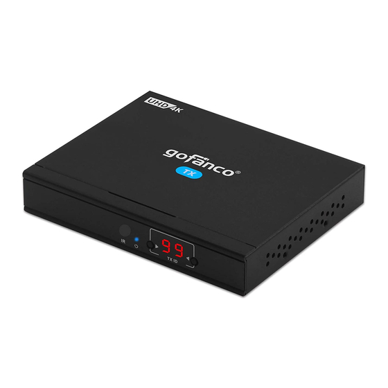
Installation Requirements HDMI source device (computer, DVD player, etc.) HDMI display device (SDTV/Monitor, HDTV/Monitor, projector, etc.) UTP/STP CAT5e/6 cable following IEEE-568B wiring standard Product Layout Figure 1: Transmitter (TX) Receives IR signals from the included remote 1. IR Window control to set/select the channel 2. - Page 5 Figure 2: Receiver (RX) 1. RX ID Displays the Receiver's ID number Receives IR signals from the included 2. IR Window remote control to set/select the channel 3. Power LED On when the Receiver is powered on Displays Transmitter's ID number for 4.
- Page 6 Hardware Installation CAT Cable Wiring We suggest both RJ-45 connectors be wired identically following T568B wiring standard for the best performance and compatiblity. One to One Configuration Power off all devices including your HDMI source and HDMI display(s). Connect your HDMI source device to the Transmitter's HDMI Input connector with an HDMI cable (HDMI cable not included).
- Page 7 Optional: Connect the IR Blaster Cable to the Transmitter's IR Output port. Face the eye towards your HDMI source device's IR window. This connection is needed only if you need to control your HDMI source from the remote location. Plug your CAT5e/6 cable between the Transmitter's RJ45 Output and Receiver's RJ45 Input.
- Page 8 Network Configuration Dedicated IGMP Gigabit Ethernet switches are recommended for the best performance and reliability. When connecting to an existing LAN environment, it's recommended to configure a VLAN dedicated to these transmitter(s) and receiver(s) to avoid traffic collision with other networking devices.
- Page 9 Optional: Connect a HDMI display to the Transmitter's HDMI out connector with an HDMI cable (HDMI cable not included) for local monitoring of the HDMI signal. Optional: Connect the IR Blaster Extension Cable to the Transmitter's IR output port. Face the eye towards your HDMI source device's IR window.
- Page 10 Connect your HDMI display to the Receiver's HDMI ouput connector with a HDMI cable (HDMI cable not included). Optional: Connect the IR Receiver Cable to the Receiver's IR Input port. This connection is needed only if you need to control your HDMI source device from the remote location.
- Page 11 Connection Diagram One to One Configuration Network Configuration Maximum 256 combined units, limited to 100 transmitter units.
- Page 12 Resetting to Default IP Address The Transmitter's default IP address is 192.168.1.238, the Receiver's default IP address is 192.168.1.239. If you need to reset the units to the default IP address simply disconnect the TX or RX unit from the IP network, then quickly press the Reset button.
- Page 13 IR User Guide IR Extension Cables The IR Blaster cable should be plugged into the IR Out port of the Transmitter and the IR Receiver cable should be plugged into the IR In port of the Receiver. The emitter of the IR Blaster cable should be placed as close to the IR receiver window of the source device.
- Page 14 Computer Control User Guide The HDbitT E-Matrix Control Center application is compatible with Windows only. Download it from www.hdbitt.com/download-matrix. Connect your Windows computer to the Ethernet network. For non-DHCP networks: Change your computer's IP address to 192.168.1.xxx (xxx can be 0 to 255, excluding 238 &...
- Page 15 Open the application downloaded earlier, the interface is displayed, see Figure 1. Figure 1 Note: If the Matrix Control Center appplication is not working properly. Close and restart it to clear the previous settings.
- Page 16 IP Setting The Transmitter's default IP address is 192.168.1.238, the Receiver's default IP address is 192.168.1.239. There is no need to change the IP address even when multiple transmitters and/ or receivers are connected to your IP network simultaneously. However, if a change is needed follow the steps below.
- Page 17 Device Name Use this section to change the device name. Click Start Scan to open the editing window, see Figure 3. Figure 3 Double click on a TX unit to update, then click OK to save the changes, see Figure 4. Figure 4...
- Page 18 Device ID Click on TX ID of the device you want to change, select an available ID from the drop down box, see Figure 5. Click Update to save the changes. Figure 5...
- Page 19 Operating Modes An operating mode is a group of input and output devices allowing easy selection of desired viewing outcome quickly and stress free. Click on Pre edit mode tab. Select the input and output IDs. Enter a name for the operating mode, then press OK to save.
- Page 20 Wireless Control APP Requires connecting a Wireless Router/Access point to the dedicated LAN. Download the "Matrix Control Lite" wireless APP for Android or Apple from www.hdbitt.com/download-matrix. Connect your DHCP enabled Wireless Router/Access point to your dedicated LAN. Log into your Wireless Router/Access point. Open the Matrix Control Lite App.
- Page 21 FAQ & Solutions If the extender is not working properly, please press the reset button on both the transmitter and receiver. Doing this will usually solve any problems. Q1: The TV displays "Waiting for connection": A1: 1) Please check the power supply of both transmitter and receiver is connected and powered on.
-
Page 22: Specifications
Specifications Item Specifications Compliance HDMI 2.0 & HDCP 2.2 256 units combined, limited to Matrix Configuration 100 Transmitters (TX) Network Bandwidth 18Gbps Protocol HDBitT Compression H.264 Latency <200ms Resolution 1080p@60Hz / 4K@60Hz Audio Support TMDS Signal 0.7 - 1.2Vp-p DDC Signal 5Vp-p(TTL) HDMI Cable Length 5 meters Input &... - Page 23 Disclaimer The product name and brand name may be registered trademarks of related manufacturers. TM and ® may be omitted on the user’s guide. The pictures on the user’s guide are just for reference, and there may be some slight differences with the actual products.
- Page 24 Thank you for choosing gofanco www.gofanco.com...
Need help?
Do you have a question about the HDExtIP4K and is the answer not in the manual?
Questions and answers