Advertisement
Quick Links
Advertisement

Related Manuals for gofanco HDExt24-HD20


Summary of Contents for gofanco HDExt24-HD20
- Page 1 2x4 HDMI 2.0 Splitter/Extender User's Guide P/N:HDExt24-HD20 G4-0112A...
-
Page 2: Important Safety Notices
Thank you for purchasing from gofanco. Our products aim to meet all your connectivity needs wherever you go. For optimum performance and safety, please read the instructions carefully and keep this User's Guide for future reference. If you need more information about our products, please visit www.gofanco.com. -
Page 3: Installation Requirements
Introduction The 2x4 HDMI 2.0 Splitter/Extender distributes HDMI signals from one of two source devices to 4 CAT6/7 outputs and one HDMI output (loopout). Features • Distributes HDMI signals from one of two inputs to 4 CAT6/7 outputs and one HDMI output (loopout) •... -
Page 4: Package Contents
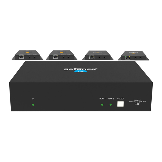
Package Contents 2x4 HDMI 2.0 Splitter/Extender • 1x 2x4 HDMI 2.0 Splitter/Extender • 4x Plastic cushions • 4x IR Receiver cables • 1x IR Emitter cable 1x RS232 Cable (3-pin to DB9) • • 1x IR cable (3.5mm (m) to 3.5mm (m)) used for IR cascade •... - Page 5 Product Layout Figure 1: 2x4 HDMI 2.0 Splitter/Extender Front Panel Layout Off: No power Power LED On: Splitter/Extender is powered on Blinking: Splitter/Extender is in standby mode On: HDMI input signal detected HDMI Input LED Flashing: HDMI input source not detected Press to switch to the next source device Press and hold for 3 seconds to switch between Select Button...
- Page 6 Figure 2: 2x4 HDMI 2.0 Splitter/Extender Rear Panel Layout HDMI Input (1-2) Connects to an HDMI source device HDMI/Loop Connects to a local HDMI display Connects to the Input of the CAT 6/7 Receivers. It supports PoC to power the receiver. The CAT 6/7 Out (1-4) orange LED illuminates when an HDMI signal is detected.
- Page 7 Figure 3: CAT 6/7 Receiver Front and Back Panel Layout HDMI Out Connects to an HDMI display Connects to the Splitter/Extender's CAT 6/7 outputs using a CAT cable. It supports PoC to power the CAT 6/7 Receiver over CAT cable CAT 6/7 In Orange LED: On when an HDMI signal is detected...
-
Page 8: Hardware Installation
Hardware Installation Power off all devices including your HDMI source(s) and HDMI display(s). Connect your HDMI source device(s) to the 2x4 HDMI 2.0 Splitter/Extender's HDMI Input connector(s) with HDMI cable(s) (HDMI cables not included). Connect your CAT cables between the Splitter/ Extender and CAT 6/7 Receivers. - Page 9 Application Diagram The application diagram shows the most typical input and output devices used with the Splitter/Extender. Figure 4: Application Diagram CAT Cable Wiring We suggest both RJ-45 connectors be wired identically using T568B wiring standard for the best performance and compatibility.
- Page 10 Source Device Switching Manual Switching Press the Select button to switch to the next source device, the corressponding input LED will light up. Auto Switching Press and hold down the Select button for at least 3 seconds to enable auto-switching mode. The operating parameters are shown below.
- Page 11 IR Control Provides IR control of the connected devices. The IR feature is bi-directional so either the source device or the display device(s) can be remotely controlled. Controlling the Source Device Connect an IR Emitter Cable to the IR Out port of the Splitter/Extender.
- Page 12 Controlling the Display Device(s) using IR In Allows you to remotely control each display individually. Connect an IR Receiver Cable to the IR In port of the Splitter/Extender. Connect an IR Emitter Cable to the IR Out port on each CAT 6/7 Receiver. Point the IR Emitter Cable's IR eye in line with the display's IR window.
- Page 13 Controlling the Display Device(s) using IR All In Port Allows remote controlling of all of the display devices simultaneously. Connect an IR Receiver Cable to the IR All In port of the Splitter/Extender. Connect an IR Emitter Cable to the IR Out port on each CAT 6/7 Receiver.
- Page 14 EDID Management EDID is used by the source device to match the video resolution to the connected display(s). The source device obtains its EDID from the 1st connected display as default setting. However, since displays with different capabilities are often connected to the Splitter/Extender, the EDID DIP switch can be used to set the EDID to a fixed value to offer the best compatiblity accross all connected displays.
- Page 15 Resolution Downscaling The Splitter/Extender supports 4K resolution downscaling for compatibility with 1080p display devices shown in the table below.
- Page 16 RS232 Control Connect the control PC's RS232 serial port to the Splitter/ Extender's RS232 port using the included RS232 cable. RS232 Control Software Works with most serial command and monitoring software such as CommWatch. • Download CommWatch or the serial command software of your choice •...
- Page 17 Control Software Interface Set the COM port, Baud rate, data bit, stop bit, and parity. Enter commands into the Command Sending Area.
- Page 18 RS232 Commands The splitter and compatible receivers features RS232 ports to transmit RS232 signals from computer to control far-end third-party devices by using 3-pin to DB9 cable and a RS232 control software, such as docklight. After installing the RS232 control software, please set the parameters of COM number, bound rate, data bit, stop bit and the parity bit correctly.
- Page 19 Signal Switching Commands Cont'd...
- Page 20 Signal Switching Commands Cont'd CEC Commands...
- Page 21 CEC Commands Cont'd...
- Page 22 CEC Commands Cont'd...
- Page 23 FAQ & Troubleshooting Poor video quality or no video signal on display: A1: Check whether the HDMI cables are connected properly and are in good working condition. A2: Make sure the resolution of the display is compatible with the splitter's resolution No HDMI signal output from the CAT 6/7 connectors while the local HDMI out port is working normally:...
-
Page 24: Specifications
Specifications 2x4 HDMI 2.0 Splitter/Extender... - Page 25 2x4 HDMI 2.0 Splitter/Extender Cont'd CAT 6/7 Receiver...
- Page 26 CAT 6/7 Receiver Cont'd...
- Page 27 Disclaimer The product name and brand name may be registered trademarks of related manufacturers. TM and ® may be omitted on the user's guide. The pictures on the user's guide are just for reference, and there may be some slight differences with the actual products.
- Page 28 Thank you for choosing gofanco www.gofanco.com...
Need help?
Do you have a question about the HDExt24-HD20 and is the answer not in the manual?
Questions and answers