Emerson FloBoss 107 Instruction Manual
Flow manager
Hide thumbs
Also See for FloBoss 107:
- User manual (64 pages) ,
- Instruction manual (152 pages) ,
- Site considerations for equipment installation, grounding, and wiring manual (42 pages)

Related Manuals for Emerson FloBoss 107


Summary of Contents for Emerson FloBoss 107
- Page 1 Form Number A6206 Part Number D301232X012 February 2007 FloBoss 107 Flow Manager Instruction Manual Remote Automation Solutions...
- Page 2 ROCLINK and FloBoss are trademarks of one of the Emerson Process Management companies. The Emerson logo is a trademark and service mark of Emerson Electric Co. All other marks are the property of their respective owners. © 2007 Remote Automation Solutions, division of Emerson Process Management. All rights reserved.
-
Page 3: Table Of Contents
Environmental Requirements ................2-1 2.1.2 Site Requirements....................2-2 2.1.3 Compliance with Hazardous Area Standards ............ 2-4 Power Installation Requirements..................2-5 Grounding Installation Requirements ................2-5 2.3.1 Installing Grounding for the FloBoss 107 ............2-6 2.3.2 I/O Wiring Requirements ..................2-7 Issued Feb-07 Contents... - Page 4 Installing the FloBoss 107 and Expansion Rack .............. 2-7 2.4.1 Required Tools ....................2-7 2.4.2 Installing the FloBoss 107 without an Expansion Rack ........2-8 2.4.3 Installing the FloBoss with an Expansion Rack..........2-9 2.4.4 Removing an Expansion Rack ................. 2-11 2.4.5...
- Page 5 Chapter 6 – Multi-Variable Sensor (MVS) MVS Overview ........................6-1 Installing/Removing an MVS Module ................6-3 Configuring a Multi-drop MVS Module Setup ..............6-3 MVS Lightning Protection ....................6-5 Chapter 7 – Troubleshooting General Guidelines......................7-1 Graphical User Interface (GUI)..................7-2 Checklists .........................
- Page 6 Contents Issued Feb-07...
-
Page 7: Chapter 1 - General Information
This manual describes the FloBoss 107 Flow Manager (“FB107”), part of the family of FloBoss flow computers manufactured by Remote Automation Solutions, a division of Emerson Process Management. For information about the software you use to configure the FB107, refer to ™... -
Page 8: Scope Of Manual
FloBoss 107 Instruction Manual 1.1 Scope of Manual This manual contains the following chapters: Chapter 1 Provides an overview of the hardware and firmware General Information for the FB107 base unit and the expansion rack. Chapter 2 Provides information on installation, tools, wiring, Installation and Use and other essential elements of the FB107. - Page 9 COM CPU I/O module Assembly (COM2) Slot 1 = I/O, MVS, or COM module (COM3) Wire Channel Cover Input Power Display Connector Connector Dual-Variable Memory Backup Sensor Connector Battery Connector Figure 1-1. FloBoss 107 Base Unit Issued Feb-07 General Information...
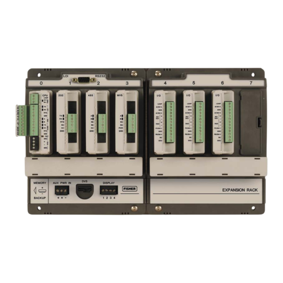
- Page 10 Slot 4 = I/O or MVS module MVS module Slot 5 = I/O or Slot 6 = I/O or MVS module MVS module Wire Channel Cover Connects to FloBoss 107 base unit Figure 1-2. FloBoss 107 Expansion Rack General Information Issued Feb-07...
-
Page 11: Hardware
FloBoss 107 Instruction Manual Figure 1-3. FloBoss 107 with Expansion Rack The FB107 provides the following components and features: 32-bit processor board, inter-connect board, and backplane board. Central processing unit (CPU). Field upgradeable 2 MB flash ROM (read only memory). -
Page 12: Processor And Memory
FloBoss 107 Instruction Manual Isolation occurs between the CPU and the field logic. Note: The FB107 base unit has four slots. Slot 0 is reserved for the CPU module, which provides three communication ports, an RTD, power input, loop power output, system variables, and optional 6 points of I/O. - Page 13 FloBoss 107 Instruction Manual Automatic self-tests. Power saving modes. Local operator interface (LOI) EIA-232 (RS-232). EIA-485 (RS-485) communications (COM1). EIA-232 (RS-232) communications (COM2). Boot Flash – System initialization and diagnostics. SRAM (static random access memory) with battery backup – Data logs and configuration.
-
Page 14: Battery And Super-Capacitor
FloBoss 107 Instruction Manual 1.3.5 Battery and Super-capacitor A super capacitor (“super-cap”) and a coin type battery work together to provide backup power for the static RAM and the real-time clock. This helps to ensure retention of short and longer-term data, configuration, and operational integrity when the FB107 is not in service or is in storage. - Page 15 FloBoss 107 Instruction Manual The LOI supports ROC or Modbus slave protocol communications. The LOI also supports the log-on security feature of the FB107, if you enable the security on LOI using ROCLINK 800. Default values for the LOI port are: 19,200 baud rate, 8 data bits, 1 stop bit, no parity, group 1, and address 2.
-
Page 16: Built-In Resistance Thermal Device (Rtd)
FloBoss 107 Instruction Manual 1.3.8 Built-in Resistance Thermal Device (RTD) The FB107 supports a direct input from a resistance thermal device (RTD) sensor to measure flowing temperature. An RTD temperature probe typically mounts in a thermowell on the meter run. The RTD has a measurement range of −40 to 400°C (−40 to 752°F). -
Page 17: Optional Communication Module - Com3
FloBoss 107 Instruction Manual I/O modules and one CPU I/O assembly, and can have up to 42 points of I/O. You can install I/O modules in slots 1 through 3 on the FB107 base unit and in slots 4 through 6 on the expansion rack. If you install a... -
Page 18: Optional License Key
FloBoss 107 Instruction Manual The MVS module provides current-limited power and EIA-485 (RS- 485) communications to external remote MVS transmitters. The FB107 supports six remote transmitters with up to four meter runs. 1.3.13 Optional License Key The optional application license key provides extended functionality, such as the use of various user programs. -
Page 19: History Points
FloBoss 107 Instruction Manual Applications requiring flow computation. Logic and sequencing control using a user-defined Function Sequence Table (FST). Closed-loop (PID) control capabilities (requires optional I/O module or CPU I/O assembly). Custom User C application support. Real-Time Operating The FB107 firmware uses a pre-emptive, multi-tasking, message-based System (RTOS) real-time operating system (RTOS). - Page 20 FloBoss 107 Instruction Manual memory that it requires for the configured number of points. Extended History only receives the surplus memory not used by the Standard History. Standard History archival properties include: Up to 100 points of minute data from the last 60 minutes.
-
Page 21: Alarm Log
FloBoss 107 Instruction Manual 1.4.2 Alarm Log The alarm log contains the change in the state of any alarm signal that has been enabled for alarms. The system alarm log has the capacity to maintain and store up to 240 alarms in a “circular” log. The alarm log... -
Page 22: Security
FloBoss 107 Instruction Manual The FB107 has the ability to limit the AGA calculation-related events to only critical events. Selecting Enabled in the Limit Meter Events field on the Meter Setup’s Advanced tab (Meter > Setup) keeps the system from filling the event log with unnecessary events. The events not logged include temperature, pressure, Reynolds number, and warnings for orifice diameter, pipe diameter, and beta ratio. -
Page 23: Spontaneous-Report-By-Exception (Srbx) Alarming
FloBoss 107 Instruction Manual device, such as a control valve. The FB107 supports eight PID control loops and requires an optional CPU I/O assembly or I/O module. The firmware sets up an independent PID algorithm (loop) in the FB107. The PID loop has its own user-defined input, output, and override capability. -
Page 24: Pass Through Communications
FloBoss 107 Instruction Manual 1.4.11 Pass Through Communications By using the FB107 communications ports, Pass Through Communications mode allows one unit to receive data and then pass it through to other devices connected on any other communications port. For example, the host communicates via a radio on the FB107 COM2 port. -
Page 25: Roclink 800 Configuration Software
FloBoss 107 Instruction Manual Communications programs. Special applications. You can transfer licenses for User C programs to the FB107 using ROCLINK 800’s License Key Administrator function (Utilities > License Key Administrator). ROCLINK 800 Configuration Software ® ® ROCLINK 800 Configuration software is a Microsoft... -
Page 26: Product Electronics
FloBoss 107 Instruction Manual daily history logs, and other history logs associated with the meter runs in the FB107. This file then becomes the custody transfer audit trail. Use ROCLINK 800 to: Configure and view input/output (I/O) points, flow calculations, meter runs, PID control loops, system parameters, and power management features. -
Page 27: Automatic Self Tests
For information on configuring alarms and System AI points, refer to Chapter 7 in the ROCLINK 800 Configuration Software User Manual (for FloBoss 107) (Form A6217). 1.6.3 Automatic Self Tests The FB107 becomes active when input power with the proper polarity and startup voltage (typically set greater than 8.0 volts) is applied to the... - Page 28 FloBoss 107 Instruction Manual AGA7 – Pulse (ISO 9951) for gas. AGA8 – Compressibility for Detailed (ISO 12213-2), Gross I (ISO 12213-3), and Gross II for gas. ISO 5167 – Differential. FB107 firmware completes full calculations every second on the configured meter run (up to four) for AGA3, AGA7, AGA8, and ISO 5167.
-
Page 29: Additional Information
Additional Information Refer to the following documents for additional information: Table 1-2. Additional Information Name Form Number Part Number ROCLINK 800 Configuration Software User Manual (for FloBoss 107) A6217 D301249X012 FloBoss 107 Flow Manager and Expansion Rack 5:FB107 D301233X012 FloBoss 107 Firmware 5.2:FW1... - Page 30 FloBoss 107 Instruction Manual 1-24 General Information Issued Feb-07...
-
Page 31: Chapter 2 - Installation And Use
Power Installation Requirements ............2-5 Grounding Installation Requirements ..........2-5 2.3.1 Installing Grounding for the FloBoss 107 ......2-6 2.3.2 I/O Wiring Requirements ............2-7 Installing the FloBoss 107 and Expansion Rack ........2-7 2.4.1 Required Tools ..............2-7 2.4.2 Installing the FloBoss 107 without an Expansion Rack..2-8 2.4.3 Installing the FloBoss with an Expansion Rack .....2-9... -
Page 32: Site Requirements
FloBoss 107 Instruction Manual : In salt spray environments, it is especially important to ensure Note that the enclosure, including all entry and exit points, is sealed properly. The FB107 is designed to operate over a −40 to 75°C (−40 to 167°F) temperature range. - Page 33 FloBoss 107 Instruction Manual Figure 2-1. Side and Front View of FloBoss 107 Base Unit Issued Fed-07 Installation and Use...
-
Page 34: Compliance With Hazardous Area Standards
FloBoss 107 Instruction Manual Figure 2-2. FloBoss 107 and Expansion Rack 2.1.3 Compliance with Hazardous Area Standards The FB107 has approval for Class I Division 2 Groups A, B, C and D. Class, Division, and Group are defined as: Class defines the general nature of the hazardous material in the surrounding atmosphere. -
Page 35: Power Installation Requirements
FloBoss 107 Instruction Manual o Group B – Atmosphere containing hydrogen, gases, or vapors of equivalent hazards. o Group C – Atmosphere containing ethylene, gases, or vapors of equivalent hazards. o Group D – Atmosphere containing propane, gases, or vapors of equivalent hazards. -
Page 36: Installing Grounding For The Floboss 107
The twisted pair and the shielding minimize signal errors caused by EMI (electromagnetic interference), RFI (radio frequency interference), and transients. 2.3.1 Installing Grounding for the FloBoss 107 If your company has no specific grounding requirements, install the FB107 as a floating system (unconnected to ground). Otherwise, follow your company’s specific grounding practices. -
Page 37: I/O Wiring Requirements
Use insulated, shielded, twisted-pair wiring when using MVS signal lines. The terminal block accepts wires up to size 16 to 24 AWG. Installing the FloBoss 107 and Expansion Rack This section details how to install the FB107 base unit and the expansion rack. -
Page 38: Installing The Floboss 107 Without An Expansion Rack
FloBoss 107 Instruction Manual 2.4.2 Installing the FloBoss 107 without an Expansion Rack To install the FB107 base unit without the expansion rack: Using the four holes on the FB107 base unit, mark the points at which the base unit should attach to the wall (refer to Figure 2-1). -
Page 39: Installing The Floboss With An Expansion Rack
FloBoss 107 Instruction Manual 2.4.3 Installing the FloBoss with an Expansion Rack The expansion rack has connectors for the I/O, MVS, and smart application modules. Do not remove the backplane from the housing. The backplane does not contain any field-serviceable parts. If the backplane requires maintenance, please contact your local sales representative. - Page 40 FloBoss 107 Instruction Manual Attachment posts Retaining clips Figure 2-4. Adapter Plate (FB107 Expansion Rack) To install the base unit and expansion rack to the FS1-ADP2 adapter plate: Place the unpowered FB107 base unit on the left side of the adapter plate so that the attachment posts touch the right-most inside of the plastic housing.
-
Page 41: Removing An Expansion Rack
FloBoss 107 Instruction Manual Secure the adapter plate to the wall using four 1 inch screws. : Adding an expansion rack and the modules may require you to Note adjust your FB107 power consumption requirements. Refer to Chapter 3, Determining Power Consumption. -
Page 42: Removing And Installing Wire Channel Covers
FloBoss 107 Instruction Manual : If you remove a module for an extended period, install a slot Note cover over the empty module slot to prevent dust and other matter from getting into the FB107. To install a module slot cover: Place the slot cover over the empty slot. -
Page 43: Removing And Installing The Battery
FloBoss 107 Instruction Manual 2.5.1 Removing and Installing the Battery To remove the battery on the backplane: Remove power from the FB107. Memory backup Figure 2-5. Memory Backup Cap Slide the Memory Backup cover to the left. Remove the battery by gently prying the battery from its terminals. -
Page 44: Removing The Cpu Module
FloBoss 107 Instruction Manual The CPU contains the firmware, the three built-in communication ports and LEDs, a reset (RST) switch, RTD input, and a power LED indicating system integrity. The internal super-cap backup battery provides backup of data and the real-time clock when the main power is not connected. -
Page 45: Installing The Cpu Module
FloBoss 107 Instruction Manual Remove all wiring from the CPU. Place your fingers on the ridged edges on both sides of the CPU module and pull gently (see Figure 2-7). The cover should slide forward and stop, releasing the module lock. -
Page 46: License Keys
FloBoss 107 Instruction Manual Review Restarting and Reconfiguring the FB107 in Chapter 7, Troubleshooting. Return power to the FB107. License Keys License keys with valid license codes grant access to applications or allow optional firmware functionality to execute. A license key may also be required before you can run the application. -
Page 47: Operation
Once startup is successful, it is necessary to configure the FB107 to meet the requirements of the application. Refer to the ROCLINK 800 Configuration Software User Manual (for FloBoss 107) (Form A6217) for procedures on configuring the FB107 and calibrating its I/O. Once you configure and calibrate the FB107, you can place it in operation. - Page 48 FloBoss 107 Instruction Manual 2-18 Installation and Use Issued Feb-07...
-
Page 49: Chapter 3 - Power Connections
FloBoss 107 Instruction Manual Chapter 3 – Power Connections This chapter describes wiring power from a dc voltage source. In This Chapter Power Input Descriptions..............3-1 Determining Power Consumption ............3-3 Wiring Connections................3-8 Wiring Power to the CPU Module ............3-9 Power Input Descriptions The FB107’s power terminals (either through the AUX PWR IN... - Page 50 FloBoss 107 Instruction Manual to all local and National Electrical Code (NEC) requirements for power installations. Power A dc voltage source is the typical source of primary power for FB107 Requirements installations. The FB107 accepts input voltages from 8.0 volts to 30 volts either at the AUX PWR IN connection on the base unit or at the PWR (IN+ / IN−) terminals on the CPU.
- Page 51 FloBoss 107 Instruction Manual Determining Power Consumption Use Tables 3-2 and 3-3 to identify and assess the power requirements for each component of your system. If the power input is not sufficient, you require an alternative power supply for external device or you need to lessen power demands.
- Page 52 FloBoss 107 Instruction Manual Line 5 − Select if you are using a EIA-232 (RS-232) communications module in Table 3-2. Calc Power (mW) equals: No EIA-232 (RS-232) communications module = 0 One EIA-232 (RS-232) communications module used = 36 Line 6 − Select if you are using a EIA-485 (RS-485) communications module in Table 3-2.
- Page 53 FloBoss 107 Instruction Manual Table 3-2. Estimated Power Consumption Line Nominal System Power Input 12 or 24 Volts dc Input Nominal Calc Duty Quantity Voltage Current Power Cycle (Volts dc) (mA) (mW) Non-Isolated 0 or 1 100% Base Unit including...
- Page 54 FloBoss 107 Instruction Manual Table 3-3. Field Side Power Consumption Nominal Input Voltage Calc Power Field Side Quantity Current Duty Cycle (Volts dc) (mW) (mA) Current Loops Field Transmitters Communications Radio Stand-By Display Additional Equipment Watts = mW ÷ 1000...
- Page 55 FloBoss 107 Instruction Manual Table 3-4. Power Consumption Example Line Nominal System Power Input Volts dc Input Nominal Calc Duty Quantity Voltage Current Power Cycle (Volts dc) (mA) (mW) Non-Isolated 100% Base Unit including CPU and Backplane Isolated 100% −...
-
Page 56: Wiring Connections
FloBoss 107 Instruction Manual Wiring Connections This section describes how to connect the FB107 to power, I/O devices, and communications devices. Use the recommendations and procedures described in this section to avoid damage to equipment. Check the input power polarity before you apply the power. -
Page 57: Wiring Power To The Cpu Module
FloBoss 107 Instruction Manual Wiring Power to the CPU Module Typically, you would use the AUX PWR IN connection on the FB107 base unit to power the FB107. Alternately, you can wire power directly into the CPU module. Power In + Power In –... - Page 58 FloBoss 107 Instruction Manual 3-10 Power Connections Issued Feb-07...
-
Page 59: Chapter 4 - Inputs/Outputs And Rtd Inputs
FloBoss 107 Instruction Manual Chapter 4 – Inputs/Outputs and RTD Inputs This chapter describes the input/output (I/O) termination points available on the CPU module’s optional I/O assembly and on the I/O modules. I/O points provide additional inputs and outputs for implementing expanded monitoring and control applications. - Page 60 FloBoss 107 Instruction Manual Using ROCLINK 800, you can select and configure five of the six points of I/O. Use ROCLINK 800 to select the inputs and outputs on the I/O Setup screen. You can add an expansion rack to the FB107 to increase I/O by four slots for a total of six slots of I/O.
- Page 61 FloBoss 107 Instruction Manual Loop Output Power AI1+/DI1+ GND – (Common) AI2+/DI2+ AO+/DO1+ AO–/DO1– DO2+ DO2– PI1+/DI3+ GND – (Common) PI2+/DI4+ NC (No Connection) GND – (Common) Figure 4-1. I/O Module Table 4-1. I/O Terminations on the I/O Modules Termination...
- Page 62 FloBoss 107 Instruction Manual AI1+/DI1+ GND – (Common) AI2+/DI2+ AO+/DO1+ AO–/DO1– DO2+ DO2– PI1+/DI3+ GND – (Common) PI2+/DI4+ Figure 4-2. CPU Module’s Optional I/O Assembly Table 4-2. I/O Terminations on the CPU Module’s Optional I/O Assembly Termination I/O Type Number AI1+/DI1+ GND –...
-
Page 63: Installing A Module
FloBoss 107 Instruction Manual Installing a Module All FB107 modules for the FB107 are designed for ease of installation and removal. They contain no user-serviceable components. Note: A tab on the module case prevents you from installing the module incorrectly. -
Page 64: Removing A Module
FloBoss 107 Instruction Manual Removing a Module To remove an I/O module: Remove power from the FB107. Remove the wiring (or the removable terminal blocks) from the module. Place your fingers on the ridged edges on both sides of the module and pull out gently (see Figure 4-3). -
Page 65: Selecting The Type Of I/O
FloBoss 107 Instruction Manual To connect the wire to the removable block compression terminals: Strip ¼ inch of insulation from the wire. Insert the bare end into the clamp beneath the termination screw. Tighten the screw, taking care not to over-torque it. - Page 66 FloBoss 107 Instruction Manual Figure 4-4. FloBoss 107 ROCLINK 800 User Interface Click the I/O Setup tab. Figure 4-5. I/O Setup Select the types of I/O to use. Inputs/Outputs and RTD Input Issued Feb-07...
-
Page 67: Analog Inputs (Ai)
FloBoss 107 Instruction Manual If you select analog inputs (AI), select the 250 Ohm Resistor Installed option if you want the analog input in the current loop mode. Click Apply. Make sure you select the I/O types before you configure the I/O Note: using ROCLINK 800. - Page 68 FloBoss 107 Instruction Manual 14 volts dc and you select a 10-volt loop, the loop output equals 14 volts dc. The I/O module only supports 24 volts dc loop output power. The CPU module’s I/O assembly uses the CPU’s loop power output and ground connections.
-
Page 69: Analog Outputs (Ao)
FloBoss 107 Instruction Manual INTERNALLY POWERED Figure 4-7. Loop Output Power for the I/O Module Analog Outputs (AO) The analog outputs (AO) provide a 4 to 20 mA current source output for powering analog loop devices. Analog outputs are analog signals the FB107 generates to regulate equipment, such as control valves or any device requiring analog control. -
Page 70: Discrete Inputs (Di)
FloBoss 107 Instruction Manual INTERNALLY POWERED Figure 4-8. Analog Output Wiring Discrete Inputs (DI) The discrete input (DI) monitors the status of relays, open collector/open drain type solid-state switches, and other two-state devices. Discrete inputs come from relays, switches, and other devices, which generate an on/off, open/close, or high/low signal. -
Page 71: Wiring The Discrete Inputs
FloBoss 107 Instruction Manual Select DI as the I/O Type for the selectable pulse inputs/discrete Note: inputs when you configure it for use as a discrete input. Refer to Figure 4-5. 4.8.1 Wiring the Discrete Inputs The terminals for connecting the DI wiring are shown in Figure 4-9. -
Page 72: Wiring The Discrete Outputs
FloBoss 107 Instruction Manual A discrete output may be set to send a pulse to a specified device. Discrete outputs are high and low outputs used to turn equipment on and off. The DO circuitry is optically coupled to help isolate the processor board from the input signal. -
Page 73: Pulse Inputs (Pi)
FloBoss 107 Instruction Manual INTERNAL CONTROL Figure 4-10. Discrete Outputs 4.10 Pulse Inputs (PI) Pulse inputs (PI) processes signals from pulse-generating devices and provide a calculated rate or an accumulated total over a configured period. The FB107 pulse input circuits are physically the same as the discrete inputs. -
Page 74: Wiring The Pulse Inputs
FloBoss 107 Instruction Manual 4.10.1 Wiring the Pulse Inputs Figure 4-11 shows the terminals for connecting the PI wiring. The + terminal is a positive source voltage; the GND terminal is the signal return. To use the channel as a pulse input, connect the + and GND field wires to terminals PI1+ or PI2+ and GND. -
Page 75: Wiring The Rtd Input
FloBoss 107 Instruction Manual The RTD input draws power for the active circuitry from lines on the backplane. It may be more convenient to perform calibration before connecting the field wiring. However, if the field wiring between the FB107 and the RTD probe is long enough to add a significant resistance, then perform calibration in a manner that considers this. - Page 76 FloBoss 107 Instruction Manual WHITE Jumper WHITE WHITE Figure 4-12. RTD Sensor Wiring 4-18 Inputs/Outputs and RTD Input Issued Feb-07...
-
Page 77: Chapter 5 - Communications
FloBoss 107 Instruction Manual Chapter 5 – Communications The FB107 communicates to external devices through its local operator interface port (LOI), the COM1 EIA-485 (RS-485) port, the COM2 EIA-232 (RS-232 port), or optionally on COM3 using a communications module. The communication terminals and communications modules provide communications between the FB107 and a host system or external devices. - Page 78 FloBoss 107 Instruction Manual Figure 5-1. EIA-232 (RS-232) Communications Figure 5-2. EIA-485 (RS-485) Communications Module Module LOI − Local Port EIA-232 (RS-232) COM1 − EIA-485 (RS-485) COM2 − Default EIA-232 (RS-232) Figure 5-3. CPU Communications Issued Feb-07...
- Page 79 FloBoss 107 Instruction Manual The FB107 supports up to four communication ports including: Local Operator Interface (RS-232C) – LOI for asynchronous serial communications, with DB9 connector. Defaults for the LOI are 19,200 baud rate, 8 data bits, no parity, and 1 stop bit.
-
Page 80: Installing/Removing A Communications Module
FloBoss 107 Instruction Manual LEDs display the A (transmit/receive+) and B (transmit/receive −) signals for EIA-485 (RS-485) communications. The FB107 has the capability to communicate with other devices using ROC or Modbus protocols. The firmware can automatically detect the two protocols (ROC or Modbus) at baud rates of up to 115.2 Kbps. -
Page 81: Wiring The Local Operator Interface (Loi) Port
FloBoss 107 Instruction Manual Wiring the Local Operator Interface (LOI) Port The Local Operator Interface (LOI) port provides a direct, local link between the FB107 and a PC through an optional Local Operator Interface Cable using EIA-232 (RS-232C) communications. You can purchase an LOI cable from your sales representative. -
Page 82: Wiring Eia-485 (Rs-485) Communications
FloBoss 107 Instruction Manual Configure communications for the other built-in and modular communications, I/O modules, AGA meter parameters, and other configuration parameters. Wiring EIA-485 (RS-485) Communications The EIA-485 communications provides for RS-485 signals on: COM1 port located on the CPU (labeled 485). -
Page 83: Wiring Eia-232 (Rs-232) Communications
FloBoss 107 Instruction Manual Table 5-2. EIA-485 (RS-485) Field Wiring Terminals Label Definition Transmit / Receive + Transmit / Receive − No connection (comm module only) No connection (comm module only) No connection (comm module only) Ground (common) Wiring EIA-232 (RS-232) Communications... -
Page 84: Wiring The Liquid Crystal Display (Lcd)
FloBoss 107 Instruction Manual Table 5-3. EIA-232 (RS-232) Field Wiring Terminals Label Definition Transmit data signals that data is being transmitted from the comm port Receive data signals that data is being received at the comm port Ready to Send signals that the port is ready to transmit... -
Page 85: Chapter 6 - Multi-Variable Sensor (Mvs)
FloBoss 107 Instruction Manual Chapter 6 – Multi-Variable Sensor (MVS) The Multi-Variable Sensor (MVS) module provides differential pressure, static pressure, and temperature inputs to the FB107 for orifice flow calculation. In This Chapter MVS Overview ..................6-1 Installing/Removing an MVS Module..........6-3 Configuring a Multi-drop MVS Module Setup ........6-3... - Page 86 FloBoss 107 Instruction Manual MVS modules have removable terminal blocks for convenient wiring and servicing. The terminal blocks can accommodate size 16 to 24 AWG. The FB107 scans each MVS transmitter once every second, accessing values for differential pressure, static pressure, and temperature as inputs for flow calculations, history, calibration, and alarming.
-
Page 87: Installing/Removing An Mvs Module
FloBoss 107 Instruction Manual The MVS consists of a transducer and an interface circuit. The transducer, contained in the sensor body, uses capacitance-cell technology to sense differential pressure and piezo-resistive technology to sense the static (absolute or gauge) pressure. The transducer electronics convert the pressure variables directly into a digital format, allowing accurate correction and compensation. - Page 88 FloBoss 107 Instruction Manual When installing units in a hazardous area, make sure all installation Caution components selected are labeled for use in such areas. Installation and maintenance must be performed only when the area is known to be non-hazardous. Installation in a hazardous area could result in personal injury or property damage.
-
Page 89: Mvs Lightning Protection
FloBoss 107 Instruction Manual All MVS units are sent from the factory with a default Note: interface address of 1. This allows you to accomplish first-time communications. Once you set a unique address for each MVS in the multi-drop configuration, connect like terminals to like (that is, electrically connect all the “A”... - Page 90 FloBoss 107 Instruction Manual These units are available from: Lightning Protection Corporation PO Box 6086 Santa Barbara, CA 93160 Telephone: 1-800-317-4043 http://www.lightningprotectioncor.com/ Multi-Variable Sensor (MVS) Issued Feb-07...
-
Page 91: Chapter 7 - Troubleshooting
FloBoss 107 Instruction Manual Chapter 7 – Troubleshooting This chapter provides generalized guidelines for troubleshooting the FB107. Perform the procedures in this chapter before removing power for any reason, after you restore power, and if you disassemble the FB107. The following tools are required for troubleshooting: IBM-compatible personal computer. -
Page 92: Graphical User Interface (Gui)
FloBoss 107 Instruction Manual When you finish troubleshooting, perform the restart procedure in Section 7.4.2, Restarting and Reconfiguring the FB107. Failure to exercise proper electrostatic discharge precautions, such Caution as wearing a grounded wrist strap may reset the processor or damage electronic components, resulting in interrupted operations. -
Page 93: Checklists
Integrity alerts are typically related to hardware. Alarms are typically related to user-defined configurations. For more information on the FB107 GUI, refer to the ROCLINK 800 Configuration Software User Manual (for FloBoss 107) (Form A6217). Checklists This section provides brief topical checklists. -
Page 94: Inputs/Outputs
FloBoss 107 Instruction Manual Verify the wiring connections at TX, RX, A, B, and GND. Refer to Chapter 5, Communications. : The Power In+ LED should be the only LED always on. All Note other LEDs flash only during communication. -
Page 95: Preserving Configuration And Log Data
FloBoss 107 Instruction Manual Notes FB107 modules do not contain any user-serviceable parts. You must perform a power restart to allow ROCLINK 800 to identify the module. 7.3.4 Preserving Configuration and Log Data Before you power down the FB107 to repair or upgrade, to remove or add a component, or to troubleshoot, you should preserve the FB107 configuration and log data held in RAM. -
Page 96: Powering Up
FloBoss 107 Instruction Manual : Download history, events, and alarm logs prior to a restart. Note Before you attempt any type of reset, back up your configuration and log data. Refer to Preserving Configuration and Log Data. Use a warm start to restart without losing configuration or log data. -
Page 97: Resistance Thermal Device (Rtd)
FloBoss 107 Instruction Manual Attempt to reset the MVS back to factory default settings. Refer to Resetting the MVS to Factory Defaults in Section 7.4.10, Troubleshooting MVS. 7.3.8 Resistance Thermal Device (RTD) If you are experiencing troubles with the RTD: Use ROCLINK 800 to verify that the on-board RTD point is configured as point number AI3 (RTD=AI3). -
Page 98: Restarting And Reconfiguring The Fb107
FloBoss 107 Instruction Manual Remove power from the FB107. Depress and hold down the reset (RST) switch. While pressing the RST switch, reconnect the power to the FB107. After the power LED flashes twice, release the RST switch. Refer to Section 7.4.2, Restarting and Reconfiguring the FB107. -
Page 99: Troubleshooting Analog Outputs
FloBoss 107 Instruction Manual Required Calibration source of 1 to 5 volts dc or 4-20 mA Equipment Multimeter PC running ROCLINK 800 software Failure to exercise proper electrostatic discharge precautions, such Caution as wearing a grounded wrist strap may reset the processor or damage electronic components, resulting in interrupted operations. -
Page 100: Troubleshooting Discrete Inputs
FloBoss 107 Instruction Manual Connect a current meter in series between the AO + and AO– terminals. Select the Analog Output point from the list. Using ROCLINK 800, set the output to minimum EU value. Verify that the current meter indicates the low current needed for the loop. -
Page 101: Troubleshooting Discrete Outputs
FloBoss 107 Instruction Manual View ROCLINK 800 and verify that the status is off. (If the point is configured for inverted operation, the status is on.) Reconnect the field wiring and place the point back into service. 7.4.6 Troubleshooting Discrete Outputs... -
Page 102: Troubleshooting Rtd Inputs
FloBoss 107 Instruction Manual Connect to ROCLINK 800. Select Configure > I/O > PI Points. Select the correct pulse input point number. Connect a pulse generator having sufficient output to drive the module to terminals + and GND. The pulse generator must synthesize a square wave signal of 50% for every cycle. -
Page 103: Troubleshooting Mvs
FloBoss 107 Instruction Manual Table 7 -2. Temperature-to-Resistance Conversions 84Ω –40°C –40°F 250Ω 408°C 767°F 100Ω 0°C 32°F : These values are approximations only. Do not use these values to Note calibrate the device. Verify that the Raw A/D Input value changed and reflects the Adjusted A/D 0% value. - Page 104 FloBoss 107 Instruction Manual If you are troubleshooting an on-board RTD on the MVS module, refer to Section 7.4.8, Troubleshooting RTD Inputs. You must perform a power restart in order to have ROCLINK 800 identify the module. 7-14 Troubleshooting Issued Feb-07...
-
Page 105: Appendix A - Glossary
For that reason, the term “ROC” is used to identify all varieties of Remote Operations Controllers (including ROC800-Series, ™ ROC300-Series, FloBoss 103/104/, FloBoss 107, FloBoss 503/504, and FloBoss 407 units). Analog to Digital signal conversion. Acrylonitrile Butadiene Styrene. - Page 106 FloBoss 107 Instruction Manual Communications port on a personal computer (PC). COMM Communications port on a ROC used for host communications. Module that plugs into a ROC to provide a channel for communications via a specified Comm Module communications protocol, such as EIA-422 (RS-422) or HART.
- Page 107 Compressibility Factor. Frequency Shift Keypad. Function Sequence Table, a type of user-written program in a high-level language designed by Emerson Process Management’s Flow Computer Division. Foot or feet. Ground Fault Analysis. Electrical ground, such as used by the ROC’s power supply.
- Page 108 FloBoss 107 Instruction Manual HART Highway Addressable Remote Transducer. Holding Modbus term for an analog output number value to be read. Register Differential pressure. Hertz. I, J Integrated Circuit. Also, Industry Canada (more recently known as Measurement Canada), an organization that grants custody transfer approvals on certain ROC units.
- Page 109 FloBoss 107 Instruction Manual Longitudinal Redundancy Checking error checking. Meter. Milliamp(s); one thousandth of an ampere. MAC Address Media Access Control Address; a hardware address that uniquely identifies each node of a network. Manual mode For a ROC, indicates that the I/O scanning has been disabled.
- Page 110 FloBoss 107 Instruction Manual configuration software running on a PC. Personal Computer. Flowing pressure. P/DP Pressure/Differential Pressure. Pulse Input. Proportional, Integral, and Derivative control feedback action. Periodic Timer Interrupt. Programmable Logic Controller. Software-oriented term for an I/O channel or some other function, such as a flow Point calculation.
- Page 111 FloBoss 107 Instruction Manual Remote Terminal Unit. Room Temperature Vulcanizing, typically a sealant or caulk such as silicon rubber. Serial Communications Protocol using three or more signal lines, intended for short RS-232 distances. Also referred to as the EIA-232 standard.
- Page 112 FloBoss 107 Instruction Manual Glossary Issued Feb-07...
- Page 113 FloBoss 107 Instruction Manual Index Built-in............. 1-8 COM1 ............. 5-3 Numbers COM2 ............. 5-3 250 Ohm Resistor Installed ........ 4-8 COM3 ............. 5-3 485 ..............5-3 LOI ..............5-3 Modules ............5-3 Overview............5-1 Pass Through ..........1-17 A..............5-4, 5-6 Troubleshooting..........
- Page 114 Hourly Historical Log......... 1-14 Figure 1- 4. CPU..........1-7 Humidity .............. 2-2 Figure 2- 1. Side and Front View of FloBoss 107 Base Unit............2-3 Figure 2- 2. FloBoss 107 and Expansion Rack . 2-4 Figure 2- 3. Adapter Plate (FB107 Base Unit)... 2-8 I/O ...............
- Page 115 FloBoss 107 Instruction Manual PID Control ............1-16 Point ..............1-13 Type.............. 1-13 Defaults ............5-7 Polarity .............. 1-21 Wiring ............. 5-7 Power LEDs .............5-3, 5-5, 5-7 Consumption ..........3-3 Troubleshooting..........7-3 Low Modes ........... 1-21 License Key ..........1-11, 2-16 Requirements ..........
- Page 116 FloBoss 107 Instruction Manual COM3 ............. 5-6 Guidelines............7-1 LOI............1-8, 5-5 I/O ..............7-4 Selecting LEDs............... 7-3 I/O Types ............4-7 MVS............7-6, 7-12 Set Back to Factory Defaults MVS Modules ..........7-13 MVS.............. 7-13 Power ............. 7-6 Site Requirements ..........2-2 Preserving Configuration and Log Data ..
- Page 117 FloBoss 107 Instruction Manual Issued Feb-07 Index...
- Page 118 FloBoss 107 Instruction Manual If you have comments or questions regarding this manual, please direct them to your local sales representative or contact: Emerson Process Management Remote Automation Solutions Marshalltown, IA 50158 U.S.A. Houston, TX 77065 U.S.A. Pickering, North Yorkshire UK Y018 7JA Website: www.EmersonProcess.com/flow...
Need help?
Do you have a question about the FloBoss 107 and is the answer not in the manual?
Questions and answers