Sign In
Upload
Manuals
Brands
Emerson Manuals
Controller
FloBoss 107
Emerson FloBoss 107 Manuals
Manuals and User Guides for Emerson FloBoss 107. We have
4
Emerson FloBoss 107 manuals available for free PDF download: Instruction Manual, User Manual, Site Considerations For Equipment Installation, Grounding, And Wiring Manual
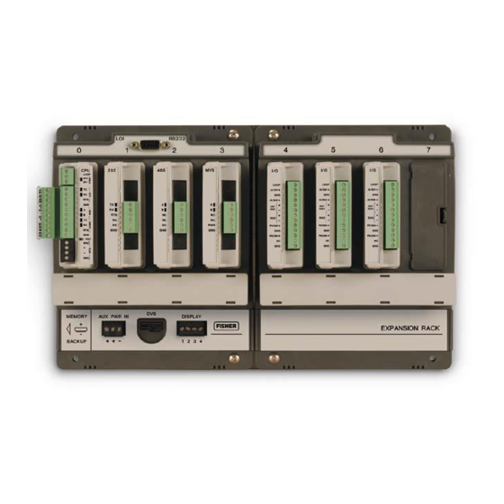
Emerson FloBoss 107 Instruction Manual (152 pages)
Flow Manager
Brand:
Emerson
| Category:
Controller
| Size: 7.04 MB
Table of Contents
Table of Contents
3
Chapter 1 - General Information
7
Scope of Manual
8
Floboss 107 Overview
8
Requirements
8
Device
8
Devices
8
Hardware
11
Processor and Memory
12
Backplane
12
Expansion Rack
12
Central Processing Unit (CPU)
12
Battery and Super-Capacitor
14
Built-In Inputs and Outputs
14
Built-In Communications
14
Built-In Resistance Thermal Device (RTD)
16
Built-In Loop Output Power
16
Optional Inputs and Outputs
16
Optional Communication Modules - COM3
17
Enhanced Communication Module
17
Optional Multi-Variable Sensor (MVS)
18
Optional Integral Sensors
18
Optional License Key
18
Optional Enclosures
18
Optional LCD Touchpad
19
Polycarbonate Enclosure with a DVS Module
19
Firmware
20
History Points
21
Extended History
21
Alarm Log
22
Event Log
23
Security
23
I/O Database
24
Function Sequence Tables (FST)
24
PID Control
24
Spontaneous-Report-By-Exception (SRBX) Alarming
25
Softpoints
25
Opcodes
25
Pass through Communications
25
ROC and Modbus Protocols
25
User C Programs
26
ROCLINK ™ 800 Configuration Software
26
Roclink
26
Product Electronics
28
Real-Time Clock
28
Diagnostic Monitoring
28
Automatic Self Tests
28
Low Power Mode
29
Flow Measurements
29
Security Gateway
30
Additional Technical Information
31
Chapter 2 - Installation and Use
33
Installation Requirements
33
Environmental Requirements
33
Site Requirements
34
Side and Front View of Floboss 107 Base Unit
35
Compliance with Hazardous Area Standards
36
Power Installation Requirements
36
Grounding Installation Requirements
37
Power Connection on Base Unit
37
I/O Wiring Requirements
38
Installing the Floboss 107 and Expansion Rack
39
Required Tools
39
Installing the Floboss 107 Without an Expansion Rack
39
Installing the Floboss with an Expansion Rack
40
Adapter Plate (FB107 Base Unit)
40
Expansion Rack
41
Adapter Plate (FB107 Expansion Rack)
41
Removing an Expansion Rack
42
Removing and Installing Module Slot Covers
43
Removing and Installing Wire Channel Covers
43
Memory Backup Battery
44
Removing and Installing the Battery
44
Central Processor Unit (CPU)
45
Removing the CPU Module
47
Installing the CPU Module
48
Resetting the CPU
48
License Keys
48
Startup and Operation
49
Startup
49
Operation
49
Chapter 3 - Power Connections
51
Power Input Descriptions
51
Determining Power Consumption
53
Wiring Connections
56
Summary
56
Wiring Power to the CPU Module
57
Chapter 4 - Inputs and Outputs
59
I/O Description
59
CPU Module
60
Module's Optional I/O Assembly
60
I/O Module
61
Installing a Module
63
Removing a Module
64
Wiring a Module
65
Selecting the Type of I/O
65
Analog Inputs (AI)
67
Wiring the Analog Inputs
67
Loop Output Power for the CPU
68
8-Point Analog Input/Digital Input (AI/DI) Module
69
Wiring the 8-Point AI/DI
69
Loop Output Power for the I/O Module
69
DI Wiring
70
Analog Outputs (AO)
71
Wiring the Analog Outputs
71
Discrete Inputs (DI)
72
Wiring the Discrete Inputs
73
Discrete Outputs (DO)
73
Wiring the Discrete Outputs
74
4.11 Discrete Outputs Relay (DOR) Module
75
Discrete Output Wiring - High Side Switch(on CPU Module)
75
Discrete Output Wiring - Low Side Switch (on CPU Module )
75
Discrete Output Relay Module Wiring (High Side Switch)
76
Wiring the Discrete Output Relays
76
Pulse Inputs (PI)
77
Wiring the Pulse Inputs
77
Discrete Output Relay Module Wiring (Low Side Switch)
77
4.13 Application (APP 485) Module
78
Wiring the Application Module
78
Pulse Input Wiring (on CPU Module)
78
4.14 Resistance Temperature Detector (RTD) Input
80
Wiring the RTD Input
80
4.15 6-Point AO/DO Module
81
RTD Sensor Wiring (on CPU Module)
81
Wiring the 6-Point AO/DO Module
82
HART Module
82
Discrete Output High Side Switch Wiring
82
Wiring the HART Module
83
4.17 Resistance Temperature Detector (RTD) Module
84
Wiring the RTD Module
84
4.18 IEC 62591 Module
85
Wiring the IEC 62591 Module
86
4.19 Additional Technical Information
86
FB107 IEC 62591 Module Power and Data Wiring to Field Link
86
Chapter 5 - Communications
87
Communications Overview
87
Eia-232
88
Installing/Removing a Communication Module
91
Wiring the Local Operator Interface (LOI) Port
91
5.3.1 Using the LOI
92
Wiring EIA-485 (RS-485) Communications
92
Wiring EIA-232 (RS-232) Communications
93
Eia-485
93
Liquid Crystal Display (LCD) Touchpad
94
Enhanced Communication Module (ECM)
95
Activating the USB Port
96
Device Manager
97
Update Browser Software
98
Pop-Up Menu
100
Dial-Up Modem Module
101
Communication Parameters
101
Network Radio Module (NRM)
102
Installing the NRM
103
5.10 Additional Technical Information
103
Network Radio Module
103
Chapter 6 - Sensors and Transducers
105
Multi-Variable Sensor (MVS) Module Overview
105
Installing/Removing an MVS Module
108
Configuring a Multi-Drop MVS Module Setup
108
Lightning Protection
110
Dual Variable Sensor (DVS) Overview
111
Installing/Removing a DVS
112
Physically Connecting a DVS
113
Configuring a DVS
114
Pressure Module (PIM) Overview
114
Installing/Removing a Pressure Module
115
Configuring a Pressure Module
117
6.4 Additional Technical Information
118
Chapter 7 - Troubleshooting
119
General Guidelines
119
Graphical User Interface (GUI)
120
Checklists
122
Leds
122
Serial Communications
122
Inputs/Outputs
123
Preserving Configuration and Log Data
124
ROCLINK 800 Configuration Software
124
Powering up
125
Multi-Variable Sensor (MVS)
125
Resistance Temperature Detector (RTD)
125
IEC 62591 Module
126
Network Radio Module (NRM)
126
Procedures
126
Resetting the FB107
127
Restarting and Reconfiguring the FB107
127
Troubleshooting Analog Inputs
128
Troubleshooting Analog Outputs
129
Troubleshooting Discrete Inputs
130
Troubleshooting Discrete Outputs
130
Troubleshooting Pulse Inputs
131
Troubleshooting RTD Inputs
131
Troubleshooting the Multi-Variable Sensor (MVS)
133
Troubleshooting the Enhanced Comm Module (ECM)
134
Troubleshooting the Dual Variable Sensor (DVS)
134
Troubleshooting the Pressure Module (PIM)
135
Troubleshooting AI/DI
136
Troubleshooting the Discrete Output Relay (DOR)
136
Appendix A - Glossary
137
Electromagnetic Interference
139
Advertisement
Emerson FloBoss 107 Instruction Manual (118 pages)
Flow Manager
Brand:
Emerson
| Category:
Measuring Instruments
| Size: 3.29 MB
Table of Contents
Table of Contents
3
Chapter 1 - General Information
7
Scope of Manual
8
Floboss 107 Overview
8
Hardware
11
Processor and Memory
12
Backplane
12
Expansion Rack
12
Central Processing Unit (CPU)
12
Battery and Super-Capacitor
14
Built-In Inputs and Outputs
14
Built-In Communications
14
Built-In Resistance Thermal Device (RTD)
16
Built-In Loop Output Power
16
Optional Inputs and Outputs
16
Optional Communication Module - COM3
17
Optional Multi-Variable Sensor (MVS)
17
Optional License Key
18
Firmware
18
History Points
19
Alarm Log
21
Event Log
21
Security
22
I/O Database
22
Function Sequence Tables (FST)
22
PID Control
22
Spontaneous-Report-By-Exception (SRBX) Alarming
23
Softpoints
23
Opcodes
23
Pass through Communications
24
ROC and Modbus Protocols
24
User C Programs
24
ROCLINK 800 Configuration Software
25
Product Electronics
26
Real-Time Clock
26
Diagnostic Monitoring
26
Automatic Self Tests
27
Low Power Mode
27
Flow Measurements
27
Additional Information
29
Chapter 2 - Installation and Use
31
Installation Requirements
31
Environmental Requirements
31
Site Requirements
32
Compliance with Hazardous Area Standards
34
Power Installation Requirements
35
Grounding Installation Requirements
35
Installing Grounding for the Floboss 107
36
I/O Wiring Requirements
37
Installing the Floboss 107 and Expansion Rack
37
Required Tools
37
Installing the Floboss 107 Without an Expansion Rack
38
Installing the Floboss with an Expansion Rack
39
Removing an Expansion Rack
41
Removing and Installing Module Covers
41
Removing and Installing Wire Channel Covers
42
Memory Backup Battery
42
Removing and Installing the Battery
43
Central Processor Unit (CPU)
43
Removing the CPU Module
44
Installing the CPU Module
45
License Keys
46
Startup and Operation
46
Startup
46
Operation
47
Chapter 3 - Power Connections
49
Power Input Descriptions
49
Determining Power Consumption
49
Wiring Connections
56
Wiring Power to the CPU Module
57
Chapter 4 - Inputs/Outputs and RTD Inputs
59
I/O Description
59
Installing a Module
63
Removing a Module
64
Wiring a Module
64
Selecting the Type of I/O
65
Analog Inputs (AI)
67
Wiring the Analog Inputs
67
Analog Outputs (AO)
69
Wiring the Analog Outputs
69
Discrete Inputs (DI)
70
Wiring the Discrete Inputs
71
Discrete Outputs (DO)
71
Wiring the Discrete Outputs
72
Pulse Inputs (PI)
73
Wiring the Pulse Inputs
74
Resistance Temperature Detector (RTD) Input
74
Wiring the RTD Input
75
Chapter 5 - Communications
77
Communications Overview
77
Installing/Removing a Communications Module
80
Wiring the Local Operator Interface (LOI) Port
81
Using the LOI
81
Wiring EIA-485 (RS-485) Communications
82
Wiring EIA-232 (RS-232) Communications
83
Wiring the Liquid Crystal Display (LCD)
84
Chapter 6 - Multi-Variable Sensor (MVS)
85
MVS Overview
85
Installing/Removing an MVS Module
87
Configuring a Multi-Drop MVS Module Setup
87
MVS Lightning Protection
89
Chapter 7 - Troubleshooting
91
General Guidelines
91
Graphical User Interface (GUI)
92
Checklists
93
Leds
93
Serial Communications
93
Inputs/Outputs
94
Preserving Configuration and Log Data
95
ROCLINK 800 Configuration Software
95
Powering up
96
Multi-Variable Sensor (MVS)
96
Resistance Thermal Device (RTD)
97
Procedures
97
Resetting the FB107
97
Restarting and Reconfiguring the FB107
98
Troubleshooting Analog Inputs
98
Troubleshooting Analog Outputs
99
Troubleshooting Discrete Inputs
100
Troubleshooting Discrete Outputs
101
Troubleshooting Pulse Inputs
101
Troubleshooting RTD Inputs
102
Troubleshooting MVS
103
Appendix A - Glossary
105
Emerson FloBoss 107 User Manual (64 pages)
Flow Manager
Brand:
Emerson
| Category:
Controller
| Size: 1.36 MB
Table of Contents
Table of Contents
3
Chapter 1 - Introduction
5
Scope and Organization
5
Overview
5
FB107 Touchpad
6
Display Mode
8
BLM Mode
9
Initial Active Touchpad Displays
9
Power Savings Mode
9
Touchpad and ROCLINK 800 Security
10
Chapter 2 - Configuration
11
Configuring the Port Owner
11
LCD Controller
12
Emerson Process Management Logos
13
Configuring Touchpad Options
14
Configuring Basic List Mode (BLM)
15
Configuring Standard or Normal Mode
17
Configuring Chart Mode
18
Chart Mode
18
Touchpad Main Menu
18
Configuring Touchpad Security
19
Data Source
19
Data Point
19
Device Security
20
Chapter 3 - Using the Touchpad
23
Touchpad Screens
23
Menu Screens
23
Configuring Touchpad Security
23
Parameter Screens
24
Sample Parameter
24
Numeric Keypad
24
Dynamic Charts
25
Edited Parameter
25
Revised Scales
26
Operational Screens
27
Touchpad Time out
27
Logging on
28
Log on
28
Touched Value
29
Touchpad Main Menu
31
LCD User List - Chart
31
User Lists
32
LCD User List
32
User List Menu
33
Meter Runs
34
Numeric Keypad
34
User List Parameters
34
Displaying Meter Information
35
Meter Menu
35
Meter Run Menu
35
Changing a Plate
36
Module Information
37
Viewing I/O and Diagnostic Information
37
Viewing RTD Information
38
Viewing COMM Information
39
Viewing Multiple Variable Sensor (MVS) Information
40
Viewing Meter Information
41
Viewing System Information
42
Viewing Dual Variable Sensor (DVS) Information
43
Calibrating a Point
44
Charts
48
Viewing Historical Data
49
Viewing Dynamic Data
50
PID Loops
51
Setting Basic PID Loops
52
Setting Advanced PID Loops
54
System Information
56
Displaying System Information
56
Saving a Configuration
57
Performing a Warm Start
58
Forcing End of Day
58
Idle State Display
58
Adjusting Touchpad Contrast
59
Logging off
60
Advertisement
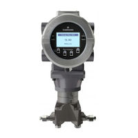
Emerson FloBoss 107 Site Considerations For Equipment Installation, Grounding, And Wiring Manual (42 pages)
Brand:
Emerson
| Category:
Measuring Instruments
| Size: 1.65 MB
Table of Contents
Table of Contents
3
Section 1: Overview
5
Safety Labels
5
Major Topics
6
Section 2: Protection
7
Protecting Equipment Systems
7
Quality Is Conformance to Requirements
7
Protecting Equipment and Personnel
7
Considerations for Protecting Personnel
8
Considerations for Protecting Equipment
8
Other Site Safety Considerations
9
Section 3: Grounding and Isolation
11
Power and Ground Systems
11
Importance of Good Grounds
11
Earth Ground Connections
11
Establishing a Good Earth Ground
12
Ground Wire Considerations
15
Other Grounding Considerations
16
Isolating Equipment from the Pipeline
17
Meter Runs Without Cathodic Protection
17
Meter Runs with Cathodic Protection
18
Section 4: Lightning Arresters and Surge Protectors
21
Strike
21
Chance of Being Struck by Lightning
21
Antenna Caution
24
Ground Propagation
26
Tying It All Together
26
Impulse Protection Summary
26
Use of Lightning Arresters and Surge Protectors
27
Installing Lightning Arresters and Surge Protectors
27
Section 5: Wiring Techniques
31
Overview
31
Device Wiring
31
Avoid Common Returns
31
Use Twisted Shielded Pair Wiring (with Overall Insulation)
32
Ground Cable Shields
32
Use Known Good Earth Grounds
33
Earth-Ground Wires
33
Work Neatly and Professionally
33
Observe High Power Conductors and Signal Warning
33
Use Proper Wire Size
33
Use Lightning Arresters & Surge Protectors
34
Secure Wiring Connections
34
Section 6: Grounding and Bonding a Solar PV Array
37
Code Requirements
37
Ground Attachment
37
Non-Conductive Components
38
Non-Conductive Coatings
38
Grounding Method
39
Corrosion Protection
40
Lightning Protection Considerations
40
Advertisement
Related Products
Emerson fisher 1008
Emerson Fisher 1078
Emerson Fisher 1098-EGR
Emerson Fisher 1098H-EGR
Emerson Fisher 1069
Emerson Fisher 1066SR
Emerson Fisher 1052 F
Emerson Fisher 1052 G
Emerson 135
Emerson 1929
Emerson Categories
Controller
Control Unit
Transmitter
Measuring Instruments
Fan
More Emerson Manuals
Login
Sign In
OR
Sign in with Facebook
Sign in with Google
Upload manual
Upload from disk
Upload from URL