Table of Contents
Advertisement
Quick Links
Site Considerations for Equipment Installation, Grounding, and Wiring Manual
D301452X012
October 2019
Site Considerations for Equipment
Installation, Grounding, and Wiring
Manual
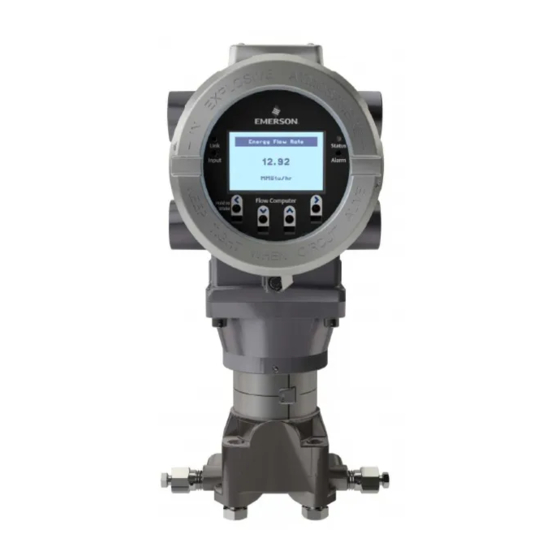
FB3000 Remote Terminal Unit (RTU)
FB1100/1200 Flow Computer
FB2100/2200 Flow Computer
ROC800, FloBoss
™
107, ControlWave
™
Family of Flow Computers and RTUs
Remote Automation Solutions
Advertisement
Table of Contents


Need help?
Do you have a question about the ControlWave Series and is the answer not in the manual?
Questions and answers