Table of Contents
Advertisement
Quick Links
Download this manual
See also:
Instructions for Using
Advertisement
Table of Contents
Troubleshooting

Related Manuals for Emerson FloBoss 103


Summary of Contents for Emerson FloBoss 103
- Page 1 Part Number D301153X012 August 2017 ™ FloBoss 103 and 104 Flow Manager Instruction Manual FloBoss 103 FloBoss 104 Remote Automation Solutions...
- Page 2 FloBoss 103/104 Instruction Manual Revision Tracking Sheet August 2017 This manual may be revised periodically to incorporate new or updated information. The revision date of each page appears at the bottom of the page opposite the page number. A change in revision date to any page also changes the date of the manual that appears on the front cover.
-
Page 3: Table Of Contents
Compliance with Hazardous Area Standards ..............2-3 Mounting ............................2-4 2.3.1 General Guidelines ......................2-4 2.3.2 Pipe Stand Mounting (FloBoss 103/FloBoss 104) ............. 2-7 2.3.3 Orifice Plate Mounting (FloBoss 103) ................2-7 2.3.4 Meter Mounting (FloBoss 104) ................... 2-8 Startup and Operation ........................2-11 2.4.1... -
Page 4: Power
FloBoss 103/104 Instruction Manual Configuration ..........................2-13 Chapter 3 – Power Connections Power Installation Requirements ....................3-1 Grounding Installation Requirements ....................3-2 3.2.1 Grounding Guidelines ......................3-2 3.2.2 Installing Grounding for the FB100 ..................3-3 Determining Power Requirements ....................3-4 Solar Powered Installations......................3-4 3.4.1... -
Page 5: Troubleshooting
FloBoss 103/104 Instruction Manual Chapter 7 – Pulse Interface Module Pulse Interface Module ........................7-1 7.1.1 Making Process Connections..................... 7-3 7.1.2 Configuring the Pulse Interface Module ................7-3 Chapter 8 – Calibration Calibration (AI, RTD & Meter) ......................8-1 Performing a Calibration ........................ 8-1 Adjusting for Zero Shift ........................ - Page 6 FloBoss 103/104 Instruction Manual [This page is intentionally left blank.] Revised August-2017...
-
Page 7: Chapter 1 - General Information
FloBoss 103/104 Instruction Manual Chapter 1 – General Information In This Chapter Scope of Manual ................1-1 Product Overview ................1-2 1.2.1 Components and Features ........... 1-3 1.2.2 Hardware ................1-5 1.2.3 Firmware ................1-8 1.2.4 Options and Accessories ............1-9 1.2.5 FCC Information .............. -
Page 8: Product Overview
FloBoss 103/104 Instruction Manual Chapter 4 Provides information on the various I/O capabilities Input/Output of the FB100. Chapter 5 Provides information on the communications Communications capabilities of the FB100. Chapter 6 Provides information on the dual-variable sensor that Dual-Variable Sensor provides static and differential pressure inputs. -
Page 9: Components And Features
FloBoss 103/104 Instruction Manual 1.2.1 Components and Features The FB100 provides the following components and features: ▪ Weather-tight enclosure ▪ Termination printed circuit board (“Termination module”) ▪ 32-bit processor print circuit board (“Processor module”) ▪ Battery charger printed circuit board. (“Battery Charger module”) ▪... -
Page 10: Liquid Crystal Display
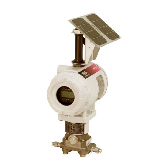
FloBoss 103/104 Instruction Manual Field conduit entry Optional solar panel mounts here Liquid crystal display (LCD) Dual variable sensor (DVS) Figure 1-1. FloBoss 103 Flow Manager with LCD Liquid crystal display (LCD) Pulse interface module Optional solar panel Pressure transducer Figure 1-2. -
Page 11: Hardware
FloBoss 103/104 Instruction Manual The enclosure is fabricated from die-cast aluminum alloy with iridite plating and paint. The NEMA 4 enclosure protects the electronics from physical damage and harsh environments. The caps at either end of the enclosure unscrew to allow field maintenance. Two ¾-14 pipe-threaded holes permit field conduit wiring and communications. - Page 12 FloBoss 103/104 Instruction Manual Termination Located in the terminal side of the explosion-proof housing, the Module termination module provides connections to the field wiring. Refer to Figure 1-4. Local operator interface (LOI) COM2 Power supply I/O field wiring LOI (COM1) Figure 1-4.
-
Page 13: Termination Board
FloBoss 103/104 Instruction Manual Display (LCD) drivers; and controls for the Dual-Variable Sensor (DVS), the Pulse Interface module, and the optional I/O termination points. The microprocessor has low-power operating modes, including inactivity and low battery condition. The FB100 comes standard with 512 KB of built-in, static random access memory (SRAM) for storing data and history. -
Page 14: Firmware
FloBoss 103/104 Instruction Manual (DVS) or a Pulse Interface module. Three diagnostic analog inputs (AI) monitor the battery voltage, logical voltage, and enclosure/battery temperature. Refer to Chapter 4, Input/Output. Communications The Local Operator Interface (LOI) port provides a direct, local link between the FB100-Series and a PC through a Local Operator Interface cable using EIA-232 (RS-232) communications. -
Page 15: Options And Accessories
FloBoss 103/104 Instruction Manual ▪ Alarm call-in to host for Spontaneous-Report-By-Exception (SRBX) ▪ User-level security. 1.2.4 Options and Accessories The FB100 supports the following options and accessories: ▪ Communication modules for either EIA-232 (RS-232), EIA-485 (RS-485), dial-up modem ▪ 6 Input/Output (I/O) termination points ▪... -
Page 16: Fcc Information
FloBoss 103/104 Instruction Manual 1.2.5 FCC Information This equipment complies with Part 68 of the FCC rules. Etched on the modem assembly is, among other information, the FCC certification number and Ringer Equivalence Number (REN) for this equipment. If requested, this information must be provided to the telephone company. -
Page 17: Flow Measurement
FloBoss 103/104 Instruction Manual 1.3.1 Flow Measurement The primary function of the FB100-Series is to measure the flow of natural gas through an orifice or turbine or rotary meter in accordance with the 1992 American Petroleum Institute (API) and American Gas Association (AGA) standards. -
Page 18: History Points
FloBoss 103/104 Instruction Manual Accumulation energy over the calculation period. The flow and energy are then accumulated and stored at the top of every hour. At the configured contract hour, the flow and energy are then stored to the Daily Historical Log and zeroed for the start of a new day (contract hour). -
Page 19: Hourly Historical Log
FloBoss 103/104 Instruction Manual IMV (Integral Multiplier Value) for AGA3 (Average) or BMV (Base Multiplier Value) for AGA7 (Average). Pressure Extension for AGA3 (Average) or Today’s Total for AGA7 (Totalize). Instantaneous Flow (Accumulate). Instantaneous Energy (Accumulate). History Point 2 (AGA3), History Point 3, History Point 4, and History... - Page 20 FloBoss 103/104 Instruction Manual Extended History The FB100 has configurable archive times (1 minute to 60 minutes) which, in turn, determine the number of entries. Alarm Log The Alarm Log contains the change in the state of any alarm signal that has been enabled for alarms.
-
Page 21: Security
FloBoss 103/104 Instruction Manual temperature, pressure, Reynolds number, and warnings for orifice diameter, pipe diameter, and beta ratio. 1.3.3 Security The FB100 provides for security within the unit. A maximum of 16 log- on identifiers (IDs) may be stored. In order for the unit to communicate, the log-on ID supplied to ROCLINK 800 software must match one of the IDs stored in the FB100. -
Page 22: Pass Through Communications
FloBoss 103/104 Instruction Manual 1.3.7 Pass Through Communications Pass Through Communications allow you to configure an FB100 unit to send Pass Through messages, when using a FB100. By using any of the FB100 communications ports, Pass Through Mode allows data to be received by one unit and then passed through to other devices connected on any other communications port. -
Page 23: Processor And Memory
FloBoss 103/104 Instruction Manual ▪ EIA-485 (RS-485) communications (Comm 1) terminations ▪ RTD input terminations ▪ Optional I/O and terminations ▪ Remote charge terminations ▪ Optional Comm 2 terminations 1.4.2 Processor and Memory The FB100-Series derives processing power from a 32-bit microprocessor. - Page 24 FloBoss 103/104 Instruction Manual Local Operator Interface The Local Operator Interface (LOI) port provides direct (LOI) Port communications between the FB100 and the serial port of an operator interface device, such as personal computer using an EIA-232 (RS-232) link. The interface allows you to access the FB100 (using ROCLINK 800 software) for configuration and transfer of stored data.
-
Page 25: Rtd Input
FloBoss 103/104 Instruction Manual The Comm 2 port is capable of initiating a message in support of Spontaneous-Report-by-Exception (SRBX) alarming. Refer to Chapter 3 for additional information. One of the following card types can be accommodated: ▪ EIA-232 (RS-232) for asynchronous serial communications (baud rate up to 19,200). -
Page 26: Low Power Mode
If the battery voltage drops below 5.4 volts, the FB100 automatically shuts down. The FloBoss 103 monitors its orifice-metering Dual-Variable Sensor for accurate and continuous operation. The FloBoss 104 monitors its Pulse Interface Module. -
Page 27: Additional Technical Information
FloBoss 103/104 Instruction Manual 1.5 Additional Technical Information Refer to Table 1-1 for additional and most-current technical documents (available at www.EmersonProcess.com/Remote). Table 1-1. Additional Technical Information Name Form Number Part Number FloBoss™ 103 Flow Manager FB103 D301152X012 FloBoss™ 104 Flow Manager... - Page 28 FloBoss 103/104 Instruction Manual [This page is intentionally left blank.] 1-22 General Information Revised August-2017...
-
Page 29: Chapter 2 - Installation And Use
2.2.3 Compliance with Hazardous Area Standards ...... 2-3 Mounting ..................2-4 2.3.1 General Guidelines ............... 2-4 2.3.2 Pipe Stand Mounting (FloBoss 103) ........2-7 2.3.3 Orifice Plate Mounting (FloBoss 103) ........2-7 2.3.4 Meter Mounting (FloBoss 104) ..........2-8 Startup and Operation ..............2-11 2.4.1 Starting the FB100 ............. -
Page 30: Installation Requirements
FloBoss 103/104 Instruction Manual Place the meter run in service and monitor with ROCLINK 800 software for proper operation. 2.2 Installation Requirements Careful planning helps to ensure a smooth installation. Be sure to consider location, ground conditions, climate, and site accessibility, as well as the suitability of the FB100-Series application while planning an installation. -
Page 31: Site Requirements
FloBoss 103/104 Instruction Manual 2.2.2 Site Requirements Careful consideration in locating the FB100 on the site can help prevent future operational problems. Consider the following when choosing a location: ▪ Local, state, and federal codes often place restrictions on monitoring locations and dictate site requirements. -
Page 32: Mounting
You can mount the FB103 either of two ways: ▪ On a pipe stand: The FloBoss 103 can mount to a 2-inch pipe stand. Ensure that the pipe stand meets all weight requirements and installation conforms to local building codes. -
Page 33: Processor Connections
FloBoss 103/104 Instruction Manual ▪ On an orifice plate: Directly mount to an orifice plate via a 3- or 5-valve manifold. With either mounting method, the pressure inputs must be piped to the process connections on the DVS. For more information on process connections, refer to Chapter 6. - Page 34 FloBoss 103/104 Instruction Manual Figure 2-2. Dimensions of FB104 Figure 2-3. Dimensions with 2-watt Solar Panel and LCD Installation and Use Revised August-2017...
-
Page 35: Pipe Stand Mounting (Floboss 103/Floboss 104)
FloBoss 103/104 Instruction Manual 2.3.2 Pipe Stand Mounting (FloBoss 103/FloBoss 104) To install the FloBoss 103/ FloBoss 104 on a 2-inch pipe stand: Install the pipe stand per the directions included with the pipe stand. Remove the orifice/meter run from service. -
Page 36: Meter Mounting (Floboss 104)
FloBoss 103/104 Instruction Manual Figure 2-5. FB104 Mounting Option for ATEX unit 2.3.4 Meter Mounting (FloBoss 104) The factory installs the Pulse Interface module to the base of the FB104. Do not remove the FB104 from the Pulse Interface module; you may damage cable connections between the interface and the FB100-Series backplane. -
Page 37: Mounting Pulse Interface Module To Meter Housing
FloBoss 103/104 Instruction Manual Pulse Interface Module Meter Adapter Dowel pins extend 1.25 in min. Meter housing User-supplied 5/16-18 cap screws Shaft adapter 0.68 – 0.71 in Figure 2-6. Mounting Pulse Interface Module to Meter Housing on non-ATEX FB104 Rotary Meter... -
Page 38: Magnet Installed On Long Shaft Adaptor
FloBoss 103/104 Instruction Manual Thread the magnet assembly on to the shaft adaptor until the top of the magnet is between 0.68–0.71 inches above the meter housing (refer to Figure 2-6). The magnet set-screw should be positioned over a flat in the hex shaft adaptor. Tighten the set-screw to lock the magnet assembly in place. -
Page 39: Startup And Operation
FloBoss 103/104 Instruction Manual Remove the two dowel pins. In their place, install two 5/16-18 x 7/8 long bolts and lock washers. Securely tighten all cap screws attaching the FB104 to the meter. Once you install the Pulse Interface module to the meter, the pressure transducers are attached to the process. -
Page 40: Operation
FloBoss 103/104 Instruction Manual – ON/OFF power jumper NORM RESET jumper Figure 2-9. On/Off Power Jumper (FB103 with Optional LCD) Reattach the top-end cap cover (LCD end). Screw the cover on until metal contacts metal. Do not over-tighten the cover. -
Page 41: Configuration
FloBoss 103/104 Instruction Manual procedures in a hazardous area could result in personal injury or property damage. During operation, you can monitor the FB100 (to view or retrieve current and historical data) either locally or remotely. Accomplish local monitoring either by viewing the LCD panel or by using ROCLINK 800 software on a PC connected through the LOI port. - Page 42 FloBoss 103/104 Instruction Manual [This page is intentionally left blank.] 2-14 Installation and Use Revised August-2017...
-
Page 43: Chapter 3 - Power Connections
The FB100 accepts input voltages from 8.0 volts to 28 volts at the charge (CHG+ / CHG-) terminals on the termination board. Note The maximum power usage for DC voltage sources is 130 mW for the FloBoss 103 and 300 mW for the FloBoss 104, excluding battery charging. Revised August-2017 Power Connections... -
Page 44: Grounding Installation Requirements
FloBoss 103/104 Instruction Manual Do not allow the batteries to fully discharge. Either keep providing input Caution power or turn the device off. If the batteries fully discharge, the battery charger board may enter thermal limiting, which prevents the batteries from overheating but restricts input power. -
Page 45: Installing Grounding For The Fb100
FloBoss 103/104 Instruction Manual 3.2.2 Installing Grounding for the FB100 The FB100 unit has two grounding screws inside the enclosure and one grounding screw outside the enclosure. For the grounding screw locations, refer to Figure 3-1. The grounding installation method for the FloBoss 100-Series depends on whether the pipeline has cathodic protection. -
Page 46: Determining Power Requirements
(in mW) of any other devices used with the FB100 in the same power system. The maximum power for DC voltage sources is 130 mW for the FloBoss 103 and 300 mW for the FloBoss 104, not including the battery charging. -
Page 47: Sizing The Solar Panel
FloBoss 103/104 Instruction Manual Solar arrays generate electrical power for the FB100 from solar radiation. The size of solar panels required for a particular installation depends on several factors, including the power consumption of all devices connected to the solar array and the geographic location of the installation. -
Page 48: Batteries
FloBoss 103/104 Instruction Manual Notes: ▪ The “I panel” value varies depending on the type of solar panel installed. Refer to the vendor’s specifications for the solar panel being used. ▪ The FB100 can accept a maximum of about 1 Amp, limited by its charging circuit. -
Page 49: Determining Battery Requirements
FloBoss 103/104 Instruction Manual In these circumstances, remove the battery charger module (part W38231X0032) and use the FB103 or FB104 without internal power batteries. Refer to Section 3.5.3, Replacing the Batteries, for instructions on removing the battery charger module or contact Remote Automation Solutions LifeCycle Services for assistance in removing the battery charger module. -
Page 50: Wiring Connections
FloBoss 103/104 Instruction Manual 3.6 Wiring Connections The following paragraphs describe how to connect the FB100 to power, I/O devices, and communications devices. Use the recommendations and procedures described in the following paragraphs to avoid damage to equipment. : Check the input power polarity before turning on the power. -
Page 51: Connecting Main Power Wiring
(CHG+ / CHG-) with no external current limiting (internal current limit is 200 mA). The maximum power for DC voltage sources is 130 mWatts for the FloBoss 103 and 300 mWatts for the FloBoss 104, not including battery charging. -
Page 52: Backing Up Configuration And Log Data
FloBoss 103/104 Instruction Manual It is important to use good wiring practices when sizing, routing, and connecting power wiring. Ensure that all wiring conforms to state, local, and NEC codes. The CHG+ / CHG- terminal can accommodate up to 16 AWG wire. -
Page 53: Chapter 4 - Input/Output
FloBoss 103/104 Instruction Manual Chapter 4 – Input/Output In This Chapter I/O Description ................. 4-1 4.1.1 Selecting the Type of I/O ............4-2 I/O Wiring Requirements ..............4-3 Analog Input ..................4-3 4.3.1 Wiring the Analog Input ............4-3 Analog Output .................. 4-4 4.4.1 Wiring the Analog Output (6-point I/O Board) ...... -
Page 54: Selecting The Type Of I/O
FloBoss 103/104 Instruction Manual 4.1.1 Selecting the Type of I/O To select the type of output for the Analog Output/Discrete Output #1 channel, flip the AO/DO switch on the termination board to the desired position. Refer to Figure 4-1 for the switch location. Then select the desired output type on the Configure >... -
Page 55: I/O Wiring Requirements
FloBoss 103/104 Instruction Manual 4.2 I/O Wiring Requirements I/O wiring requirements are site and application dependent. Local, state, or NEC requirements determine the I/O wiring installation methods. Direct burial cable, conduit and cable, or overhead cables are options for I/O wiring installations. -
Page 56: Analog Output
FloBoss 103/104 Instruction Manual Figure 4-2. Analog Input Wiring 4.4 Analog Output The Analog Output (AO) on the 6-point I/O termination board provides a 4–20 mA current source. The analog outputs use a 12-bit D/A converter with A/D values of 0 and 4095. -
Page 57: Wiring The Analog Output (4-Point I/O Board)
FloBoss 103/104 Instruction Manual 4.4.2 Wiring the Analog Output (4-point I/O Board) Figure 4-4 shows the analog output wired as a current source, where AO+ Positive Current control Common Control 1-5V output 4-20mA current device – External power – Figure 4-4. 4–20 mA Analog Output Current Control... -
Page 58: Wiring The Discrete Input
FloBoss 103/104 Instruction Manual : The selectable analog inputs/discrete input channels should have Note the 250-ohm resistor disabled when configured for use as discrete inputs. 4.5.1 Wiring the Discrete Input Figure 4-6 shows the terminals for connecting the DI wiring. The “+”... -
Page 59: Wiring The Discrete Output
FloBoss 103/104 Instruction Manual ▪ Toggle mode. ▪ Latched mode. ▪ Timed discrete output (TDO) mode. : The switch for the selectable Analog Output/Discrete Output Note (DO-1) should be in the DO position, when configured for use as a Discrete Output. -
Page 60: Rtd Input
FloBoss 103/104 Instruction Manual Figure 4-8. Pulse Input Wiring 4.8 RTD Input The temperature is input through the Resistance Temperature Detector (RTD) probe and circuitry. The RTD temperature probe mounts directly to the piping using a thermowell, outside the FloBoss enclosure. The RTD probe is then wired to the FloBoss RTD connections. -
Page 61: Chapter 5 - Communications
FloBoss 103/104 Instruction Manual Chapter 5 – Communications In This Chapter Communications Overview .............. 5-1 EIA-485 (RS-485) Communications Wiring ........5-2 Local Operator Interface Port Wiring ..........5-2 Serial Communications Card ............5-3 Dial-up Modem Communications Card ..........5-4 This chapter describes the communications ports and cards available for FB100. -
Page 62: Rs-485) Communications Wiring
FloBoss 103/104 Instruction Manual LOI port Comm 2 port Comm 1 port Figure 5-1. Communication Port Locations on Termination Board 5.2 EIA-485 (RS-485) Communications Wiring The EIA-485 communication accommodates RS-485 and EIA-485 signals on the Comm 1 port located on the termination board. -
Page 63: Serial Communications Card
FloBoss 103/104 Instruction Manual ® Windows operating system. A prefabricated operator interface cable is available as an accessory. Refer to Figure 5-2. The LOI port is intended for use with a PC running ROCLINK 800 software. This LOI port is compatible with EIA-232 (RS-232) levels. -
Page 64: Dial-Up Modem Communications Card
FloBoss 103/104 Instruction Manual Table 5-2. Communications Card Signals Signals Action The request to send signals that the modem is ready to transmit. The RXD receive data signals that data is being received at the communications card. The TXD transmit data signals that data is being transmitted from the communications card. - Page 65 FloBoss 103/104 Instruction Manual Delay, and 10 millisecond Key Off Delay. On power up, the modem must be set up for Auto Answer. Periodic checks are made to ensure that the modem is still in Auto Answer or that it is not left off the hook after a certain period of non-communication.
- Page 66 FloBoss 103/104 Instruction Manual [This page is intentionally left blank.] Communications Revised August-2017...
-
Page 67: Chapter 6 - Dual-Variable Sensor (Dvs)
FloBoss 103/104 Instruction Manual Chapter 6 – Dual-Variable Sensor (DVS) In This Chapter Dual-Variable Sensor ............... 6-1 6.1.1 Making Process Connections ..........6-2 6.1.2 Configuring the DVS ............. 6-2 This chapter describes the Dual-Variable Sensor (DVS), which provides differential pressure and static pressure inputs to the FB103 for orifice flow calculation. -
Page 68: Making Process Connections
FloBoss 103/104 Instruction Manual : Consult your local sales representative for special ranges. Note 6.1.1 Making Process Connections Piping from the meter run connects to the DVS. Both the static and differential pressure sensors connect to female ¼-18 NPT connections on the bottom of the DVS. - Page 69 FloBoss 103/104 Instruction Manual pressure, RTD, and enclosure/battery temperature, to the selected metric mode. : When you select metric mode, realize that the FB103 adjusts Note only the Units. You must manually change all values to the proper unit of measurement.
- Page 70 FloBoss 103/104 Instruction Manual [This page is intentionally left blank.] Dual-Variable Sensor Revised August-2017...
-
Page 71: Chapter 7 - Pulse Interface Module
FloBoss 103/104 Instruction Manual Chapter 7 – Pulse Interface Module In This Chapter Pulse Interface Module ..............7-1 7.1.1 Making Process Connections ..........7-3 7.1.2 Configuring the Pulse Interface Module ....... 7-3 This chapter describes the Pulse Interface module, which provides pressure inputs and pulses counts to the FloBoss 104 for AGA7 flow calculation with AGA8 compressibility. -
Page 72: Static Pressure
FloBoss 103/104 Instruction Manual • Static pressure is sampled once per second. • Temperature is sampled and linearized once per second. Pressure transducer Pulse Interface module Meter adaptor Figure 7-1. FloBoss 104 Assembly The FB104 implements standard PI and AI alarming along with sensor and flow alarms. -
Page 73: Making Process Connections
FloBoss 103/104 Instruction Manual The pressure transducers provide the measurement of the line pressure (P1) and can optionally measure downstream pressure or station inlet pressure (aux P2). The Pulse Interface module is attached to the base of the FB104 at the factory. - Page 74 FloBoss 103/104 Instruction Manual [This page is intentionally left blank.] Pulse Interface Module Revised August-2017...
-
Page 75: Chapter 8 - Calibration
FloBoss 103/104 Instruction Manual Chapter 8 – Calibration In This Chapter Calibration (AI, RTD & Meter) ............8-1 Performing a Calibration ..............8-1 Adjusting for Zero Shift ..............8-7 Verifying a Calibration ..............8-8 This chapter describes the processes for calibrating the AI, RTD, and Meter modules for the FB100-Series devices. - Page 76 Value. The FB100 uses these values in the flow calculations while calibrating the points. Click Freeze. Figure 8-1. Meter Calibration (FloBoss 103 Shown) If you are calibrating a pressure input, read the following Caution, and then isolate the pressure sensors from the process.
-
Page 77: Pressure Calibration Open/Close Orientation
FloBoss 103/104 Instruction Manual Bleed Bleed High Pressure Open Remains Close Close Operating Shutdown Sequence Shutdn2 Figure 8-2. Removing the DVS from Service If you are calibrating a pressure input, set up the pressure calibrator and make the necessary connections to the DVS. Refer to Figure 8-3 for the line orientation during the calibration. -
Page 78: Set Zero Calibration
FloBoss 103/104 Instruction Manual Figure 8-4. Set Zero Calibration Example Apply the low (zero) value. For a pressure input, this would typically be open to atmosphere. Enter the applied value in the Dead Weight / Tester Value field of the Set Zero dialog. Refer to Figure 8-4. For static pressure on an absolute-pressure device, remember to enter the actual current atmospheric pressure, such as 14.73 psi. - Page 79 FloBoss 103/104 Instruction Manual Figure 8-6. Set Midpoint 1 If you are performing a two-point calibration, click Done. Calibration for this input is complete. To calibrate midpoints, apply the desired pressure or temperature and enter the applied value in the Dead Weight / Tester Value field.
- Page 80 FloBoss 103/104 Instruction Manual If you are performing a four-point calibration, click Done. Calibration for this input is complete. To calibrate a third midpoint, apply the desired pressure or temperature and enter the applied value in the Dead Weight / Tester Value field.
-
Page 81: Adjusting For Zero Shift
FloBoss 103/104 Instruction Manual 8.3 Adjusting for Zero Shift If desired, use the zero shift procedure after calibrating the differential pressure input for the FB103. The FB103 calibrates differential pressure without applying line pressure to the sensor. When you connect the sensor back to the process after calibration, a shift in the differential pressure can occur due to the influence of the line pressure. -
Page 82: Verifying A Calibration
FloBoss 103/104 Instruction Manual 8.4 Verifying a Calibration ROCLINK 800 software can verify the calibration to check if the DVS requires re-calibration. To verify the calibration: Start ROCLINK 800 software and connect to the FB100. Select Meter > Calibration. Click Freeze. The Meter Calibration window displays. The current reading displays under each meter input as the Freeze Value. - Page 83 FloBoss 103/104 Instruction Manual Figure 8-12. Verify Calibration To log the Tester Value and the Live Reading to the Event Log as a record of the verification, click Log Verify. Click Done. The Meter Calibration screen displays. Continue to verify all required pressures/values.
- Page 84 FloBoss 103/104 Instruction Manual [This page is intentionally left blank.] 8-10 Calibration Revised August-2017...
-
Page 85: Chapter 9 - Troubleshooting
FloBoss 103/104 Instruction Manual Chapter 9 – Troubleshooting In This Chapter Troubleshooting Guidelines ............. 9-1 Troubleshooting Checklists .............. 9-2 9.2.1 Dial-up Modem ..............9-2 9.2.2 Serial Communications ............9-2 9.2.3 Optional I/O ................9-2 9.2.4 Software Issues ..............9-3 9.2.5 Power Issues ................ 9-3 9.2.6 Dual-Variable Sensor (FB103) .......... -
Page 86: Troubleshooting Checklists
FloBoss 103/104 Instruction Manual Troubleshooting Checklists 9.2.1 Dial-up Modem If you are experiencing troubles with an internal dial-up modem: ▪ Check to make sure you’ve applied power to the FB100. Check the ON/OFF jumper, the wiring connections at CHG+ and CHG-, and the wiring at the power source. -
Page 87: Software Issues
FloBoss 103/104 Instruction Manual : No field repair or replacement parts are associated with the Note I/O termination points. 9.2.4 Software Issues If you are experiencing problems with the FB100 that appear to be software-related, try resetting the FB100. ▪ Use a warm start to restart without losing configuration or log data. -
Page 88: Pulse Interface Module (Fb104)
FloBoss 103/104 Instruction Manual If the input shows a Point Fail alarm, then the sensor is not communicating with the FB100. The DVS contains no user-serviceable or user-replaceable parts. Return the FB100 to your local sales representative for repair or replacement. -
Page 89: Procedures
FloBoss 103/104 Instruction Manual 9.3 Procedures 9.3.1 Preserving Configuration and Log Data Perform this backup procedure before your remove power from the FB100 for repairs, troubleshooting, removing or adding components, or upgrades. This procedure preserves the current flow computer configuration and log data held in RAM. -
Page 90: Restarting And Reconfiguring
FloBoss 103/104 Instruction Manual : This cold start does not include any of the clearing options Note available in a cold start you perform using ROCLINK 800. Unscrew the front end cap cover (LCD end). Place the reset jumper (located on the LCD, if installed, or on the Battery Charger board at J2) in the RST position. -
Page 91: Connecting The Termination Board To The Backplane
Click Download to restore the configuration. 9.3.4 Connecting the Termination Board to the Backplane Older FloBoss 103 units were shipped with the termination board connected to the backplane through a 34-pin interface connector. Your FB103 may have a shrouded connector which ensures the correct polarity. - Page 92 FloBoss 103/104 Instruction Manual Attach this end to backplane first. Attach this end to termination board second Figure 9-2 . 34-Pin Interface Connector Troubleshooting Revised August-2017...
-
Page 93: Appendix A - Glossary
FloBoss 103/104 Instruction Manual Appendix A – Glossary Note: This is a generalized glossary of terms. Not all the terms may necessarily correspond to the particular device or software described in this manual. For that reason, the term “ROC” is used to identify all varieties of Remote Operations Controllers (including ROC800-Series, ROC800L, DL8000, FloBoss™... - Page 94 FloBoss 103/104 Instruction Manual Communications port on a personal computer (PC). (continued) COMM Communications port on a ROC used for host communications. . Note: On FloBoss 500-Series and FloBoss 407s, COMM1 is built-in for RS-232 serial communications. Comm Module Module that plugs into a ROC to provide a channel for communications via a specified communications protocol, such as EIA-422 (RS-422) or HART.
-
Page 95: Flash Rom
FloBoss 103/104 Instruction Manual Distributed RTU Network, in which two or more remotely distributed RTU devices (RRTUs) are wirelessly connected in a peer-to-peer network to share data. (continued) DRTU A primary component of the Distributed RTU Network, consisting of a FB107 chassis housing a focused functionality CPU and a Network Radio module (NRM). -
Page 96: Integral Multiplier Value
(www.fieldbus.org). Compressibility Factor. (continued) Frequency Shift Keypad. Function Sequence Table, a type of user-written program in a high-level language designed by Emerson Process Management’s Flow Computer Division. Foot or feet. Ground Fault Analysis. Gigahertz, 10 cycles per second Electrical ground, such as used by the ROC’s power supply. -
Page 97: Integral Value
FloBoss 103/104 Instruction Manual Integral Value. Kilobytes. KiloHertz. Liquid Crystal Display. Local Display Panel, a display-only device that plugs into ROC300-Series units (via a parallel interface cable) used to access information stored in the ROC. Light-Emitting Diode. Logical Number The point number the ROC and ROC Plus protocols use for I/O point types are based on a physical input or output with a terminal location;... - Page 98 FloBoss 103/104 Instruction Manual (continued) Node A basic structural component of the Distributed RTU Network. A node (usually a FB107 chassis housing a focused-functionality CPU and a Network Radio module) provides a data collection point that wirelessly transmits data throughout the designed network.
-
Page 99: Built-In
FloBoss 103/104 Instruction Manual Protocol A set of standards that enables communication or file transfers between two computers. Protocol parameters include baud rate, parity, data bits, stop bit, and the type of duplex. PSTN Public Switched Telephone Network. Process Temperature. -
Page 100: Static Random Access Memory
FloBoss 103/104 Instruction Manual (continued) Script An uncompiled text file (such as keystrokes for a macro) that a program interprets in order to perform certain functions. Typically, the end user can easily create or edit scripts to customize the software. - Page 101 Communication Ports ........1-17 FCC Information ..........1-10 Communications Figures Wiring ............. 5-1 1-1. FloBoss 103 Flow Manager with LCD ..1-4 Communications Cards 1-2. FloBoss 104 Flow Manager ....1-4 Descriptions ............ 5-1 1-3. Inside the FB100-Series Enclosure ..1-5 Dial-Up Modem..........
- Page 102 FloBoss 103/104 Instruction Manual 2-1. FB103 Dimensions (without a Solar Panel) Flow Time ............1-11 ..............2-5 Flowing Minutes ..........1-12 2-2. FB104 Dimensions ........2-6 Function Sequence Tables ....... 1-15 2-3. FloBoss Dimensions (with a 2-watt Functions ............1-10 Solar Panel and LCD) ........2-6 2-4.
- Page 103 FloBoss 103/104 Instruction Manual RAM ..............1-7 RBX Function ............ 1-15 Memory ............. 1-17 Real-Time Clock ..........1-19 Metric ..............6-2 Related technical information ......1-21 Microprocessor .......... 1-7, 1-17 Removing power ..........9-6 Min / Max Historical Log ........1-13 Repair ..............
- Page 104 FloBoss 103/104 Instruction Manual Discrete Outputs ..........4-6 EIA-485 Communications Cards ....5-2 Vibration ...............2-2 General ............3-8 Voltage ..............3-4 Grounding ............3-8 Grounding Requirements ....... 3-2 I/O Card Pulse Inputs ........4-7 I/O Wiring ............4-3 Watchdog LOI ..............5-3 Software and Hardware........
- Page 105 FloBoss 103/104 Instruction Manual [This page is intentionally left blank.] Revised August-2017...
- Page 106 Emerson Automation Solutions Remote Automation Solutions Emerson FZE P.O. Box 17033 © 2002–2017 Remote Automation Solutions, a business unit of Emerson Automation Jebel Ali Free Zone – South 2 Solutions. All rights reserved. Dubai U.A.E. This publication is for informational purposes only. While every effort has been made to ensure...
Need help?
Do you have a question about the FloBoss 103 and is the answer not in the manual?
Questions and answers