
Related Manuals for Emerson Rosemount 1181pH TRANSMITTER


Summary of Contents for Emerson Rosemount 1181pH TRANSMITTER
- Page 1 Instruction Manual PN 51-1181pH/rev.B March 2003 Model 1181 pH/ORP Combination pH/ORP Two-Wire Transmitters...
- Page 2 Date Notes 7/01 This is the initial release of the product manual. The manual has been reformatted to reflect the Emerson documentation style and updated to reflect any changes in the product offering and agency certification. 3/03 Updated CE information.
- Page 3 MODEL 1181 pH/ORP QUICK START-UP QUICK START-UP The 1181pH two-wire transmitter is factory configured I. Set up to work, right out of the box, for many applications. For non-hazardous areas or bench testing, set-up Factory Settings: the transmitter & sensor as illustrated in Figure A. •...
- Page 4 MODEL 1181 pH/ORP QUICK START-UP II. Solution Calibration Repeat Step 2 through 7 until no further adjust- ments are required. Rinse the sensor in clean Obtain two buffer solutions. One should represent water prior to placing it in a different buffer solu- a low range, and the other a high range value.
-
Page 5: Table Of Contents
MODEL 1181 pH/ORP TABLE OF CONTENTS MODEL 1181pH/ORP TWO-WIRE TRANSMITTERS TABLE OF CONTENTS Section Title Page DESCRIPTION AND SPECIFICATIONS ............Features and Applications................. Performance Specifications - General .............. Physical Specifications - General..............Model 1181pH Transmitter ................Model 1181ORP Transmitter................Ordering Information ..................INSTALLATION .................... - Page 6 MODEL 1181 pH/ORP TABLE OF CONTENTS LIST OF FIGURES Figure Title Page Blind & Analog Display Load/Power Supply Requirements ......Digital Display Load/Power Supply Requirements..........Transmitter Mounting Details ................Transmitter Wiring Detail................... Integral Preamp Installation ................Wiring Details Integral Preamp ................. Installation of 1181 Series for Intrinsically Safe Operation (CENELEC) ....
-
Page 7: Description And Specifications
MODEL 1181pH/ORP SECTION 1.0 DESCRIPTION AND SPECIFICATIONS SECTION 1.0 DESCRIPTION AND SPECIFICATIONS • TWO-WIRE FIELD MOUNTED TRANSMITTERS. Ideal for multiple loop installations where central data processing and control are required. Field mounting near the sensor for ease in routine calibration. •... -
Page 8: Performance Specifications - General
MODEL 1181pH/ORP SECTION 1.0 DESCRIPTION AND SPECIFICATIONS Ambient Humidity: 0-99% RH 1.2 PERFORMANCE SPECIFICATIONS – GENERAL Digital Display Accuracy: 0.1% reading ±1.0 count Power Supply Requirements: (See Load/Supply Chart) Analog Display Accuracy: ±2.0% Lift Off Voltage: Blind & Analog: 10 VDC Digital: 12.5 VDC External Zero: ±7.5% full scale (25% for 1181T) Maximum Operating Power: 40 milliwatts... -
Page 9: Physical Specifications - General
MODEL 1181pH/ORP SECTION 1.0 DESCRIPTION AND SPECIFICATIONS 1.3 PHYSICAL SPECIFICATIONS - GENERAL Display: Analog: plug in, 90 degree, 2.5 inch diameter Enclosure: NEMA 4X, weatherproof and corrosion-resistant 1181pH: dual scale, 0-100% & 0-14pH NEMA 7B, explosion proof 1181ORP: dual scale, 0 center, ±1.0 & 0-100% Hazardous Area Classification: 1181C: single scale, 0-100%... -
Page 10: Ordering Information
MODEL 1181 pH/ORP SECTION 1.0 INTRODUCTION 1.6 ORDERING INFORMATION Model 1181 Two Wire Transmitter is housed in a NEMA 7B explosion-proof, 4X weatherproof, corrosion-resistant enclosure and includes all the circuitry necessary for measurement and transmission of an isolated 4-20 mA signal. The transmitter may be selected with or without an analog or digital display. -
Page 11: Installation
MODEL 1181 pH/ORP SECTION 2.0 INSTALLATION SECTION 2.0 INSTALLATION 2.1 GENERAL. The transmitter may be installed in harsh environmental locations. The transmitter should, however, be located to minimize the effects of temper- ature gradients and temperature fluctuations, and to avoid vibration and shock. CAUTION AVOID GROUND LOOPS:(Sensor's shield wire must not contact a grounded surface). -
Page 12: Electrical Installation
MODEL 1181 pH/ORP SECTION 2.0 INSTALLATION 2.3 ELECTRICAL INSTALLATION. The transmitter 2.3.4. The transmitter case shall be grounded. Power has two ¼-inch conduit openings, one on each side of supply regulation is not critical. Even with the power the housing. One opening is for the power or signal supply ripple, of one volt peak to peak, the ripple in the wiring, and the other is for the input wiring from the output signal would be negligible. -
Page 13: Hazardous Locations-Explosion Proof Installations
MODEL 1181 pH/ORP SECTION 2.0 INSTALLATION 2.4 HAZARDOUS LOCATIONS-EXPLOSION PROOF Explosion proof installation must be in accordance INSTALLATIONS. In order to maintain the explosion with Drawing Number 1400155 (see Figure 2-12). proof rating for installed transmitter, the following con- For sensors in hazardous area locations, explo- ditions must be met. -
Page 14: Integral Preamp Installation
MODEL 1181 pH/ORP SECTION 2.0 INSTALLATION DWG. NO. REV. 40118154 FIGURE 2-3. Integral Preamp Installation... -
Page 15: Wiring Details Integral Preamp
MODEL 1181 pH/ORP SECTION 2.0 INSTALLATION DWG. NO. REV. 40118119 FIGURE 2-4. Wiring Details Integral Preamp... - Page 16 MODEL 1181 pH/ORP SECTION 2.0 INSTALLATION DWG. NO. REV. 1400143...
- Page 17 MODEL 1181 pH/ORP SECTION 2.0 INSTALLATION DWG. NO. REV. 1400143...
- Page 18 MODEL 1181 pH/ORP SECTION 2.0 INSTALLATION DWG. NO. REV. 1400143...
- Page 19 MODEL 1181 pH/ORP SECTION 2.0 INSTALLATION DWG. NO. REV. 1400123...
- Page 20 MODEL 1181 pH/ORP SECTION 2.0 INSTALLATION DWG. NO. REV. 1400153...
- Page 21 MODEL 1181 pH/ORP SECTION 2.0 INSTALLATION DWG. NO. REV. 400153...
- Page 22 MODEL 1181 pH/ORP SECTION 2.0 INSTALLATION DWG. NO. REV. 1400153...
- Page 23 MODEL 1181 pH/ORP SECTION 2.0 INSTALLATION DWG. NO. REV. 1400155...
-
Page 24: Start-Up And Calibration
MODEL 1181pH/ORP SECTION 3.0 START UP, AND CALIBRATION SECTION 3.0 START UP AND CALIBRATION 3.1 START-UP. With the transmitter installed as Install a 4 to 20 mADC ammeter between TB1-2 and described in Section 2.0, perform the applicable start- TB1-3 of the transmitter. Disconnect the indicating up procedure. -
Page 25: Location Of Controls
MODEL 1181pH/ORP SECTION 3.0 START UP, AND CALIBRATION FIGURE 3-1. Location of Controls... -
Page 26: Ph Range Selection Switches
MODEL 1181pH/ORP SECTION 3.0 START UP, AND CALIBRATION DWG. NO. REV. 40118152 FIGURE 3-2. pH Range Selection Switches... -
Page 27: System Calibration
MODEL 1181pH/ORP SECTION 3.0 START UP, AND CALIBRATION 3.2.3 Electronic Calibration using a DC Voltage Remove the sensor from the sample and rinse it Source. A ±2.500 volt DC input is required for calibrat- with clean water. ing a 0 to 14 range of the Model 1181 pH. Refer to Immerse the sensor in a low range buffer solution Table 3-3 for the appropriate voltage required to simu- and allow the reading to stabilize. -
Page 28: Operation With A Fixed T.c
MODEL 1181pH/ORP SECTION 3.0 START UP, AND CALIBRATION 3.3.3 If it is not practical to take a grab sample, rea- 3.5.1 Range Selection. A matrix showing the switch sonable accuracy can be obtained by the buffer solu- position of S1 for the various ranges is in Figure 3-1. tion method (refer to paragraph 3.3.1). -
Page 29: Orp Range Selection Switches
MODEL 1181pH/ORP SECTION 3.0 START UP, AND CALIBRATION DWG. NO. REV. 40118151 FIGURE 3-3. ORP Range Selection Switches... -
Page 30: Model 1181Orp System Calibration
MODEL 1181pH/ORP SECTION 3.0 START UP, AND CALIBRATION NOTE 3.6 MODEL 1181 ORP SYSTEM CALIBRATION. Upon completion of electrical calibration of the Model Both ZERO and SPAN Controls are 20 turn 1181 ORP, it may be desired to check the total system potentiometers. -
Page 31: Operating With Integral Preamp (Accessory)
MODEL 1181pH/ORP SECTION 3.0 START UP, AND CALIBRATION 3.6.2 Ferric-Ferrous Ammonium Sulfate Test. OPERATING WITH INTEGRAL PREAMP Although this standard ORP solution is not as easy to (ACCESSORY). The preamp may be ordered as an prepare as the quinhydrone solution in Section 3.6.1, it accessory to the Model 1181 pH/ORP. -
Page 32: Start-Up
MODEL 1181pH/ORP SECTION 3.0 START UP, AND CALIBRATION 3.8 START-UP. The LCD (option 04) is factory set for 3.9 TEST EQUIPMENT 00.00 to 14.00 pH, therefore no further adjustment DC power supply cable of 30V at 50mA. Hewlett should be necessary. The standard procedures in this Packard 6216A or equivalent Model 515. -
Page 33: Lcd Calibration
MODEL 1181pH/ORP SECTION 3.0 START UP, AND CALIBRATION FIGURE 3-6. LCD Calibration... -
Page 34: Calibration
MODEL 1181pH/ORP SECTION 3.0 START UP, AND CALIBRATION 3.14.1 Test Equipment 3.11 CALIBRATION 1. DC power supply (Hewlett Packard 6217A or 1. Turn on power supply and adjust to 24V ±.5V and equivalent) P1. observe that display is functioning. 2. Digital DC current meter (Fluke 8050A or equiva- 2. - Page 35 MODEL 1181pH/ORP SECTION 3.0 START UP, AND CALIBRATION DWG. NO. REV. 40118160 FIGURE 3-7. LCD Test Set Up Wiring...
- Page 36 MODEL 1181pH/ORP SECTION 3.0 START UP, AND CALIBRATION If you are retrofitting an LCD (RTD Style) to an existing 1181, you must insure that the instrument transmitter board is properly modified. There are two versions possible. If you have a P/N 22795-02 PCB, you simply move the jumper from the W5 position to the W6 position (or omit entirely).
-
Page 37: Theory Of Operation
MODEL 1181pH/ORP SECTION 4.0 THEORY OF OPERATION SECTION 4.0 THEORY OF OPERATION 4.1 FUNCTION DESCRIPTION (see Figure 4-1). The input from the external preamplifier (+2.5 volts for pH; Model 1181 operates from the power it receives from ±1.0 volt for ORP) and its gain is modified by the inter- the loop current. -
Page 38: Maintenance And Troubleshooting
MODEL 1181pH/ORP SECTION 5.0 MAINTENANCE AND TROUBLESHOOTING SECTION 5.0 MAINTENANCE AND TROUBLESHOOTING 5.1 GENERAL. This section provides the maintenance 5.2.4 To isolate which of the three circuit boards is and troubleshooting instructions for the Model 1181 pH defective, nominal voltages are shown in Figure 5-1. and 1181 ORP Two-Wire Transmitters. - Page 39 MODEL 1181pH/ORP SECTION 5.0 MAINTENANCE AND TROUBLESHOOTING 5.3.2 Reassembly Procedure. 1. Assemble the circuit boards and install the retain- 5. Install matrix cover (8 or 9), and secure with ing screw. screws and washers. 2. Align the ZERO and SPAN adjusting screws (3) on 6.
- Page 40 MODEL 1181pH/ORP SECTION 5.0 MAINTENANCE AND TROUBLESHOOTING...
- Page 41 MODEL 1181pH/ORP SECTION 5.0 MAINTENANCE AND TROUBLESHOOTING...
- Page 42 MODEL 1181pH/ORP SECTION 5.0 MAINTENANCE AND TROUBLESHOOTING...
- Page 43 MODEL 1181pH/ORP SECTION 5.0 MAINTENANCE AND TROUBLESHOOTING...
-
Page 44: Parts List
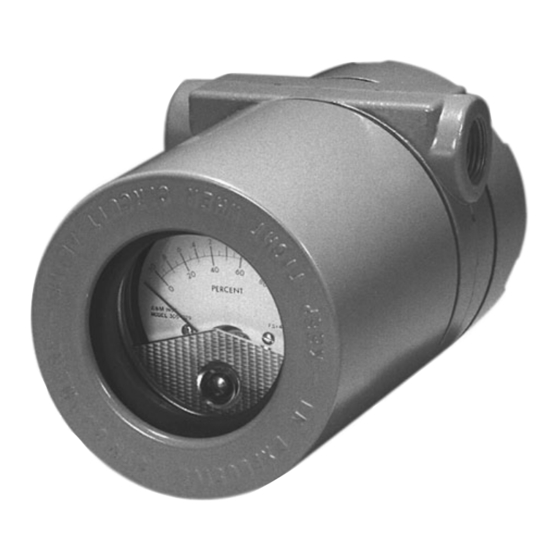
MODEL 1181pH/ORP SECTION 6.0 PARTS LIST SECTION 6.0 PARTS LIST 6.1 GENERAL. Following are the parts list and illustrations for identifying the parts and assemblies of the Model 1181 pH and 1181 ORP Two-Wire Transmitters FIGURE 6-1. Model 1181 pH/ORP Two-wire Transmitters... - Page 45 MODEL 1181pH/ORP SECTION 6.0 PARTS LIST TABLE 6-1. Parts List for Figure 6-1. Item Part Number Description 3002425 Cover (Blind) 2002604 O-Ring Kit Consists of: 2 ea. 9550136 O-Ring 2002528 Housing includes zero and span adjusting screws 2002598 Zero/span Screwkit 22795-02 Transmitter, PCB Blind/Analog 22795-03...
-
Page 46: Transducer Pcb (Part No. 22797-00/01 )
MODEL 1181pH/ORP SECTION 6.0 PARTS LIST FIGURE 6-2. Transducer PCB (Part No. 22797-00/01) Reference Designator Description Reference Fig. 6-2 Transducer PCB Designator Description 903994* 845K 0.1, 100WV 249K (pH) / 140K (ORP) 0.1, 100WV 0.01, 500V Ceramic 0.1, 100WV 249K 1N4933 121 (pH) / 143K (ORP) 1N4933... -
Page 47: Power Pcb (Part No. 22796-00)
MODEL 1181pH/ORP SECTION 6.0 PARTS LIST FIGURE 6-3. Power PCB (Part No. 22796-00) Reference Designator Description Reference Fig. 6-3 Power PCB Designator Description CD4047AE 0.01 100V Ceramic 30.1K 0.01 500V Ceramic 0.47 200K 100 Picofarads 100V Ceramic 100K Zero Pot 5K Span Pot 100 Picofarads 100V Ceramic 9080066... -
Page 48: Transmitter Pcb (Part No. 22795-00)
MODEL 1181pH/ORP SECTION 6.0 PARTS LIST FIGURE 6-4. Transmitter PCB (Part No. 22795-00) Reference Designator Description Reference Fig. 6-2 Transmitter PCB Designator Description 1CL7611DCPA (9030042*) 162K 0.01 500V Ceramic 0.01 500V Ceramic 1N4003 100K CR10 1N4003 165K CR11 1N4003 49.9 ±1%, 1W 2N5087 MPS5010A 92PU51A or 2N6727... -
Page 49: Return Of Material
Model 1181pH/ORP SECTION 7.0 RETURN OF MATERIAL SECTION 7.0 RETURN OF MATERIAL 7.1 GENERAL. 7.3 NON-WARRANTY REPAIR. To expedite the repair and return of instruments, proper The following is the procedure for returning for repair communication between the customer and the factory instruments that are no longer under warranty: is important. - Page 51 NESS FOR PARTICULAR PURPOSE, OR ANY OTHER MATTER WITH RESPECT TO ANY OF THE GOODS OR SERVICES. RETURN OF MATERIAL Material returned for repair, whether in or out of warranty, should be shipped prepaid to: Emerson Process Management Liquid Division 2400 Barranca Parkway...
- Page 52 The right people, the right answers, right now. ON-LINE ORDERING NOW AVAILABLE ON OUR WEB SITE http://www.raihome.com Credit Cards for U.S. Purchases Only. Emerson Process Management Liquid Division 2400 Barranca Parkway Irvine, CA 92606 USA Tel: (949) 757-8500 Fax: (949) 474-7250 http://www.raihome.com...
Need help?
Do you have a question about the Rosemount 1181pH TRANSMITTER and is the answer not in the manual?
Questions and answers