Emerson FloBoss 107 Instruction Manual
Flow manager
Hide thumbs
Also See for FloBoss 107:
- User manual (64 pages) ,
- Site considerations for equipment installation, grounding, and wiring manual (42 pages) ,
- Instruction manual (118 pages)
Table of Contents
Advertisement
Quick Links
Download this manual
See also:
User Manual
Advertisement
Table of Contents
Troubleshooting

Related Manuals for Emerson FloBoss 107


Summary of Contents for Emerson FloBoss 107
- Page 1 Part Number D301232X012 Form Number A6206 June 2017 ™ FloBoss 107 Flow Manager Instruction Manual Remote Automation Solutions...
- Page 2 FloBoss 107 Instruction Manual Revision Tracking Sheet June 2017 This manual may be revised periodically to incorporate new or updated information. The revision date of each page appears at the bottom of the page opposite the page number. A change in revision date to any page also changes the date of the manual that appears on the front cover.
-
Page 3: Table Of Contents
FloBoss 107 Instruction Manual Contents Chapter 1 – General Information Scope of Manual ..........................1-2 FloBoss 107 Overview ........................1-2 Hardware ............................1-5 1.3.1 Processor and Memory ....................1-6 1.3.2 Backplane ........................1-6 1.3.3 Expansion Rack .......................1-6 1.3.4 Central Processing Unit (CPU) ..................1-6 1.3.5 Battery and Super-capacitor ....................1-8 1.3.6... - Page 4 Installing the FloBoss 107 and Expansion Rack ................2-7 2.2.1 Required Tools ......................... 2-7 2.2.2 Installing the FloBoss 107 without an Expansion Rack ........... 2-7 2.2.3 Installing the FloBoss with an Expansion Rack ............... 2-8 2.2.4 Removing an Expansion Rack ..................2-10 2.2.5...
- Page 5 FloBoss 107 Instruction Manual 4.18 IEC 62591 Module........................4-27 4.18.1 Wiring the IEC 62591 Module ..................4-28 4.19 Additional Technical Information ....................4-28 Chapter 5 – Communications Communications Overview ......................5-1 Installing/Removing a Communication Module ................5-5 Wiring the Local Operator Interface (LOI) Port ................5-5 5.3.1...
- Page 6 FloBoss 107 Instruction Manual 7.4.7 Troubleshooting Pulse Inputs ..................7-13 7.4.8 Troubleshooting RTD Inputs ..................7-13 7.4.9 Troubleshooting the Multi-Variable Sensor (MVS) ............7-15 7.4.10 Troubleshooting the Enhanced Comm Module (ECM) ..........7-16 7.4.11 Troubleshooting the Dual Variable Sensor (DVS) ............7-16 7.4.12 Troubleshooting the Pressure Module (PIM) ..............
-
Page 7: Chapter 1 - General Information
This manual describes the FloBoss 107 Flow Manager (“FB107”), part of the family of FloBoss flow computers manufactured by Remote Automation Solutions, a division of Emerson Process Management. For information about the software you use to configure the FB107, refer to ™... -
Page 8: Scope Of Manual
FloBoss 107 Instruction Manual This chapter provides an overview of the FB107 and its components. Scope of Manual This manual contains the following chapters: Chapter 1 Provides an overview of the hardware and firmware General Information for the FB107 base unit and the expansion rack. - Page 9 Slot 3 = I/O or MVS module Slot 2 = I/O, MVS module, or COM module (COM2) Slot 1 = I/O, MVS, or COM module (COM3) Wire Channel Cover Display Connector Integral Sensor Connector Figure 1-1. FloBoss 107 Base Unit Revised June-2017 General Information...
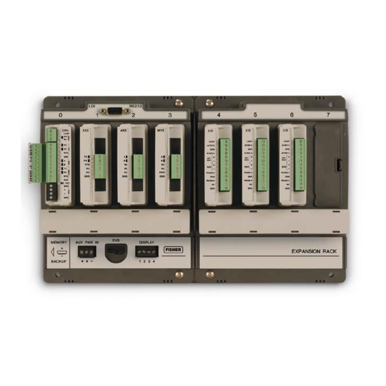
- Page 10 FloBoss 107 Instruction Manual Slot 4 = I/O or MVS module Slot 5 = I/O or MVS module Connects to FloBoss 107 base unit Slot 7 = I/O or MVS module Slot 6 = I/O or MVS module Wire Channel Cover Figure 1-2.
-
Page 11: Hardware
FloBoss 107 Instruction Manual Figure 1-3. FloBoss 107 with Expansion Rack The FB107 provides the following components and features: 32-bit processor board, inter-connect board, and backplane board. Central processing unit (CPU). Field-upgradeable 2 MB flash ROM (read only memory). -
Page 12: Processor And Memory
FloBoss 107 Instruction Manual The FB107 base unit has four slots. Slot 0 is reserved for the CPU module, which provides three communication ports, an RTD, power input, loop power output, system variables, and optional 6 points of I/O. Slots 1 and 2 can each contain one communication module. Slots 1, 2, and 3 can contain input/outputs (I/O), MVS, and application modules. - Page 13 FloBoss 107 Instruction Manual EIA-232 (RS-232) communications (COM2). Boot Flash – System initialization and diagnostics. SRAM (static random access memory) with battery backup – Data logs and configuration. Flash ROM (Read-only memory) – Firmware image. 32-bit microprocessor and the real-time operating system (RTOS) provide both hardware and software memory protection.
-
Page 14: Battery And Super-Capacitor
FloBoss 107 Instruction Manual 1.3.5 Battery and Super-capacitor A super capacitor (“super-cap”) and a coin type battery work together to provide backup power for the static RAM and the real-time clock. This helps to ensure retention of short and longer-term data, configuration, and operational integrity when the FB107 is not in service or is in storage. - Page 15 FloBoss 107 Instruction Manual Default values for the LOI port are: 19,200 baud rate, 8 data bits, 1 stop bit, no parity, group 1, and address 2. EIA-485 (RS-485) Serial COM1 provides EIA-485 (RS-485) serial communication protocols Communications with baud rates from 300 to 115.2 K...
-
Page 16: Built-In Resistance Thermal Device (Rtd)
FloBoss 107 Instruction Manual 1.3.8 Built-in Resistance Thermal Device (RTD) The FB107 supports a direct input from a resistance thermal device (RTD) sensor to measure flowing temperature. An RTD temperature probe typically mounts in a thermowell on the meter run. The RTD has a measurement range of 40 to 400°C (40 to 752°F). -
Page 17: Optional Communication Modules - Com3
FloBoss 107 Instruction Manual Adding an expansion rack to the FB107 base unit increases I/O by four slots for a total of six slots of I/O. The FB107 supports up to six I/O modules and one CPU I/O assembly. Other available I/O modules include the 8-point AI/DI, the 6-point... -
Page 18: Optional Multi-Variable Sensor (Mvs)
FloBoss 107 Instruction Manual COM3 can communicate with other devices using ROC or Modbus host and slave protocols. The firmware can automatically detect ROC or Modbus slave protocols. Note: See Chapter 5, Communications, for more information on FB107 communication modules. -
Page 19: Optional Lcd Touchpad
FloBoss 107 Instruction Manual Figure 1-5. Polycarbonate enclosure with a DVS module Figure 1-6. Steel enclosure with a PIM module 1.3.16 Optional LCD Touchpad The optional LCD Touchpad provides an external user interface to the process and operational information contained in the FB107. Use the... -
Page 20: Firmware
FloBoss 107 Instruction Manual transreflective touch-sensitive screen to view and change parameters and review historical and real-time data in the FB107. For further information, refer to product data sheet FloBoss 107 LCD Touchpad (FB107:LCD). Firmware The firmware makes extensive use of configuration parameters, which you manage using ROCLINK 800 software. -
Page 21: History Points
FloBoss 107 Instruction Manual Real-Time Operating The FB107 firmware uses a pre-emptive, multi-tasking, message-based System (RTOS) real-time operating system (RTOS). Tasks are assigned priorities and, at any given time, the operating system determines which task will run. For instance, if a lower priority task is executing and a higher priority... -
Page 22: Alarm Log
FloBoss 107 Instruction Manual Extended History archiving provides a monitoring resolution for the FB107 that is similar to a chart recorder. You can configure Extended History to archive up to 25 history points with archiving intervals at 1, 2, 3, 4, 5, 10, 12, 15, 20, 30, or 60 second or minute intervals. -
Page 23: Event Log
FloBoss 107 Instruction Manual Note: ROCLINK 800 does not store alarm logs to the flash ROM when you select the Save Configuration function. The alarm log operates in a circular fashion with new entries overwriting the oldest entry when the buffer is full. The alarm log provides an audit history trail of past alarms. -
Page 24: I/O Database
FloBoss 107 Instruction Manual can configure security protection on COM1, COM2, and COM3, but this security is disabled by default. 1.4.5 I/O Database The I/O database contains the I/O points the operating system firmware supports, including the system analog inputs and variables, Multi- Variable Sensor (MVS) values, communications, and smart application modules. -
Page 25: Spontaneous-Report-By-Exception (Srbx) Alarming
FloBoss 107 Instruction Manual 1.4.8 Spontaneous-Report-By-Exception (SRBX) Alarming The SRBX functionality allows you to set up a communications port that enables the FB107 to contact the host computer when specified alarm conditions exist. To configure SRBX alarming, each communications port must have the SRBX parameter enabled, each point must have the alarming parameter enabled, and points must have an SRBX parameter (SRBX on Set, SRBX on Clear, or SRBX on Set &... -
Page 26: User C Programs
FloBoss 107 Instruction Manual ROC protocol supports serial communications to local or remote devices, such as a host computer. An FB107 can act as a Modbus host or slave device using either Remote Terminal Unit (RTU) or American Standard Code for Information Interchange (ASCII) modes. - Page 27 FloBoss 107 Instruction Manual Remote configuration is possible from a host computer using a serial communications line. You can duplicate configurations and save them to a disk. In addition to creating a backup, this feature is useful when you are similarly configuring multiple FB107s for the first time, or when you need to make configuration changes off-line.
-
Page 28: Product Electronics
Board temperature For information on configuring alarms and System AI points, refer to Chapter 7 in the ROCLINK 800 Configuration Software User Manual (for FloBoss 107) (Form A6217). 1.6.3 Automatic Self Tests The FB107 becomes active when input power with the proper polarity and startup voltage (typically set greater than 8.0 volts) is applied to the... -
Page 29: Low Power Mode
FloBoss 107 Instruction Manual operational). The battery and logical voltage tests ensure that the FB107 is operating in the optimum mode. The software arms the watchdog timer every scan period. If the timer is not armed in 6 seconds, the software automatically resets. -
Page 30: Security Gateway
FloBoss 107 Instruction Manual input, which is sampled and linearized once per second, comes from an RTD probe. AGA3 calculations conform to the methods described in American Gas Association Report No. 3, Orifice Metering of Natural Gas and Other Related Hydrocarbon Fluids. Based on the second and third editions, the calculation method is 1992 AGA3. -
Page 31: Additional Technical Information
Table 1-2. Additional Technical Information Name Form Number Part Number ROCLINK 800 Configuration Software User Manual (for FloBoss 107) A6217 D301249X012 FloBoss 107 Flow Manager FB107 D301233X012... - Page 32 FloBoss 107 Instruction Manual [This page is intentionally left blank.] 1-26 General Information Revised June-2017...
-
Page 33: Chapter 2 - Installation And Use
Installing the FloBoss 107 and Expansion Rack ........ 2-7 2.2.1 Required Tools ..............2-7 2.2.2 Installing the FloBoss 107 without an Expansion Rack ..2-7 2.2.3 Installing the FloBoss with an Expansion Rack..... 2-8 2.2.4 Removing an Expansion Rack ..........2-10 2.2.5... -
Page 34: Site Requirements
FloBoss 107 Instruction Manual : In salt spray environments, it is especially important to ensure that Note the enclosure, including all entry and exit points, is sealed properly. The FB107 is designed to operate over a 40 to 75°C (40 to 167°F) temperature range. -
Page 35: Side And Front View Of Floboss 107 Base Unit
FloBoss 107 Instruction Manual 158.0 6.22 127.0 [ 0.19 4X Ø4.8 [ 5.00 134.4 15.5 5.29 ] 0.61 Figure 2-1. Side and Front View of FloBoss 107 Base Unit Figure 2-2. FloBoss 107 and Expansion Rack Revised June-2017 Installation and Use... -
Page 36: Compliance With Hazardous Area Standards
FloBoss 107 Instruction Manual 2.1.3 Compliance with Hazardous Area Standards The FB107 has approval for Class I Division 2 Groups A, B, C and D. Class, Division, and Group are defined as: Class defines the general nature of the hazardous material in the surrounding atmosphere. -
Page 37: Grounding Installation Requirements
FloBoss 107 Instruction Manual Figure 2-3. Power Connection on Base Unit Table 2-1. Power Connections Label Function Connection to Power Source Connection to Power Source – Ground The FB107 accepts input voltages from 8.0 volts to 30 volts at the PWR (IN+ / IN) terminals on the CPU. -
Page 38: I/O Wiring Requirements
FloBoss 107 Instruction Manual conductor should have a resistance of 1 ohm or less between the FB107 enclosure ground and the earth ground rod or grid. The recommended cable for I/O signal wiring is an insulated, shielded, twisted-pair. The twisted pair and the shielding minimize signal errors caused by EMI (electromagnetic interference), RFI (radio frequency interference), and transients. -
Page 39: Installing The Floboss 107 And Expansion Rack
Flat blade screwdriver, size 2.5 mm (0.1 inch). Flat blade screwdriver, large. 2.2.2 Installing the FloBoss 107 without an Expansion Rack To install the FB107 base unit without the expansion rack: Using the four holes on the FB107 base unit, mark the points at which the base unit should attach to the wall (refer to Figure 2-4). -
Page 40: Installing The Floboss With An Expansion Rack
FloBoss 107 Instruction Manual 195.1 [ 7.68 165.1 6.50 127.0 5.00 Plate mounting Holes Attachment posts Figure 2-4. Adapter Plate (FB107 Base Unit) To install the FB107 base unit to the FS1ADP-1 adapter plate: Place the unpowered base unit over the attachment posts. -
Page 41: Expansion Rack
FloBoss 107 Instruction Manual Align and gently press together the left edge of the expansion rack with the right edge of the base unit. Ensure that the connectors fit together. Using the four holes on the expansion rack, mark the points at which the expansion rack should attach to the wall. -
Page 42: Removing An Expansion Rack
FloBoss 107 Instruction Manual Slide the base unit to the right. Note: You should feel the retaining clips attach to the back of the base unit and the attachment posts should appear in the right- most holes on the base unit’s plastic housing. -
Page 43: Removing And Installing Module Slot Covers
FloBoss 107 Instruction Manual 2.2.5 Removing and Installing Module Slot Covers Before you insert an I/O, MVS, application, or communication module, you must remove the cover over the empty module slots in which you intend to install the modules. To avoid circuit damage when working inside the unit, use... -
Page 44: Memory Backup Battery
FloBoss 107 Instruction Manual Memory Backup Battery A super capacitor (“super-cap”) and a coin type battery work together to provide backup power for the static RAM and the real-time clock. This helps to ensure retention of short and longer-term data, configuration, and operational integrity when the FB107 is not in service or is in storage. -
Page 45: Central Processor Unit (Cpu)
FloBoss 107 Instruction Manual Remove the battery by gently prying the battery from its terminals. Replace the battery by placing the battery positive-side up and gently pressing it into place. Slide the Memory Backup cover back over the battery. Restore power to the FB107. - Page 46 FloBoss 107 Instruction Manual A Loop power + B Power In + C Power In - D LOI Tx (Red) E LOI Rx (White) LOI RTS G Ground (Black) H RS-485 A RS-485 B RS-232 Tx K RS-232 Rx RS-232 RTS...
-
Page 47: Removing The Cpu Module
FloBoss 107 Instruction Manual 2.4.1 Removing the CPU Module Failure to exercise proper electrostatic discharge precautions (such Caution as wearing a grounded wrist strap) may reset the processor or damage electronic components, resulting in interrupted operations. When working on units located in a hazardous area (where explosive gases may be present), make sure the area is in a non-hazardous state before performing procedures. -
Page 48: Installing The Cpu Module
FloBoss 107 Instruction Manual 2.4.2 Installing the CPU Module Failure to exercise proper electrostatic discharge precautions (such Caution as wearing a grounded wrist strap) may reset the processor or damage electronic components, resulting in interrupted operations. When working on units located in a hazardous area (where explosive gases may be present), make sure the area is in a non-hazardous state before performing+ procedures. -
Page 49: Startup And Operation
Once startup is successful, it is necessary to configure the FB107 to meet the requirements of the application. Refer to the ROCLINK 800 Configuration Software User Manual (for FloBoss 107) (Form A6217) for procedures on configuring the FB107 and calibrating its I/O. Once you configure and calibrate the FB107, you can place it in operation. - Page 50 FloBoss 107 Instruction Manual During operation, you can monitor the FB107 to view or retrieve current and historical data either locally or remotely. You accomplish local monitoring using ROCLINK 800 on a PC connected through the LOI port. You accomplish remote monitoring by using ROCLINK 800 connected through the COM1 through COM3 ports.
-
Page 51: Chapter 3 - Power Connections
FloBoss 107 Instruction Manual Chapter 3 – Power Connections In This Chapter Power Input Descriptions ..............3-1 Determining Power Consumption............3-3 3.2.1 Summary ................3-6 Wiring Connections ................3-6 Wiring Power to the CPU Module............3-7 This chapter describes wiring with FB107 with power from a dc voltage source. - Page 52 FloBoss 107 Instruction Manual Take care to route power away from hazardous areas, sensitive monitoring devices, and radio equipment. Local and company codes generally provide guidelines for power installations. Rigorously follow all local and National Electrical Code (NEC) requirements for power installations.
-
Page 53: Determining Power Consumption
FloBoss 107 Instruction Manual Table 3-1. Input Terminal Block Connections Terminal Blocks Definition Volts DC PWR (IN + / IN –) Accepts up to 28 Volts dc nominal from an AC/DC converter 8 to 30 Volts dc or other 28 volts dc supply. - Page 54 FloBoss 107 Instruction Manual Valid for slot 7 only if a Comm module is installed in slot 1 Represents Base (Loop loading x Loading Factor) Table 3-3. Power Consumption Worksheet Power Total Power System Power (mW) Field Power (mW) Voltage...
- Page 55 FloBoss 107 Instruction Manual For example, let’s suppose the following module configuration for an eight-slot FB107: Add’l Valid Base Idle Max Active Loading Module Slots Module Description (No Load) (Full Load) Load Factor Power in mW CPU Isolated with I/O...
-
Page 56: Wiring Connections
FloBoss 107 Instruction Manual 3.2.1 Summary Using the worksheet, you can determine the day-to-day power requirements for your intended system as well as how much battery power you may require to maintain your system in the absence of external power. By downloading the Excel spreadsheet from SupportNet, you can then adjust your expectations and requirements to meet your FB107 power needs. -
Page 57: Wiring Power To The Cpu Module
FloBoss 107 Instruction Manual Wiring Power to the CPU Module Typically, you would use the AUX PWR IN connection on the FB107 base unit to power the FB107. Alternately, you can wire power directly into the CPU module. Loop Power + Output Power In + Power In –... - Page 58 FloBoss 107 Instruction Manual [This page is intentionally left blank.] Power Connections Revised June-2017...
-
Page 59: Chapter 4 - Inputs And Outputs
FloBoss 107 Instruction Manual Chapter 4 – Inputs and Outputs In This Chapter I/O Description ..................4-1 Installing a Module ................4-5 Removing a Module ................4-6 Wiring a Module.................. 4-7 Selecting the Type of I/O ..............4-7 Analog Inputs (AI) ................4-9 4.6.1... -
Page 60: Cpu Module
FloBoss 107 Instruction Manual channels have a removable plug-in terminal block for field wiring. You can order the expanded 6-point I/O as an: I/O assembly that mounts directly on the CPU module. I/O modules that mount in the I/O slots. -
Page 61: I/O Module
FloBoss 107 Instruction Manual : There are slight differences in the termination positions. Note Loop Output Power AI1+/DI1+ GND – (Common) AI2+/DI2+ AO+/DO1+ AO–/DO1– DO2+ DO2– PI1+/DI3+ GND – (Common) PI2+/DI4+ NC (No Connection) GND – (Common) Figure 4-1. I/O Module Table 4-1. - Page 62 FloBoss 107 Instruction Manual Termination I/O Type Number DO2+ DO2 PI1+/DI3+ GND – (Common) PI2+/DI4+ NC (No Connection) GND – (Common) A AI1+/DI1+ B GND – (Common) C AI2+/DI2+ D AO+/DO1+ E AO–/DO1– F DO2+ G DO2– H PI1+/DI3+ GND – (Common) J PI2+/DI4+ Figure 4-2.
-
Page 63: Installing A Module
FloBoss 107 Instruction Manual Table 4-2. I/O Terminations on the CPU Module’s Optional I/O Assembly Termination I/O Type Number AI1+/DI1+ GND – (Common) AI2+/DI2+ AO+/DO1+ AO-/DO1 DO2+ DO2 PI1+/DI3+ GND – (Common) PI2+/DI4+ Installing a Module All I/O modules for the FB107 are designed for ease of installation and removal. -
Page 64: Removing A Module
FloBoss 107 Instruction Manual Wire the I/O module. Refer to Section 4.4, Wiring a Module. Replace the wire channel cover. Never connect the sheath surrounding shielded wiring to a signal Caution ground terminal or to the common terminal of an I/O module or CPU I/O assembly. -
Page 65: Wiring A Module
FloBoss 107 Instruction Manual : Once you remove a module, always be sure to replace its cover. Note This protects the module slot from dust and prevents damage to the cover’s locking mechanism. Wiring a Module I/O wiring requirements are site and application dependent. Local, state, or NEC requirements determine the I/O wiring installation methods. - Page 66 FloBoss 107 Instruction Manual : Figure 4-5 shows the default values for an I/O module. Note Figure 4-4. FloBoss 107 ROCLINK 800 User Interface Click the I/O Setup tab. Figure 4-5. I/O Setup Select the types of I/O to use.
-
Page 67: Analog Inputs (Ai)
FloBoss 107 Instruction Manual If you select analog inputs (AI), select the 250 Ohm Resistor Installed option if you want the analog input in the current loop mode. Click Apply. Make sure you select the I/O types before you configure the I/O Note: using ROCLINK 800. -
Page 68: Loop Output Power For The Cpu
FloBoss 107 Instruction Manual The I/O module only supports 24 volts dc loop output power. The CPU module’s I/O assembly uses the CPU’s loop power output and ground connections. The intent of the loop output power is to power devices (such as... -
Page 69: 8-Point Analog Input/Digital Input (Ai/Di) Module
FloBoss 107 Instruction Manual INTERNALLY POWERED ANALOG DEVICE Figure 4-7. Loop Output Power for the I/O Module 8-Point Analog Input/Digital Input (AI/DI) Module The 8-point analog input/digital input (AI/DI) module provides eight user-selectable analog or digital inputs. The Analog inputs (AI) monitor current loop and voltage input devices. -
Page 70: Di Wiring
FloBoss 107 Instruction Manual DI channel, you can use ROCLINK 800 to configure the channel as necessary. CONTACT-CLOSURE DEVICE EXTERNALLY POWERED DISCRETE DEVICE OPEN DRAIN TYPE OPEN COLLECTOR DEVICE EXTERNALLY POWERED DISCRETE DEVICE Figure 4-8. DI Wiring INTERNALLY POWERED ANALOG DEVICE Figure 4-9. -
Page 71: Analog Outputs (Ao)
FloBoss 107 Instruction Manual EXTERNALLY EXTERNAL POWERED POWER ANALOG DEVICE Figure 4-10. AI Wiring (External Power) Analog Outputs (AO) The analog outputs (AO) provide a 4 to 20 mA current source output for powering analog loop devices. Analog outputs are analog signals the FB107 generates to regulate equipment, such as control valves or any device requiring analog control. -
Page 72: Discrete Inputs (Di)
FloBoss 107 Instruction Manual INTERNALLY POWERED Figure 4-11. Analog Output Wiring (on CPU Module) Discrete Inputs (DI) The discrete input (DI) monitors the status of relays, open collector/open drain type solid-state switches, and other two-state devices. Discrete inputs come from relays, switches, and other devices, which generate an on/off, open/close, or high/low signal. -
Page 73: Wiring The Discrete Inputs
FloBoss 107 Instruction Manual Select DI as the I/O Type for the selectable pulse inputs/discrete Note: inputs when you configure it for use as a discrete input. Refer to Figure 4-5. 4.9.1 Wiring the Discrete Inputs The terminals provided on the CPU module for connecting the DI wiring are shown in Figure 4-12. -
Page 74: Wiring The Discrete Outputs
FloBoss 107 Instruction Manual DO functions include: Sustained discrete outputs. Momentary discrete outputs. Toggled output. Time duration output. The discrete output channel is a normally-open, FET switch. The discrete output is a solid-state switch enabled by individual signals from the processor I/O lines and capable of handling 50 Volts dc at 0.2 A... -
Page 75: 4.11 Discrete Outputs Relay (Dor) Module
FloBoss 107 Instruction Manual LOW SIDE SWITCH POWER SWITCHED SUPPLY DEVICE Figure 4-13. Discrete Output Wiring - Low Side Switch (on CPU Module) HIGH SIDE SWITCH POWER SWITCHED SUPPLY DEVICE Figure 4-14. Discrete Output Wiring - High Side Switch (on CPU Module) 4.11 Discrete Outputs Relay (DOR) Module... -
Page 76: Wiring The Discrete Output Relays
FloBoss 107 Instruction Manual 16. Using ROCLINK 800 software, you can configure the module as latched, toggled, momentary, or Timed Duration Outputs (TDO). The discrete output channel is a normally open contact. The discrete output is a relay switch enabled by individual signals from the processor I/O lines and capable of handling 30 Volts dc at 1.0 A maximum. -
Page 77: Pulse Inputs (Pi)
FloBoss 107 Instruction Manual LOW SIDE SWITCH POWER SWITCHED DO2-DO6 SUPPLY DEVICE Figure 4-16. Discrete Output Relay Module Wiring (Low Side Switch) 4.12 Pulse Inputs (PI) Pulse inputs (PI) processes signals from pulse-generating devices and provide a calculated rate or an accumulated total over a configured period. -
Page 78: 4.13 Application (App 485) Module
FloBoss 107 Instruction Manual To use the channel as a pulse input, connect the + and GND field wires to terminals PI1+ or PI2+ and GND. You can induce ground loops by tying commons from various modules Caution together. INTERNALLY POWERED Figure 4-17. - Page 79 FloBoss 107 Instruction Manual 120 OHM TERMINATION RESISTOR USER SUPPLIED FIELD DEVICE EXTERNAL POWER Figure 4-18. Application Module Wiring to Single Field Device : To provide internal power to a field device, connect the positive Note wire to the PWR connection and the negative wire to the GND connection on the APP485 module.
-
Page 80: 4.14 Resistance Temperature Detector (Rtd) Input
FloBoss 107 Instruction Manual 4.14 Resistance Temperature Detector (RTD) Input The resistance temperature detector (RTD) on the CPU monitors the temperature signal from an RTD source. The RTD can accommodate input from a three- or four-wire RTD source. The RTD has a measurement range of 40 to 400°C (40 to 752°F). -
Page 81: 4.15 6-Point Ao/Do Module
FloBoss 107 Instruction Manual Table 4-3. RTD Wiring Terminal Wiring Color Designation 4-Wire RTD 3-Wire RTD Signal source current positive input + RTD + RTD + RTD – RTD – RTD – RTD White White Negative ground return reference GND jumper to –... -
Page 82: Wiring The 6-Point Ao/Do Module
FloBoss 107 Instruction Manual 4.15.1 Wiring the 6-Point AO/DO Module Configure all AO/DO points in ROCLINK before connecting any wiring. Caution Failure to do so may result in physical damage to the I/O board. Figures 4-21 through 4-24 show a variety of wiring scenarios. -
Page 83: Wiring The Hart Module
FloBoss 107 Instruction Manual channel. A channel set as an input can be configured for use in point-to- point or multi-drop mode. A channel set as an output can be configured for use in point-point mode only. In multi-drop mode, as many as five HART devices can be connected (in parallel) to each channel. -
Page 84: 4.17 Resistance Temperature Detector (Rtd) Module
FloBoss 107 Instruction Manual Figure 4-27. HART Output Wiring 4.17 Resistance Temperature Detector (RTD) Module The 3-channel Resistance Temperature Detector (RTD) module enables the FB107 to monitor various RTD sensors. An FB107 can support up to six RTD modules. The module monitors the temperature signal from an RTD within a fixed range. -
Page 85: 4.18 Iec 62591 Module
FloBoss 107 Instruction Manual Figure 4-28. 2-Wire Connection Wiring Figure 4-29. 3-Wire Connection Wiring Figure 4-30. 4-Wire Connection Wiring 4.18 IEC 62591 Module The IEC 62591 module, when installed in a FB107 and wired to a Smart Wireless Field Link, enables you to communicate with a network of up to 25 WirelessHART devices installed in the field. -
Page 86: Wiring The Iec 62591 Module
FloBoss 107 Instruction Manual 4.18.1 Wiring the IEC 62591 Module Figure 4-31 shows the IEC 62591 module wired to a Smart Wireless Field Link. Figure 4-31. FB107 IEC 62591 Module Power and Data Wiring to Field Link 4.19 Additional Technical Information Refer to the following documents (available at www.EmersonProcess.com/Remote) for additional and most-current... -
Page 87: Chapter 5 - Communications
FloBoss 107 Instruction Manual Chapter 5 – Communications In This Chapter Communications Overview ..............5-1 Installing/Removing a Communication Module ........5-5 Wiring the Local Operator Interface (LOI) Port ........5-5 5.3.1 Using the LOI ................ 5-6 Wiring EIA-485 (RS-485) Communications ........5-6 Wiring EIA-232 (RS-232) Communications ........ -
Page 88: Eia-232
FloBoss 107 Instruction Manual Figure 5-1. EIA-232 (RS-232) Communication Figure 5-2. EIA-485 (RS-485) Communication Module Module Communications Revised June-2017... - Page 89 FloBoss 107 Instruction Manual Local Port EIA-232 (RS-232) COM1 EIA-485 (RS-485) COM2 Default EIA-232 (RS-232) Figure 5-3. CPU The FB107 supports up to four communication ports: LOI, COM1, COM2, and COM3: Local Operator Interface (RS-232C) Located on the CPU and labeled LOI (see Figure 5-3), the LOI port provides asynchronous serial communications, with DB9 connector.
- Page 90 FloBoss 107 Instruction Manual EIA-232 (RS-232) Located on the CPU and labeled COM2 (see Figure 5-3), the COM2 port provides the default for serial communications. It is the standard for single-ended data transmission over distances of up to 15 m (50 ft).
-
Page 91: Installing/Removing A Communication Module
FloBoss 107 Instruction Manual Installing/Removing a Communication Module All FB107 modules are designed for ease of installation and removal. Refer to Installing a Module, Removing a Module, and Wiring a Module in Chapter 4, Inputs/Outputs and RTD Inputs, for specific instructions. -
Page 92: 5.3.1 Using The Loi
FloBoss 107 Instruction Manual LEDs display the RX (receive) and TX (transmit) signals for EIA-232 (RS-232) communications. The LOI supports ROC or Modbus slave protocol communications. The LOI also supports the log-on security feature of the FB107, if you enable security on the LOI using ROCLINK 800. -
Page 93: Wiring Eia-232 (Rs-232) Communications
FloBoss 107 Instruction Manual EIA-485 (RS-485) supports the log-on security feature of the FB107 if you enable security on the communication port using ROCLINK 800. LEDs display the A (transmit/receive+) and B (transmit/receive ) signals for EIA-485 (RS-485) communications. Default values for the EIA-485 (RS-485) communication module are: 19,200 baud rate, 8 data bits, 1 stop bit, no parity, 10 millisecond key-on delay, and 10 millisecond key-off delay. -
Page 94: Liquid Crystal Display (Lcd) Touchpad
FloBoss 107 Instruction Manual The EIA-232 (RS-232) default values are: 19,200 baud rate, 8 bits, 1 stop bit, no parity, 10 millisecond key-on delay, and 10 millisecond key-off delay. The maximum baud rate is 115.2 Kbps. EIA-232 (RS-232) supports the log-on security feature of the FB107 if you enable the security on the communication port using ROCLINK 800. -
Page 95: Enhanced Communication Module (Ecm)
FloBoss 107 Instruction Manual The LCD default values are: 19,200 baud rate, 8 data bits, 1 stop bit, no parity. The maximum baud rate is 57.6 Kbps. Figure 5-5. Display Connection on Base Unit Table 5-4. LCD Connections Label Function... -
Page 96: Activating The Usb Port
FloBoss 107 Instruction Manual Figure 5-6. Enhanced Communication Module (ECM) 5.7.1 Activating the USB Port The ECM includes a USB port that provides local operator interface (LOI) functions when the configuring laptop may not have a serial (RS- 232) port. -
Page 97: Device Manager
FloBoss 107 Instruction Manual Figure 5-7. Device Manager Select Other devices and double-click ECM USB Device. The ECM USB Device Properties screen displays. Figure 5-8. ECM USB Device Properties Revised June-2017 Communications 5-11... -
Page 98: Update Browser Software
FloBoss 107 Instruction Manual Select the Update Driver button. Figure 5-9. Update Browser Software Select Browse my computer for driver software. Figure 5-10. Update Browser Software 5-12 Communications Revised June-2017... - Page 99 FloBoss 107 Instruction Manual Select the Browse button and navigate to the ROCKLINK800 program folder. Make sure the Include Subfolders checkbox is selected and click Next. Figure 5-11. Windows Security Windows finds the ECM_USB_DRIVER.inf file, begins the installation process, and a warning message displays. Select Install this driver software anyway.
-
Page 100: Pop-Up Menu
FloBoss 107 Instruction Manual Figure 5-13. Confirmation Screen Verifying the After you install the ECM, you should verify the installation. To verify Installation that you have correctly installed the ECM, connect to ROCLINK 800 but do not connect to a device. -
Page 101: Dial-Up Modem Module
FloBoss 107 Instruction Manual Comm Port options Figure 5-15. Communication Parameters Click Refresh Comm Port List. Then click on the Comm Port field. If you see ECM USB Device (see Figure 5-13) as one of the comm port selections, the module is correctly installed. If you want to use it, select it, click Apply, and then click Connect. -
Page 102: Network Radio Module (Nrm)
FloBoss 107 Instruction Manual The module has removable terminal blocks for convenient wiring and servicing. The terminal blocks can accommodate size 16 to 24 American Wire Gauge (AWG). The module uses a standard “tip and ring” PSTN wiring schema. Figure 5-16. Dial-Up Modem Module 5.9 Network Radio Module (NRM) -
Page 103: Installing The Nrm
FloBoss 107 Instruction Manual Figure 5-17. Network Radio Module 5.9.1 Installing the NRM The NRM is designed to be plug-and-play and requires no wiring. The NRM can be installed in slot 1 or 2 in the FB107. Depending on the enclosure you choose to surround the node and protect it from the environment, you may need additional cabling between the antenna and the connection on the module itself. - Page 104 FloBoss 107 Instruction Manual [This page is intentionally left blank.] 5-18 Communications Revised June-2017...
-
Page 105: Chapter 6 - Sensors And Transducers
FloBoss 107 Instruction Manual Chapter 6 – Sensors and Transducers In This Chapter Multi-Variable Sensor (MVS) Module Overview ......... 6-1 6.1.1 Installing/Removing an MVS Module ........6-4 6.1.2 Configuring a Multi-drop MVS Module Setup ......6-4 6.1.3 Lightning Protection ............... 6-6 Dual Variable Sensor (DVS) Overview .......... - Page 106 FloBoss 107 Instruction Manual Note: You set values for MVS transmitters using ROCLINK 800’s MVS Sensor screen (Configure > I/O > MVS Sensor). Once you set a unique address for each transmitter, connect the transmitters in a multi-drop (or “daisy-chair”) configuration (see Figure 6-2).
- Page 107 FloBoss 107 Instruction Manual The 4088B is Remote Automation Solutions’ latest transmitter 4088B Transmitter product. Designed as a drop-in replacement for the MVS205 sensor, you use ROCLINK 800 to configure and (if necessary) calibrate the module. Refer to the following figure to correctly wire up to four 4088B transmitters to the MVS module.
-
Page 108: Installing/Removing An Mvs Module
FloBoss 107 Instruction Manual The interface circuit allows the transmitter to connect to and communicate with an FB107 using a serial 2-wire EIA-485 (RS- 485) connection. 6.1.1 Installing/Removing an MVS Module All FB107 modules are designed for ease of installation and removal. - Page 109 FloBoss 107 Instruction Manual Figure 6-2 shows a terminating resistor—typically a 121 Ω Note: customer-supplied resistor—on the last transmitter in the multi-drop. This resistor correctly terminates the multi- drop configuration. To configure a multi-drop MVS transmitter setup, you connect each transmitter to the FB107 and configure it individually.
-
Page 110: Lightning Protection
FloBoss 107 Instruction Manual on the MVS module. The wires should be size 16 to 24 AWG and a maximum length of 1220 meters (4000 feet). Note: Do not reverse the power wires. Always make these connections after you remove power from the FB107. -
Page 111: Dual Variable Sensor (Dvs) Overview
FloBoss 107 Instruction Manual Lightning Protection Corporation PO Box 6086 Santa Barbara, CA 93160 Telephone: 1-800-317-4043 http://www.lightningprotectioncor.com/ Dual Variable Sensor (DVS) Overview The DVS provides the FB107 with static pressure and differential pressure measurement for orifice flow calculations. Each FB107 supports one DVS. -
Page 112: Installing/Removing A Dvs
FloBoss 107 Instruction Manual this value and stores it in the designated AI point for use by other functions. If an update does not occur within the one-second interval, the FB107 re-initializes the sensor. If the DVS does not response to the re-initialization, a point fail alarm appears on the alarm log. -
Page 113: Physically Connecting A Dvs
FloBoss 107 Instruction Manual Figure 6-6. FB107 Graphical Interface for DVS The tabs—General, I/O Points, and Diagnostic—provide information (mostly read-only) on the DVS. 6.2.2 Physically Connecting a DVS Run piping from the meter run to the DVS. Both the static and differential pressures attach to female ¼-18 NPT connections on... -
Page 114: Configuring A Dvs
FloBoss 107 Instruction Manual 6.2.3 Configuring a DVS The DVS provides the FB107 with an analog input. To configure the input, access the I/O Points tab on the FB107 graphical interface and click on the configuration button. ROCLINK 800 displays an Analog Input screen. -
Page 115: Installing/Removing A Pressure Module
FloBoss 107 Instruction Manual PIM Module Figure 6-8. FB107 Enclosure with Optional LCD and Pressure Module The Pressure module (PIM) provides the FB107 with pressure inputs and pulse counts for AGA7 flow calculations with AGA8 compressibility. Each FB107 supports one PIM, which can have up to two pressure transducers. - Page 116 FloBoss 107 Instruction Manual The Pressure module connects through the DVS connector on the FB107 base unit (see Figure 6-9. Integral Sensor Connector Figure 6-9. FB107 Base Unit, Integral Sensor Connector With the PIM module installed, you can start ROCLINK 800.
-
Page 117: Configuring A Pressure Module
FloBoss 107 Instruction Manual Figure 6-10. FB107 Graphical Interface for PIM The four tabs—General, Advanced, I/O Points, and Diagnostic— provide information (mostly read-only) on the Pressure module. 6.3.2 Configuring a Pressure Module The Pressure module provides the FB107 with an analog input (for pressure). -
Page 118: 6.4 Additional Technical Information
FloBoss 107 Instruction Manual Figure 6-11. Analog Input Refer to Section 7.2, Analog Input (AI) Configuration in the ROCLINK 800 Configuration Software User Manual (for FloBoss 107) (part D30nnnnX012) for complete instructions on using these screens to configure the AI. -
Page 119: Chapter 7 - Troubleshooting
FloBoss 107 Instruction Manual Chapter 7 – Troubleshooting In This Chapter General Guidelines ................7-1 Graphical User Interface (GUI) ............7-2 Checklists ................... 7-4 7.3.1 LEDs ..................7-4 7.3.2 Serial Communications ............7-4 7.3.3 Inputs/Outputs ............... 7-5 7.3.4 Preserving Configuration and Log Data ........ 7-6 7.3.5... -
Page 120: Graphical User Interface (Gui)
FloBoss 107 Instruction Manual Save the configuration and log data (refer to Section 7.3.4, Preserving Configuration and Log Data). Note the order in which you remove components. Note the orientation of the components before you alter or remove them. - Page 121 FloBoss 107 Instruction Manual Integrity Alert (Red) Alarm (Yellow) Figure 7-1. FB107 GUI The I in a red box indicates an integrity alert. The A in a yellow box indicates an alarm. This example screen shows a red integrity alert on the CPU module’s I/O assembly, and both an integrity alert and an alarm on...
-
Page 122: Checklists
FloBoss 107 Instruction Manual For more information on the FB107 GUI, refer to the ROCLINK 800 Configuration Software User Manual (for FloBoss 107) (part D301249X012). Checklists This section provides brief topical checklists. 7.3.1 LEDs If the LEDs do not display on the CPU or the modules: ... -
Page 123: Inputs/Outputs
FloBoss 107 Instruction Manual 7.3.3 Inputs/Outputs If you are experiencing troubles with an I/O point (analog input, analog output, discrete input, discrete output, pulse input, or RTD): Ensure that power is applied to the FB107. Verify the wiring connections at PWR+ and PWR. -
Page 124: Preserving Configuration And Log Data
FloBoss 107 Instruction Manual 7.3.4 Preserving Configuration and Log Data Before you power down the FB107 to repair or upgrade, to remove or add a component, or to troubleshoot, you should preserve the FB107 configuration and log data held in RAM. -
Page 125: Powering Up
FloBoss 107 Instruction Manual Use a cold start to restart without a portion of the configuration, log data, or programming that may be the trouble. To perform a cold start, open ROCLINK 800 software, connect to the FB107 and select ROC >... -
Page 126: Iec 62591 Module
FloBoss 107 Instruction Manual –40C –40F 84 100 0C 32F 150 130C 267F 200 267C 512F 250 408C 767F : These values are approximations only. Do not use these values to Note calibrate the device. Verify that the wiring to the RTD terminations is correct. Refer to Chapter 4, Input and Outputs. -
Page 127: Resetting The Fb107
FloBoss 107 Instruction Manual 7.4.1 Resetting the FB107 You reset the FB107 to perform a type of cold start that re-establishes a known operating point and loads the factory defaults (19,200 baud rate, 8 data bits, no parity, and 1 stop bit) into the communication ports. The reset (RST) switch is located on the CPU module, just above the RTD terminal block. -
Page 128: Troubleshooting Analog Inputs
FloBoss 107 Instruction Manual Select the configuration file you desire to restore. Click Download to restore the configuration. 7.4.3 Troubleshooting Analog Inputs Before you can determine if an analog input point is operating properly, you must first know its configuration. Table 7-1 shows typical configuration values for an analog input: Table 7-1. -
Page 129: Troubleshooting Analog Outputs
FloBoss 107 Instruction Manual 7.4.4 Troubleshooting Analog Outputs Multimeter Required PC running ROCLINK 800 software Equipment Failure to exercise proper electrostatic discharge precautions, such Caution as wearing a grounded wrist strap may reset the processor or damage electronic components, resulting in interrupted operations. -
Page 130: Troubleshooting Discrete Inputs
FloBoss 107 Instruction Manual 7.4.5 Troubleshooting Discrete Inputs Jumper wire Required PC running ROCLINK 800 software Equipment Failure to exercise proper electrostatic discharge precautions, such Caution as wearing a grounded wrist strap may reset the processor or damage electronic components, resulting in interrupted operations. -
Page 131: Troubleshooting Pulse Inputs
FloBoss 107 Instruction Manual Connect an ohm meter from the DO+ to the DO-. When the DO is off, the ohm meter should indicate an open circuit. Using ROCLINK 800, set the DO to the on state. Verify that the ohm meter indicates less than 10 ohms. - Page 132 FloBoss 107 Instruction Manual Failure to exercise proper electrostatic discharge precautions, such Caution as wearing a grounded wrist strap may reset the processor or damage electronic components, resulting in interrupted operations. Connect to ROCLINK 800. Select Configure > I/O > AI Points.
-
Page 133: Troubleshooting The Multi-Variable Sensor (Mvs)
FloBoss 107 Instruction Manual 7.4.9 Troubleshooting the Multi-Variable Sensor (MVS) The Multi-Variable Sensor is simple in operation, without user- serviceable parts. For repair or replacement, return the transmitter to your local sales representative. Pressure bottle Required PC running ROCLINK 800 software... -
Page 134: Troubleshooting The Enhanced Comm Module (Ecm)
FloBoss 107 Instruction Manual Resetting the MVS to If you are having difficulty communicating with an MVS transmitter, Factory Defaults reset the MVS to factory default settings. To restore factory default settings in an MVS: Connect the FB107 to a PC running ROCLINK 800. -
Page 135: Troubleshooting The Pressure Module (Pim)
FloBoss 107 Instruction Manual Bleed Bleed High Pressure Open Remains Close Close Operating Shutdown Sequence Shutdn2 Figure 7-3. DVS Depressurization Open the manifold according to manufacturer’s instructions. Apply pressure to the manifold or sensor bleed values and monitor the resulting values in ROCLINK 800. -
Page 136: Troubleshooting Ai/Di
FloBoss 107 Instruction Manual 7.4.13 Troubleshooting AI/DI This module provides eight AI or DI signals. Troubleshooting depends on whether you have selected AI or DI wiring. Multimeter Required Digitial voltmeter Equipment PC running ROCLINK 800 software Failure to exercise proper electrostatic discharge precautions, such... -
Page 137: Appendix A - Glossary
FloBoss 107 Instruction Manual Appendix A – Glossary Note: This is a generalized glossary of terms. Not all the terms may necessarily correspond to the particular device or software described in this manual. For that reason, the term “ROC” is used to identify all varieties of Remote Operations Controllers (including ROC800-Series, ROC800L, DL8000, FloBoss™... - Page 138 FloBoss 107 Instruction Manual (continued) COMM Communications port on a ROC used for host communications. . Note: On FloBoss 500-Series and FloBoss 407s, COMM1 is built-in for RS-232 serial communications. Comm Module Module that plugs into a ROC to provide a channel for communications via a specified communications protocol, such as EIA-422 (RS-422) or HART.
-
Page 139: Electromagnetic Interference
FloBoss 107 Instruction Manual (continued) DRTU A primary component of the Distributed RTU Network, consisting of a FB107 chassis housing a focused functionality CPU and a Network Radio module (NRM). The DRTU collects process variables from one or more wellheads and transmits the signals throughout the designed network. - Page 140 FloBoss 107 Instruction Manual (continued) Frequency Shift Keypad. Function Sequence Table, a type of user-written program in a high-level language designed by Emerson Process Management’s Flow Computer Division. Foot or feet. Ground Fault Analysis. Gigahertz, 10 cycles per second Electrical ground, such as used by the ROC’s power supply.
- Page 141 FloBoss 107 Instruction Manual Kilobytes. KiloHertz. Liquid Crystal Display. Local Display Panel, a display-only device that plugs into ROC300-Series units (via a parallel interface cable) used to access information stored in the ROC. Light-Emitting Diode. Logical Number The point number the ROC and ROC Plus protocols use for I/O point types are based on a physical input or output with a terminal location;...
- Page 142 CPU and a Network Radio module) provides a data collection point that wirelessly transmits data throughout the designed network. Network Radio module; a module used in both the FloBoss 107 and ROC00-Series based devices to wirelessly transmit information throughout the distributed RTU network.
- Page 143 FloBoss 107 Instruction Manual type of duplex. PSTN Public Switched Telephone Network. Process Temperature. Push-to-Talk signal. Pulse Transient variation of a signal whose value is normally constant. Pulse Interface A module that provides line pressure, auxiliary pressure, and pulse counts to a ROC.
- Page 144 FloBoss 107 Instruction Manual (continued) Script An uncompiled text file (such as keystrokes for a macro) that a program interprets in order to perform certain functions. Typically, the end user can easily create or edit scripts to customize the software.
- Page 145 FloBoss 107 Instruction Manual Index Wiring ............. 5-6, 5-7 Numerics Communication Modules COM3 ............1-11 250 Ohm Resistor Installed ......4-9 Communications 4088B Transmitter ..........6-3 485 ..............5-3 Built-in ............1-8 COM1 ............5-3 A ..............5-4, 5-7 COM2 ............5-4 Address COM3 ............
- Page 146 ........... 1-13 and Data Wiring to Field Link ....4-28 1-6. Steel enclosure with a PM module ..1-13 5-1. EIA-232 (RS-232 Communication 2-1. Side and Front View of FloBoss 107 Base Module ............. 5-2 Unit ............2-3 5-2. EIA-485 (RS-485 Communication 2-2.
- Page 147 7-2. MVS Depressurization ......7-16 Impedance 7-3. DVS Depressurization ......7-18 Grid ............... 2-5 Firmware ............1-14 Input/Output FloBoss 107 Flow Manager ......1-1 I/O ..............4-1 FloBoss 107 Flow Manager LCD User Installing Manual ............1-25 Batteries ............2-12 Flow Measurement .........
- Page 148 FloBoss 107 Instruction Manual Sleep Mode ..........1-23 Surge Protection ..........2-5 Memory ..............1-6 Troubleshooting ..........7-8 Memory Backup ......1-8, 2-12, 2-13 Wiring ............ 3-1, 3-7 Microprocessor ..........1-6 Preserving Configuration and Log Data ... 7-6 Min / Max Historical Log ......... 1-16 Pressure module (PM) ........
- Page 149 FloBoss 107 Instruction Manual Selecting Installing ............6-5 I/O Types ............4-7 Troubleshooting Set Back to Factory Defaults AI/DI ............7-19 MVS ............7-17 Analog Inputs ..........7-11 Site Requirements ..........2-2 Analog Outputs ........... 7-12 Sleep Mode ............. 1-23 Communiations ..........
- Page 150 FloBoss 107 Instruction Manual HART ............4-25 Loop Power Outputs ........4-9 I/O ..............3-6 Power ............ 3-1, 3-7 I/O Requirements ..........2-6 Pulse Inputs ..........4-19 I/O Wiring ............4-7 RTD Input ........... 4-22 LCD ...............5-8 Worksheets Local Operator Interface (LOI) Port ....5-5 Power ............
- Page 151 FloBoss 107 Instruction Manual [This page is intentionally left blank.] Revised June-2017 Index...
- Page 152 Emerson Automation Solutions Remote Automation Solutions Emerson FZE P.O. Box 17033 © 2006–2017 Remote Automation Solutions, a business unit of Emerson Automation Jebel Ali Free Zone – South 2 Solutions. All rights reserved. Dubai U.A.E. This publication is for informational purposes only. While every effort has been made to ensure...
Need help?
Do you have a question about the FloBoss 107 and is the answer not in the manual?
Questions and answers