Emerson 1057 Instruction Manual
Three-input intelligent analyzer
Hide thumbs
Also See for 1057:
- Instruction manual (66 pages) ,
- Quick start manual (24 pages) ,
- Quick start manual (36 pages)
Table of Contents

Related Manuals for Emerson 1057


Summary of Contents for Emerson 1057
- Page 1 Instruction Manual PN 51-1057/rev.C Model 1057 January 2010 THREE-INPUT INTELLIGENT ANALYZER...
- Page 2 EN50081-2 (EN61000-6-2). sonnel are performing maintenance. Emerson Process Management Liquid Division 2400 Barranca Parkway Irvine, CA 92606 USA Tel: (949) 757-8500 Fax: (949) 474-7250 http://www.raihome.com...
- Page 3 QUICK START GUIDE Model 1057 Three Input Analyzer 1. Refer to Section 2.0 for mechanical installation instructions. Wire sensor(s) to the signal boards. See Section 3.0 for wiring instructions. Refer to the sensor instruction sheet for additional details. Make current output, alarm relay and power connections.
- Page 6 About This Document This manual contains instructions for installation and operation of the Model 1057 Three-Input Intelligent Analyzer. The following list provides notes concerning all revisions of this document. Rev. Level Date Notes 01/09 This is the initial release of the product manual. The manual has been reformatted to reflect the Emerson documentation style and updated to reflect any changes in the product offering.
-
Page 7: Table Of Contents
MODEL 1057 TABLE OF CONTENTS MODEL 1057 THREE INPUT INTELLIGENT ANALYZER TABLE OF CONTENTS QUICK START GUIDE QUICK REFERENCE GUIDE TABLE OF CONTENTS Section Title Page DESCRIPTION AND SPECIFICATIONS ..............INSTALLATION ....................... Unpacking and Inspection..................Installation........................ WIRING........................General ........................Preparing Conduit Openings.................. - Page 8 Contacting Conductivity board and sensor cable leads ..... SEC 3.4 pH/ORP/ISE signal board and sensor cable leads ......SEC 3.4 Power Wiring for Model 1057 85-265 VAC ........SEC 3.4 Output Wiring for Model 1057 Main PCB........... SEC 3.4 Power Wiring for Model 1057 24VDC ..........
-
Page 9: Description And Specifications
• FOUR ANALOG OUTPUTS. • UL and CSA APPROVED. FEATURES AND APPLICATIONS The Model 1057 analyzer offers three sensor inputs and 4-ELECTRODE CONDUCTIVITY: For applications four current outputs thus reducing the cost per loop and requiring wide range conductivity measurements, use saving panel space. -
Page 10: Sec
MODEL 1057 SECTION 1.0 DESCRIPTION AND SPECIFICATIONS SECURITY ACCESS CODES: Two levels of security Approvals: access are available. Program one access code for RFI/EMI: EN-61326 routine calibration and hold of current outputs; program LVD: EN-61010-1 another access code for all menus and functions. -
Page 11: Performance Specifications
Note: When contacting conductivity sensors are used for sensor 1 and sensor 2, Model 1057 can derive an inferred pH value called pHCalc. pHCalc is calculated pH, not directly measured pH. - Page 12 RECOMMENDED SENSORS FOR ORP: to the product data sheets. All standard ORP sensors. Model 1057 can also derive an inferred pH value called pHCalc (calculated pH). pHCalc can be derived and Rosemount Analytical pH Sensors displayed when two contacting conductivity sensors are used as sensor 1 and sensor 2.
-
Page 13: Installation
MODEL 1057 SECTION 2.0 INSTALLATION SECTION 2.0. INSTALLATION 2.1 UNPACKING AND INSPECTION 2.2 INSTALLATION 2.1 UNPACKING AND INSPECTION Inspect the shipping container. If it is damaged, contact the shipper immediately for instructions. Save the box. If there is no apparent damage, unpack the container. Be sure all items shown on the packing list are present. If items are missing, notify Rosemount Analytical immediately. -
Page 14: Panel Mounting Dimensions
FIGURE 2-1 PANEL MOUNTING DIMENSIONS MILLIMETER INCH Front View Side View Bottom View The front panel is hinged at the bottom. The panel swings down for easy access to the wiring locations. Panel mounting seal integrity (4/4X) for outdoor applications is the responsibility of the end user. -
Page 15: Pipe And Wall Mounting Dimensions
FIGURE 2-2 PIPE AND WALL MOUNTING DIMENSIONS (Mounting bracket PN:23820-00) MILLIMETER INCH Wall / Surface Mount 154.9 33.5 154.9 Side View Front View Pipe Mount Bottom View 33.5 80.01 45.21 108.9 Side View 71.37 The front panel is hinged at the bottom. The panel swings down for easy access to the wiring locations. - Page 16 MODEL 1057 SECTION 2.0 INSTALLATION This page left blank intentionally...
-
Page 17: Wiring
Model 1057 uses removable signal input boards and communication boards for ease of wiring and instal- lation. Each of the signal input boards can be partially or completely removed from the enclosure for wiring. The Model 1057 has three slots for placement of up to three signal input boards and one communication board. -
Page 18: 24Vdc Power Supply
WIRING 3.2 PREPARING CONDUIT OPENINGS There are six conduit openings in all configurations of Model 1057. (Note that four plugs are provided upon ship- ment.) Conduit openings accept 1/2-inch conduit fittings or PG13.5 cable glands. To keep the case watertight, block unused openings with NEMA 4X or IP65 conduit plugs. -
Page 19: Sec
RELAY 2 COM3 RELAY 3 COM4 RELAY 4 Figure 3-4 Alarm Relay Wiring for Model 1057 Switching Power Supply (-03 Order Code) WARNING RISK OF ELECTRICAL SHOCK Electrical installation must be in accordance with the National Electrical Code (ANSI/NFPA-70) and/or any other applicable national or local codes. -
Page 20: Ph/Orp/Ise Signal Board And Sensor Cable Leads
MODEL 1057 SECTION 3.0 WIRING Sec. 3.4 Signal board wiring Figure 3-5 Contacting Conductivity signal board and Sensor cable leads Figure 3-6 pH/ORP/ISE signal board and Sensor cable leads... -
Page 21: Output Wiring For Model 1057 Main Pcb
MODEL 1057 SECTION 3.0 WIRING FIGURE 3-7 Power Wiring for Model 1057 84-265 VAC Power Supply (-03 ordering code) FIGURE 3-8 Output Wiring for Model 1057 Main PCB... -
Page 22: Power Wiring For Model 1057 24Vdc
MODEL 1057 SECTION 3.0 WIRING FIGURE 3-9 Power Wiring for Model 1057 24VDC Power Supply (-02 ordering code) -
Page 23: Display And Operation
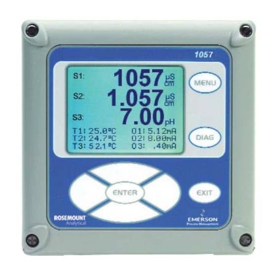
4.3 MAIN DISPLAY 4.4 MENU SYSTEM 4.1 USER INTERFACE The Model 1057 has a large display which shows three live measurement readouts in large digits and up to six additional process variables or diagnostic parameters concurrently. The display is back-lit and the format can be customized to meet user requirements. -
Page 24: Main Display
4. move the cursor to the right or left 5. select measurement units during operations 4.3 MAIN DISPLAY The Model 1057 displays one, two or three primary meas- urement values, up to six secondary measurement values, a fault and warning banner, alarm relay flags. -
Page 25: Menu System
4.4 MENU SYSTEM Model 1057 uses a scroll and select menu system. Pressing the MENU key at any time opens the top-level menu including Calibrate, Hold, Program and Display functions. -
Page 26: Formatting The Main Display
MODEL 1057 SECTION 4.0 DISPLAY AND OPERATION FIGURE 4-1 Formatting the Main Display... -
Page 27: Programming The Analyzer - Basics
MODEL 1057 SECTION 5.0 PROGRAMMING THE ANALYZER - BASICS SECTION 5.0. PROGRAMMING THE ANALYZER - BASICS 5.1 GENERAL 5.2 CHANGING START-UP SETTINGS 5.3 PROGRAMMING TEMPERATURE 5.4 CONFIGURING AND RANGING 4-20MA OUTPUTS 5.5 SETTING SECURITY CODES 5.6 SECURITY ACCESS 5.7 USING HOLD 5.8 RESETTING FACTORY DEFAULTS –... -
Page 28: Choosing Temperature Units And Automatic/Manual Temperature Compensation
S3:123.4µS/cm 123.4ºC Temperature correction can also be turned off. If tem- Temperature perature correction is off, the Model 1057 uses the tem- Units: °C perature entered by the user in all temperature correc- S1 Temp Comp: Auto tion calculations. -
Page 29: Configuring And Ranging The Current Outputs
MODEL 1057 SECTION 5.0 PROGRAMMING THE ANALYZER - BASICS 5.4.3 Procedure: Configure Outputs. S1: 1.234µS/cm 123.4ºC S2: 12.34pH 123.4ºC Under the Program/Outputs menu, the adjacent screen S3:123.4µS/cm 123.4ºC will appear to allow configuration of the outputs. Follow OutputM Configure the menu screens in Fig. 5-2 to configure the outputs. -
Page 30: Setting A Security Code
Model 1057 has two levels of security code to control communication to operators or technicians as access and use of the instrument to different types of needed. -
Page 31: Security Access
MODEL 1057 SECTION 5.0 PROGRAMMING THE ANALYZER - BASICS 5.6 SECURITY ACCESS 5.7 USING HOLD 5.6.1 How the Security Code Works 5.7.1 Purpose When entering the correct access code for the The analyzer output is always proportional to measured Calibration/Hold security level, the Calibration and value. -
Page 32: Resetting Factory Default Settings
5.8.1 Purpose. This section describes how to restore factory calibration and default values. The process also clears all fault messages and returns the display to the first Quick Start screen. The Model 1057 offers three options for resetting factory defaults. -
Page 33: Programming Alarm Relays
5.9 Programming Alarm Relays 5.9.1 Purpose. The Model 1057 24VDC (-02 order code) and the AC switching power supply (-03 order code) provide four alarm relays for process measurement or temperature. Each alarm can be configured as a fault alarm instead of a process alarm. - Page 34 MODEL 1057 SECTION 5.0 PROGRAMMING THE ANALYZER - BASICS 5.9.2 Procedure – Enter Setpoints S1: 1.234µS/cm 1.234ºC Under the Program/Alarms menu, this screen will S2: 12.34pH 1.234ºC S3: 12.34µS/cm 1.234ºC appear to allow configuration of the alarm relays. Alarm1 S2 Setpoint Enter the desired value for the process measurement +100.0uS/cm...
- Page 35 MODEL 1057 SECTION 5.0 PROGRAMMING THE ANALYZER - BASICS 5.9.8 Procedure – Interval time S1: 1.234µS/cm 1.234ºC Under the Alarms Settings menu, this screen will S2: 12.34pH 1.234ºC S3: 12.34µS/cm 1.234ºC appear to set the interval time. Enter the fixed time in Alarm1 Interval Time hours between relay activations.
- Page 36 MODEL 1057 SECTION 5.0 PROGRAMMING THE ANALYZER - BASICS This page left blank intentionally...
-
Page 37: Programming - Measurements
6.4 CONTACTING CONDUCTIVITY 6.1 PROGRAMMING MEASUREMENTS – INTRODUCTION The Model 1057 automatically recognizes each installed measurement board upon first power-up and each time the analyzer is powered. Completion of Quick Start screens upon first power up enable measurements, but addi- tional steps may be required to program the analyzer for the desired measurement application. -
Page 38: Ph Measurement Programming
The following sub-sections provide you with the initial display screen that appears for each configuration function. Use the flow diagram for pH programming at the end of Sec. 6 and the Model 1057 live screen prompts for each function to complete configuration and programming. -
Page 39: Orp Measurement Programming
Refer to the pH/ORP Programming flow diagram to complete this function. High 6.3 ORP MEASUREMENT PROGRAMMING 6.3.1 Description The section describes how to configure the Model 1057 analyzer for ORP measurements. The following programming and configuration functions are covered: TABLE 6-2. ORP Measurement Programming Measure Sec. - Page 40 The following sub-sections provide you with the initial display screen that appears for each configuration function. Use the flow diagram for ORP programming at the end of Sec. 6 and the Model 1057 live screen prompts for each function to complete configuration and programming.
-
Page 41: Contacting Conductivity Measurement Programming
The following sub-sections provide you with the initial display screen that appears for each configuration function. Use the flow diagram for contacting conductivity programming at the end of Sec. 6 and the Model 1057 live screen prompts for each function to complete configuration and programming. - Page 42 MODEL 1057 SECTION 6.0 PROGRAMMING THE MEASUREMENTS 6.4.3 Measure S1: 1.234µS/cm 1.234ºC S2: 12.34pH 1.234ºC The display screen for selecting the measurement is S3: 12.34µS/cm 1.234ºC shown. The default value is displayed in bold type. SN Measurement Refer to the contacting conductivity Programming flow Conductivity diagram to complete this function.
- Page 43 MODEL 1057 SECTION 6.0 PROGRAMMING THE MEASUREMENTS 6.4.9 Slope S1: 1.234µS/cm 1.234ºC The display screen for Entering the conductivity/temp S2: 12.34pH 1.234ºC Slope is shown. The default value is displayed in bold S3: 12.34µS/cm 1.234ºC SN Slope type. Refer to the contacting conductivity Programming 2.00 %/ºC...
- Page 44 MODEL 1057 SECTION 6.0 PROGRAMMING THE MEASUREMENTS...
- Page 45 MODEL 1057 SECTION 6.0 PROGRAMMING THE MEASUREMENTS...
- Page 46 This page left blank intentionally...
-
Page 47: Calibration
Auto calibration avoids common pitfalls and reduces errors. The analyzer recognizes the buffers and uses temperature-corrected pH values in the calibration. Once the Model 1057 successfully completes the calibration, it calcu- lates and displays the calibration slope and offset. The slope is reported as the slope at 25°C. - Page 48 MODEL 1057 SECTION 7.0 CALIBRATION To calibrate pH: The following screen will appear. To calibrate pH or Press the MENU button Temperature scroll to the desired item and press Select Calibrate. Press ENTER. ENTER. S1: 1.234µS/cm 1.234ºC Select Sensor 1 or Sensor 2 corresponding to S2: 12.34pH...
- Page 49 1.234ºC If the electrode slope is known from other measure- S3: 12.34µS/cm 1.234ºC ments, it can be entered directly in the Model 1057 ana- SN pH Slope@25ºC lyzer. The slope must be entered as the slope at 25°C. 59.16 mV/pH 7.2.5 STANDARDIZATION —...
-
Page 50: Orp Calibration Routine
For process control, it is often important to make the measured ORP agree with the ORP of a standard solution. During calibration, the measured ORP is made equal to the ORP of a standard solution at a single point. THIS SECTION DESCRIBES HOW TO CALIBRATE THE MODEL 1057 WITH AN ORP SENSOR. THE FOL- LOWING CALIBRATION ROUTINE IS COVERED. -
Page 51: Contacting Conductivity Calibration Routines
THIS SECTION DESCRIBES HOW TO CALIBRATE THE MODEL 1057 WITH AN ATTACHED CONTACTING CONDUCTIVITY SENSOR. THE FOLLOWING CALIBRATION ROUTINES ARE COVERED. TABLE 7-3... - Page 52 MODEL 1057 SECTION 7.0 CALIBRATION 7.4.2 ENTERING THE CELL CONSTANT New conductivity sensors rarely need calibration. The cell constant printed on the label is sufficiently accurate for most applications. The cell constant should be entered: S1: 1.234µS/cm 1.234ºC • When the unit is installed for the first time S2: 12.34pH...
- Page 53 7.4.5 CALIBRATING THE SENSOR TO A LABORATORY INSTRUMENT (METER CAL) This procedure is used to check and correct the conductivity reading of the Model 1057 using a laboratory conductivity instrument. This is done by submerging the conductivity probe in a bath and measuring the conduc- tivity of a grab sample of the same bath water with a separate laboratory instrument.
-
Page 54: Calibrating Temperature
Most liquid analytical measurements require temperature compensation (except ORP). The Model 1057 performs temperature compensation automatically by applying internal temperature correction algorithms. Temperature cor- rection can also be turned off. If temperature correction is off, the Model 1057 uses the manual temperature entered by the user in all temperature correction calculations. - Page 55 MODEL 1057 SECTION 7.0 CALIBRATION...
- Page 56 MODEL 1057 SECTION 7.0 CALIBRATION...
- Page 57 MODEL 1057 SECTION 7.0 CALIBRATION...
- Page 58 MODEL 1057 SECTION 7.0 CALIBRATION...
-
Page 59: Return Of Material
MODEL 1057 SECTION 8.0 RETURN OF MATERIAL SECTION 8.0 RETURN OF MATERIAL 8.1 GENERAL To expedite the repair and return of instruments, proper communication between the customer and the factory is important. Before returning a product for repair, call 1-949-757-8500 for a Return Materials Authorization (RMA) number. -
Page 60: Warranty
FOR PARTICULAR PURPOSE, OR ANY OTHER MATTER WITH RESPECT TO ANY OF THE GOODS OR SERVICES. RETURN OF MATERIAL Material returned for repair, whether in or out of warranty, should be shipped prepaid to: Emerson Process Management Liquid Division 2400 Barranca Parkway... -
Page 61: Ordering Information
8 local languages, removable connectors for easy wiring, 4 solid plugs for closure of openings, and panel mount hardware. All configurations of Model 1057 can be ordered to meet UL approval requirements. Model 1057 is Class I, Div 2 approved for hazardous area installations by CSA. - Page 62 The right people, the right answers, right now. ON-LINE ORDERING NOW AVAILABLE ON OUR WEB SITE http://www.raihome.com Credit Cards for U.S. Purchases Only. Emerson Process Management Rosemount Analytical Inc. 2400 Barranca Parkway Irvine, CA 92606 USA Tel: (949) 757-8500 Fax: (949) 474-7250 http://www.raihome.com...
Need help?
Do you have a question about the 1057 and is the answer not in the manual?
Questions and answers