
Related Manuals for Emerson Daniel Series


Summary of Contents for Emerson Daniel Series
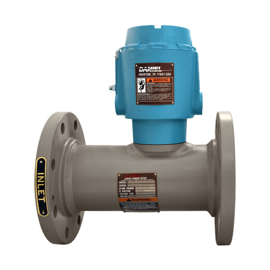
- Page 1 User manual P/N 3-9008-513, Rev AG September 2020 ™ Daniel Series 1200 Liquid Turbine Meter NPS 1 through 4...
- Page 2 Emerson employees. Emerson will not accept your returned equipment if you fail to follow Emerson procedures. Return procedures and forms are available on our web support site at www.emerson.com, or by phoning the Emerson Customer Service department.
-
Page 3: Table Of Contents
User manual Contents P/N 3-9008-513 September 2020 Contents Part I Plan Chapter 1 Introduction......................7 1.1 Purpose of this manual........................ 7 1.2 Hazard messages......................... 7 1.3 Personnel qualifications....................... 7 1.4 Warranty restrictions........................9 1.5 Assistance............................9 1.6 Description of the Series 1200 Liquid Turbine Meter (LTM)............10 1.7 Agency certifications for the Series 1200 LTM................ - Page 4 10.2 Verify the return to operational condition................91 Chapter 11 Spare parts.......................93 11.1 Recommended spare parts...................... 93 Chapter 12 Decommission the turbine meter................95 12.1 Shut down the turbine meter....................95 12.2 Turbine meter disassembly/assembly..................95 12.3 Shipment of the meter......................96 Daniel Series 1200 Liquid Turbine Meter...
-
Page 5: Part I Plan
User manual Plan P/N 3-9008-513 September 2020 Part I Plan User manual... - Page 6 Plan User manual September 2020 P/N 3-9008-513 Daniel Series 1200 Liquid Turbine Meter...
-
Page 7: Chapter 1 Introduction
September 2020 Introduction Purpose of this manual Emerson Daniel designed this manual to guide owners and personnel in the installation, operation and maintenance of the Daniel Series 1200 Liquid Turbine Meter Manual, 3-9008-513. It is imperative that product owners and operation personnel read and follow the information contained in this manual to ensure that the turbine meter is installed correctly and is operating according to the design, certifications and safety considerations. - Page 8 To ensure safe and proper performance, only informed and trained personnel should install, operate, repair and maintain this product. For further questions about training requirements, contact your local Emerson representative. Operations risk assessment must be used and followed in conjunction with this document when performing all online retrieval operations.
-
Page 9: Warranty Restrictions
Emerson assumes no responsibility for incidents, or consequences of incidents, occurring as a result of the use of this product by others than Emerson or its designated personnel, and have no liability whatsoever for any such work. -
Page 10: Description Of The Series 1200 Liquid Turbine Meter (Ltm)
1.6.1 General features of the turbine meter The Daniel Series 1200 Liquid Turbine Meter (LTM) is a volumetric flow metering and transmitting device used extensively in the petroleum industry for the accurate measurement of liquid hydrocarbons. The turbine meter's simple configuration ensures higher flow rates, extended flow range and sustained performance capability. - Page 11 • All Daniel Series 1200 Liquid Turbine Meters have, as standard, the LME which is fitted with two pickoffs and a dual channel preamplifier. •...
- Page 12 Introduction User manual September 2020 P/N 3-9008-513 LME assembly - Standard enclosure Figure 1-1: Part identification for a standard enclosure Daniel Series 1200 Liquid Turbine Meter...
- Page 13 User manual Introduction P/N 3-9008-513 September 2020 Table 1-1: Part description for a standard enclosure Item Description Part number Quantity number required End cap solid 1-360-00-025 Electronics enclosure 899-10-110-60 Plug pipe hex socket 154717-019 Grounding clamp B18934-004 Mounting bracket 899-10-230-50 Socket head screw 899-10-230-52 Warning tag-Hazard...
- Page 14 Introduction User manual September 2020 P/N 3-9008-513 LME assembly - Internal Totalizer Figure 1-2: Part identification for the LME with Internal Totalizer Daniel Series 1200 Liquid Turbine Meter...
- Page 15 User manual Introduction P/N 3-9008-513 September 2020 Table 1-2: Part description for the LME with Internal Totalizer Item Description Part number Quantity number required Cover (SS/ALUM) 899-10-230-60/70 Electronics enclosure (SS/ALUM) 899-10-110-60/70 Plug pipe hex socket 154717-019 Grounding cap B18934-004 Mounting bracket 899-10-230-50 Socket head screw 899-10-230-52...
- Page 16 User manual September 2020 P/N 3-9008-513 Meter housing internal components - NPS 1 The information below identifies and describes the NPS 1 meter housing components. Figure 1-3: Part identification for an NPS 1 LTM Daniel Series 1200 Liquid Turbine Meter...
- Page 17 User manual Introduction P/N 3-9008-513 September 2020 Table 1-3: Part description for an NPS 1 LTM Item Description Part number Quantity number required Rotor 798-10-019-00 O-Ring 1500093-022 Clip 1-504-05-520 Sleeve 797-10-500-60 Hanger blade 798-10-080-00 Hanger hub 798-10-008-00 Shaft 798-10-018-00 Bearing 1505024 Spacer 798-10-073-00...
- Page 18 Meter housing internal components - NPS 1.5 through 2 The information below identifies and describes the NPS 1.5 through 2 meter housing components. Figure 1-4: Part identification for an NPS 1.5 through 2 LTM Daniel Series 1200 Liquid Turbine Meter...
- Page 19 User manual Introduction P/N 3-9008-513 September 2020 Table 1-4: Part description for an NPS 1.5 LTM Item Description Part number for Quantity number material 304 SS required 151687 Washer 151891 Flow conditioning plate 798-14-301-01 Hanger blade 798-14-070-00 Hanger hub 798-14-308-00 Bearing 155195 Spacer...
- Page 20 Introduction User manual September 2020 P/N 3-9008-513 Note For alternative materials and NACE, contact Daniel Sales and Service. Daniel Series 1200 Liquid Turbine Meter...
- Page 21 User manual Introduction P/N 3-9008-513 September 2020 Meter housing internal components - NPS 3 through 4 - Stainless steel bearing internals The information below identifies and describes the NPS 3 through 4 stainless steel meter housing components. Figure 1-5: Part identification for an NPS 3 through 4 LTM - Stainless steel bearing internals User manual...
- Page 22 Table 1-7: Part description for an NPS 4 LTM - Stainless steel bearing internals Item Description Part number Quantity number required 151685 Flow Conditioning 798-22-301-01 Plate - Thermoplastic Flow Conditioning 788-22-301-02 Plate - Aluminum Rotor assembly 798-22-319-00 Daniel Series 1200 Liquid Turbine Meter...
- Page 23 User manual Introduction P/N 3-9008-513 September 2020 Table 1-7: Part description for an NPS 4 LTM - Stainless steel bearing internals (continued) Item Description Part number Quantity number required O-ring 1500093-022 Washer 151857-419 Diffuser 798-22-008-00 Support fin 798-22-070-00 Pickoff 899-00-201-00 Screw (hex head) 150739-419 Retaining ring...
- Page 24 Tungsten carbide bearing internals The information below identifies and describes the NPS 3 through 4 tungsten carbide meter housing components. Figure 1-6: Part identification for an NPS 3 through 4 LTM -Tungsten carbide bearing internals Daniel Series 1200 Liquid Turbine Meter...
- Page 25 User manual Introduction P/N 3-9008-513 September 2020 Table 1-8: Part description for an NPS 3 LTM -Tungsten carbide bearing internals Item Description Part number Quantity number required 151687 Flow Conditioning 798-20-301-01 Plate - Thermoplastic Flow Conditioning 798-20-301-02 Plate - Aluminum Rotor assembly 798-20-319-01 O-ring...
- Page 26 Outlet diffuser cap 798-22-013-00 Belleville washer 1500422 151650 Cotter pin 153930 Meter housing Class 150 798-22-312-61M 1 Class 300 798-22-332-61M 1 Anti-rotation bracket clamp 899-10-230-66 Note For alternative materials and NACE, contact Daniel Sales and Service. Daniel Series 1200 Liquid Turbine Meter...
-
Page 27: Agency Certifications For The Series 1200 Ltm
User manual Introduction P/N 3-9008-513 September 2020 Agency certifications for the Series 1200 LTM The following are product agency certifications applicable to the Daniel Series 1200 LTM. Table 1-10: Agency certifications for the Series 1200 LTM Certification type Description Certificate Electrical UL and CUL: Class I, Div. - Page 28 Introduction User manual September 2020 P/N 3-9008-513 Daniel Series 1200 Liquid Turbine Meter...
-
Page 29: Operating Conditions And Specifications
-40 ºC to 60 ºC (-40 ºF to 140 ºF) (Stainless steel flanges) Fluid static pressure The maximum working pressure for the Daniel Series 1200 Liquid Turbine Meter is based on the temperature/ pressure rating of the ANSI B16.5 flanges. For maximum working pressures at intermediate temperatures refer to ANSI B16.5. - Page 30 Install the turbine meter in a well ventilated area, not less than and combustion sources one meter (approximately 3 feet) from source of ignition or source of heat which might damage the unit. Elevation No limit. Humidity No limit. Daniel Series 1200 Liquid Turbine Meter...
- Page 31 User manual Operating conditions and specifications P/N 3-9008-513 September 2020 Table 2-2: Environmental conditions (continued) Parameter type Description Proximity to open flame Provide fire prevention measures and equipment per local regulations. Proximity to vehicular traffic The design of the turbine meter has not been assessed for the effects of traffic loads.
- Page 32 The metering system should have a flow rate control valve located at a convenient distance downstream of all measurement equipment. The function of the control valve is to limit and maintain system pressure on the meter. This avoids cavitation. Daniel Series 1200 Liquid Turbine Meter...
-
Page 33: Specifications For The Ltm
User manual Operating conditions and specifications P/N 3-9008-513 September 2020 Valves should be capable of rapid, smooth opening and closing with positive shut-off. • When used for intermittent flow, valves should be fast-acting and shock-free. • Bypass lines should be equipped with blind or positive shutoff devices. •... - Page 34 The LME housing should be at earth ground. Table 2-4: 2818 Dual channel preamplifier configuration Plug component designator Terminal connections Description TB1 - Customer connection +10 to 30 Vdc Common Common Channel A output Channel B output Daniel Series 1200 Liquid Turbine Meter...
- Page 35 It is important that the correct service manual be referenced before attempting to use accessories or instrumentation with the Series 1200 LTM. Contact the factory or nearest Emerson service office if service manuals were not received at the time of purchase or delivery.
- Page 36 Important A spool piece installed in place of the turbine meter is recommended for this procedure. NOTICE Comply with local government regulations and company requirements. Daniel Series 1200 Liquid Turbine Meter...
- Page 37 User manual Operating conditions and specifications P/N 3-9008-513 September 2020 Minimum clearances for installation, operation and maintenance Below is the approximate shipping dimensions and weight for the Series 1200 LTM NPS 1-4. For certified dimension prints, please consult the factory. Figure 2-3: Dimensions for the Series 1200 LTM NPS 1-4 Table 2-5: Flow meter and flow straightening section dimensions for the Series 1200 LTM NPS 1-4...
- Page 38 Table 2-6: Flow meter and flow straightening section dimensions for the Series 1200 LTM NPS 1-4 (continued) Size Inches Inches Inches 1016 1829 Table 2-7: Weight table for the stainless steel LME Size ANSI class 150 ANSI class 300 Daniel Series 1200 Liquid Turbine Meter...
-
Page 39: Turbine Meter Handling
User manual Turbine meter handling P/N 3-9008-513 September 2020 Turbine meter handling Receive the turbine meter WARNING EQUIPMENT HANDLING AND OPERATING HAZARD Wear personal protective equipment appropriate to the situation when working with the turbine meter. Adhere to all safety standards and best practices for operating the equipment. - Page 40 Do not remove nameplates or labels. Doing so will void the turbine meter warranty. Stacking When stacking equipment, follow all safety standards, taking into account the type of box used, the maximum height of the equipment, the maximum number of boxes stacked, etc. Daniel Series 1200 Liquid Turbine Meter...
-
Page 41: Prepare The Turbine Meter For Use
User manual Prepare the turbine meter for use P/N 3-9008-513 September 2020 Prepare the turbine meter for use Lifting conditions WARNING CRUSHING HAZARD During turbine meter installation or removal, always place the unit on a stable platform or surface that supports its assembled weight. Failure to comply could allow the turbine meter to roll, resulting in death, serious injury or equipment damage. -
Page 42: Lifting Requirements For Personnel
Minimum clearances for installation, operation and maintenance for the assemble weight. The following instructions provide general guidelines using lifting slings only on the Daniel turbine meter. Use appropriately rated lifting slings when lifting the turbine meter. Daniel Series 1200 Liquid Turbine Meter... - Page 43 Prepare the turbine meter for use P/N 3-9008-513 September 2020 Safety precautions using appropriately rated lifting slings When lifting a liquid turbine meter by itself, Emerson recommends using lifting slings appropriately positioned at designated areas of the turbine meter. WARNING LIFTING HAZARD...
- Page 44 Doing this may cause injury and/or damage the equipment. • Never apply shock loads to the turbine meter. Always lift the turbine meter gradually. If shock loading occurs, inspect the slings per manufacturer's recommendations prior to further use. Daniel Series 1200 Liquid Turbine Meter...
-
Page 45: Configuration Of The Turbine Meter
Prepare the turbine meter for use P/N 3-9008-513 September 2020 Configuration of the turbine meter The Emerson factory configures the turbine meter internal components. Inspect the internal components before installation. 4.3.1 Orientation and position of the turbine meter Flow direction Turbine meters can be used for uni-directional flows. - Page 46 Dual channel Inputs Supply voltage: 10-30 VDC preamplifier Sensor type: Reluctance Signal: Sine wave Preamplifier sensitivity: 40 mV peak to peak minimum Temperature range: -40 ºC to 85 ºC (-40 ºF to 185 ºF) Daniel Series 1200 Liquid Turbine Meter...
- Page 47 User manual Prepare the turbine meter for use P/N 3-9008-513 September 2020 Table 4-3: Preamplifier power requirements (continued) Power requirement Description type Outputs Powered pulse output: • Type: Square wave • Frequency range: 0 to 5 kHz • Amplitude: 0 to 5 V •...
- Page 48 Security seals protect the integrity of the turbine meter metrology and prevent tampering with the preamplifier and pickoffs. The section below details how to properly seal the Daniel 1200 LTM after commissioning. The security seal wires are commercially available. Daniel Series 1200 Liquid Turbine Meter...
- Page 49 User manual Prepare the turbine meter for use P/N 3-9008-513 September 2020 CAUTION CUTTING HAZARD Sharp edges may be present on the band shrouds. Wear appropriate personal protective equipment when working on the turbine meter. Failure to comply may cause serious injury. Figure 4-6: Security seal wire Follow the steps below to seal the electronics enclosure.
- Page 50 Prepare the turbine meter for use User manual September 2020 P/N 3-9008-513 Daniel Series 1200 Liquid Turbine Meter...
-
Page 51: Part Ii Install
User manual Install P/N 3-9008-513 September 2020 Part II Install User manual... - Page 52 Install User manual September 2020 P/N 3-9008-513 Daniel Series 1200 Liquid Turbine Meter...
-
Page 53: Chapter 5 Installation Prerequisites
User manual Installation prerequisites P/N 3-9008-513 September 2020 Installation prerequisites Pre-start checks Procedure 1. Inspect all electrical connections to ensure compliance to electrical codes and safety regulations. 2. Inspect all bolts used to secure the turbine meter in line to ensure that correct mounting procedures have been followed and that flange connections are leak- free. - Page 54 Installation prerequisites User manual September 2020 P/N 3-9008-513 Daniel Series 1200 Liquid Turbine Meter...
-
Page 55: Chapter 6 Installation Procedure
User manual Installation procedure P/N 3-9008-513 September 2020 Installation procedure Cathodic protection Table 6-1: Standards for cathodic protection Material Daniel standard cathodic protection Carbon steel Zinc Phosphate Consult the factory for other protection. Mechanical components assembly Install the meter housing (e.g., flanges) onto the pipeline. The meter housing internal components are assembled by the factory. -
Page 56: Assemble The Electronic Components
Failure to comply may result in death or serious injury. Procedure 1. Remove the security seal wire. 2. Remove the security latch using the 3 mm Allen key. Daniel Series 1200 Liquid Turbine Meter... - Page 57 5. Install the electronics according to Wiring and cable connections. Consult with Emerson if the preamplifier acquired is other than a dual channel preamplifier. WARNING SHOCK AND EXPLOSION HAZARD Verify that the LME and/or RME is grounded.
- Page 58 Installation procedure User manual September 2020 P/N 3-9008-513 Daniel Series 1200 Liquid Turbine Meter...
-
Page 59: Chapter 7 Testing
User manual Testing P/N 3-9008-513 September 2020 Testing Test the turbine meter 7.1.1 Commission the turbine meter After installation, commission the turbine meter to ensure that the equipment is working properly. Procedure 1. Inspect all electrical connections to ensure compliance with electrical codes and safety regulations. - Page 60 Testing User manual September 2020 P/N 3-9008-513 Daniel Series 1200 Liquid Turbine Meter...
- Page 61 User manual Operate P/N 3-9008-513 September 2020 Part III Operate User manual...
- Page 62 Operate User manual September 2020 P/N 3-9008-513 Daniel Series 1200 Liquid Turbine Meter...
-
Page 63: Chapter 8 Operation Parameters
Operation parameters Operation overview The Daniel Series 1200 LTM is a volumetric flow measuring and transmitting device that produces an output signal proportional to the rate-of-flow of the liquid being measured. The primary output is a single or dual high resolution signal that is amplified and shaped by an integral preamplifier mounted within an explosion proof housing. - Page 64 Always use a flushing medium that is compatible with the metallurgy of the meter, internal components. Using water as a flushing medium may result in damage to the internal components of the turbine meter. Daniel Series 1200 Liquid Turbine Meter...
-
Page 65: Part Iv Maintain
User manual Maintain P/N 3-9008-513 September 2020 Part IV Maintain User manual... - Page 66 Maintain User manual September 2020 P/N 3-9008-513 Daniel Series 1200 Liquid Turbine Meter...
-
Page 67: Chapter 9 Planned Maintenance
User manual Planned maintenance P/N 3-9008-513 September 2020 Planned maintenance Maintenance considerations Read and understand all instructions and operating procedures before performing maintenance procedure, internal component inspections or field requirement changes. To ensure safe and accurate performance, only informed and trained personnel should install, operate, repair and maintain this product. -
Page 68: Prepare For Mechanical Disassembly
6. Disconnect conduit connections to the turbine meter. 7. Remove turbine meter from line. Refer to Lifting equipment Lifting conditions, Lifting requirements for personnel, and Safety precautions using appropriately rated lifting slings for instructions on lifting the turbine meter. Daniel Series 1200 Liquid Turbine Meter... - Page 69 User manual Planned maintenance P/N 3-9008-513 September 2020 9.3.1 Disassemble internal meter housing components - NPS Procedure 1. Remove the C-clip at the inlet flange using pliers. Figure 9-1: C-clip removal 2. Remove the sleeve. You may need to GENTLY tap the internals from the downstream end using a soft punch to start the process.
- Page 70 Figure 9-4: Internals of the meter 9.3.2 Disassemble internal meter housing components - NPS 1.5 through 2 Procedure 1. Remove the nut, washer and flow conditioning plate by pulling the parts from the center bolt. Daniel Series 1200 Liquid Turbine Meter...
- Page 71 User manual Planned maintenance P/N 3-9008-513 September 2020 Figure 9-5: Nut, washer and flow conditioning plate removal 2. Lightly tap the center bolt on the end with a soft-faced mallet to loosen the compression on the support fins. Align the shaft flush with the support fins and lift the fins slightly to remove them from the groove inside the flow tube.
- Page 72 The ball races are a loose fit in recesses on the rotor hub and may fall out. Be careful not to lose any small parts. Figure 9-8: Downstream stator and rotor removal 6. Disassemble all the internals. Figure 9-9: Internals disassembly Daniel Series 1200 Liquid Turbine Meter...
- Page 73 User manual Planned maintenance P/N 3-9008-513 September 2020 9.3.3 Disassemble internal meter housing components - NPS 3 through 4 The internal components of the Series 1200 Turbine Meter are held in place by self- centering support fins, pressed against the flow conditioning plate. Procedure 1.
- Page 74 There is an etched “U” on the upstream side of the rotor. Important Handle the rotor with care. Improper handling of the rotor assembly may cause distortion to the rotor blades thereby affecting meter performance. Daniel Series 1200 Liquid Turbine Meter...
- Page 75 User manual Planned maintenance P/N 3-9008-513 September 2020 Figure 9-13: Rotor removal 3. Remove the internal retaining ring holding the bearing assembly in the diffuser. Figure 9-14: Internal retaining ring removal 4. Remove the bearing assembly from the diffuser. Disassembly is complete. Figure 9-15: Bearing assembly removal 5.
- Page 76 Figure 9-17: Cotter pin removal 2. Remove the castle nut from the shaft. Figure 9-18: Castle nut removal 3. Remove the outlet diffuser cap and Belleville washers. Daniel Series 1200 Liquid Turbine Meter...
- Page 77 User manual Planned maintenance P/N 3-9008-513 September 2020 Figure 9-19: Diffuser cap and Belleville washers removal 4. Remove the downstream thrust washer from the shaft. Note that the slot faces the rotor. Figure 9-20: Downstream thrust washer 5. Gently slide the rotor from the bearing shaft. Note the orientation of the rotor. Important Handle the rotor with care.
-
Page 78: Mechanical Assembly
Handle the rotor with care. Improper handling of the rotor assembly may cause distortion to the rotor blades thereby affecting meter performance. Figure 9-24: Internals assembly 2. Install the sleeve. Daniel Series 1200 Liquid Turbine Meter... - Page 79 User manual Planned maintenance P/N 3-9008-513 September 2020 Figure 9-25: Sleeve installation 3. Install the C-clip at the inlet flange using pliers. Figure 9-26: C-clip installation 9.4.2 Assemble internal meter housing components - NPS 1.5 through 2 Procedure 1. Fully assemble the internals. The rotor assembly includes the rotor, two stainless steel ball bearing assemblies and a spacer between the ball races.
- Page 80 2. Install the support fins and nut from the downstream (rotor) end into the internal bullet. Figure 9-28: Support fins and nut installation 3. Gently install the internals into the flow tube. Figure 9-29: Internals installation Daniel Series 1200 Liquid Turbine Meter...
- Page 81 User manual Planned maintenance P/N 3-9008-513 September 2020 4. Lightly tap the center bolt from the downstream rotor end with a soft-faced mallet to tighten the compression on the support fins. 5. Install the nut, washer and flow conditioning plate. Figure 9-30: Nut, washer and flow conditioning plate installation 9.4.3 Assemble internal meter housing components - NPS 3...
- Page 82 Handle the rotor with care. Improper handling of the rotor assembly may cause distortion to the rotor blades, affecting meter performance. Figure 9-34: Rotor installation 5. Install the retaining ring and support fins to the end of the bearing supporting the rotor. Daniel Series 1200 Liquid Turbine Meter...
- Page 83 User manual Planned maintenance P/N 3-9008-513 September 2020 Figure 9-35: Retaining ring installation 6. Gently install the internals into the flow tube. Figure 9-36: Internals installation 7. Lightly tap the center bolt from the downstream rotor end with a soft-faced mallet to tighten the compression on the support fins.
- Page 84 Procedure 1. Install the upstream thrust washer. Note that the slot faces the rotor. Figure 9-38: Upstream thrust washer installation 2. Install the shaft sleeve from the bearing shaft. Figure 9-39: Shaft sleeve installation Daniel Series 1200 Liquid Turbine Meter...
- Page 85 User manual Planned maintenance P/N 3-9008-513 September 2020 3. Gently slide the rotor into the bearing shaft. Note the orientation of the rotor. Important Handle the rotor with care. Improper handling of the rotor assembly may cause distortion to the rotor blades thereby affecting meter performance. Figure 9-40: Rotor installation 4.
- Page 86 Do not turn the nut counterclockwise to align the cotter pin hole. The nut must be tight on the shaft. Figure 9-44: Cotter pin and support fins installation 8. Gently install the internals into the flow tube. Daniel Series 1200 Liquid Turbine Meter...
- Page 87 User manual Planned maintenance P/N 3-9008-513 September 2020 Figure 9-45: Internals installation 9. Lightly tap the center bolt from the downstream rotor end with a soft-faced mallet to tighten the compression on the support fins. 10. Install the nut, washer and flow conditioning plate if necessary. Figure 9-46: Nut, washer and flow conditioning plate installation User manual...
-
Page 88: Electronics Enclosure Disassembly
LME housing and Sensor housing is a spigot joint with a minimum axial length of 26.16 mm (1.030 in), radial length of 3.18 mm (0.125 in), and a clearance of 0.07 mm (0.0028 in). Daniel Series 1200 Liquid Turbine Meter... -
Page 89: Replace The Preamplifier
User manual Planned maintenance P/N 3-9008-513 September 2020 9.6.1 Assemble the LME - Standard enclosure Procedure 1. Install the O-ring on the pad. 2. Install the housing on the turbine meter body or remote mounting pad. Use four screws with a torque value of 74.5 Nm (55 lbs-ft) (Capacity to be installed: each at 90º). -
Page 90: Planned Maintenance Tasks
A careful review of turbine meter proving history, such as turbine meter factor control charts, can reveal potential problems with turbine meter measurements. Examples include bearing drag due to wear or an increased internal cross-sectional area due to erosion. Daniel Series 1200 Liquid Turbine Meter... -
Page 91: Chapter 10 Corrective Maintenance
September 2020 Corrective maintenance 10.1 Turbine meter troubleshooting Use the table below to troubleshoot the turbine meter. Contact the nearest Emerson service office for repairs. It is important that servicing be performed by trained and qualified service personnel. Table 10-1: Troubleshooting... - Page 92 3. Evaluate the system setup to ensure that all components are in the correct sequence for accurate product measurement: isolation valve, strainer, flow straightener, turbine meter, downstream section, control valve, etc. 4. Ensure that the supply voltage to the preamplifier is within the 10-30 VDC range. Daniel Series 1200 Liquid Turbine Meter...
-
Page 93: Chapter 11 Spare Parts
User manual Spare parts P/N 3-9008-513 September 2020 Spare parts 11.1 Recommended spare parts The figure below identifies the spare parts for an LME assembly. Figure 11-1: Part identification for a standard enclosure User manual... - Page 94 Refer to Interface parameters for detailed preamplifier information. Refer toLME assembly - Standard enclosure Order spare parts Contact Emerson Flow customer service and provide the following information when ordering spare parts: • Turbine meter serial number • Part number •...
-
Page 95: Decommission The Turbine Meter
User manual Decommission the turbine meter P/N 3-9008-513 September 2020 Decommission the turbine meter 12.1 Shut down the turbine meter Follow the steps below to shut down and disassemble the turbine meter for storage or shipment. WARNING PRESSURE HAZARD The turbine meter is subject to pressurized fluids. Depressurize the turbine meter before disassembly. -
Page 96: Shipment Of The Meter
Decommission the turbine meter User manual September 2020 P/N 3-9008-513 12.3 Shipment of the meter Refer to the Emerson Flow customer service information in the preface of this document. Daniel Series 1200 Liquid Turbine Meter... - Page 97 User manual P/N 3-9008-513 September 2020 User manual...
- Page 98 Daniel ("Daniel") is an Emerson Automation Solutions brand. The Daniel name and logo are trademarks of Emerson. The Emerson logo is a trademark and service mark of Emerson Electric Co. All other trademarks are the property of their respective companies.
Need help?
Do you have a question about the Daniel Series and is the answer not in the manual?
Questions and answers