
Subscribe to Our Youtube Channel
Related Manuals for Nvidia Spectrum-2 SN3000 1U


Summary of Contents for Nvidia Spectrum-2 SN3000 1U
- Page 1 NVIDIA Spectrum-2 SN3000 1U and 2U Switch Systems Hardware User Manual NVIDIA Spectrum-2 SN3000 1U and 2U Switch Systems Hardware User Manual, SN3420, SN3700, SN3700C, SN3800 Exported on Nov/06/2023 12:51 PM...
-
Page 2: Table Of Contents
Power Cable and Cable Retainer ............34 Port Cables..................36 Initial Power On ..................39 System Bring-Up..................40 Configuring Network Attributes Using NVIDIA Onyx (MLNX-OS) ......40 Configuring Network Attributes Using Cumulus Linux ........43 FRU Replacements ................. 43 Power Supplies ................. 44 Fans .................... - Page 3 Unit Identification LED................ 62 Port LEDs ..................62 Inventory Information ................65 Software Management ...............67 Software Upgrade.................. 67 NVIDIA Onyx (MLNX-OS) Software Upgrade..........67 Switch Firmware Update..............67 Cumulus Linux Software Upgrade ............67 Troubleshooting ................68 Specifications..................70 SN3700/SN3700C Specifications ..............70 SN3750-SX Specifications .................
- Page 4 RJ45 to DB9 Harness Pinout ..............79 Disassembly and Disposal ................. 79 Disassembly Procedure ................ 79 Disposal..................79 Document Revision History ..............81 ...
- Page 5 Relevant for Models: SN3420, SN3700, SN3700C and SN3750-SX. About this Manual This manual describes the installation and basic use of NVIDIA Ethernet switches based on the NVIDIA Spectrum-2 ASIC. Ordering Information See Ordering Information. Intended Audience This manual is intended for IT managers and system administrators.
-
Page 6: Ordering Information
Phase SN3700C 920-9N201-00 MSN3700- NVIDIA Spectrum®-2 based 100GbE 1U Open Ethernet Switch F7-0X0 CS2F with NVIDIA Onyx, 32 QSFP28 ports, 2 Power Supplies (AC), (Mass Standard depth, x86 CPU, P2C airflow, Rail Kit Producti 920-9N201-00 MSN3700- NVIDIA Spectrum®-2 based 100GbE 1U Open Ethernet Switch R7-0X0 ... - Page 7 SN3700 920-9N201-00 MSN3700- NVIDIA Spectrum®-2 based 200GbE 1U Open Ethernet Switch FA-0X0 VS2F with NVIDIA Onyx, 32 QSFP56 ports, 2 Power Supplies (AC), (End of Standard depth, x86 CPU, P2C airflow, Rail Kit Life) 920-9N201-00 MSN3700- NVIDIA Spectrum®-2 based 200GbE 1U Open Ethernet Switch RA-0X0 ...
-
Page 8: Sn3750-Sx Ordering Part Numbers
Legacy Description Model SN3750X 920-9N210-00FA MSN3750- NVIDIA Spectrum-2 based 200GbE 1U X-Haul Ethernet Switch with -0C0 VS2FSO ONIE, 32 QSFP56 ports, 2 Power Supplies (AC), x86 CPU, Secured- boot, standard depth, P2C airflow, SyncE and PPS, Rail Kit 920-9N210-00FA MSN3750- NVIDIA Spectrum-2 based 200GbE 1U X-Haul Ethernet Switch with -0N5 ... - Page 9 NVIDIA SKU Legacy Description Model 920-9N210-00FA MSN3750- NVIDIA Spectrum-2 based 200GbE 1U X-Haul Ethernet Switch with -0C1 VS2FSC Cumulus Linux, 32 QSFP56 ports, 2 Power Supplies (AC), x86 CPU, Secured-boot, standard depth, P2C airflow, SyncE and PPS, Rail Kit 920-9N210-00FA...
-
Page 10: Introduction
3.58Bpps. The SN3420 enables the seamless use of QSFP28 connections for leaf-spine topology and future-proofing the data center. NVIDIA SN3700 200GbE spine/super-spine offers 32 ports of 200GbE in a compact 1U form factor. It enables connectivity to endpoints at different speeds and carries a throughput of 6.4Tb/ s, with a landmark 8.33Bpps processing capacity. -
Page 11: Speed And Switching Capabilities
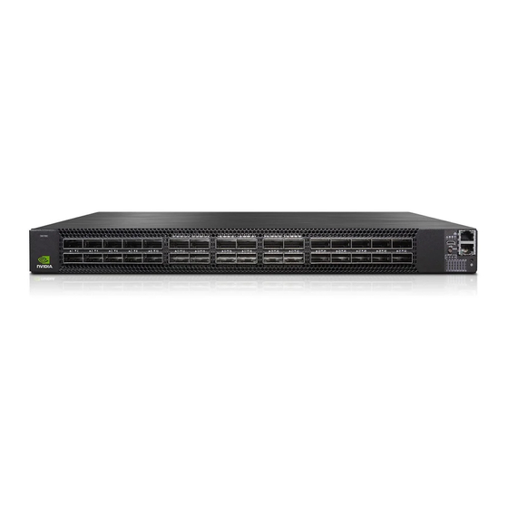
SN3420 Front View SN3420 Rear View SN3700/SN3700C Front View SN3700 Rear View SN3700C Rear View SN3750-SX Front View SN3750-SX Rear View Speed and Switching Capabilities The table below describes maximum throughput and interface speed per system model. System Model Interfaces Supported Rates Max Throughput SN3700C 32 x QSFP28... -
Page 12: Management Interfaces, Psus And Fans
In the main menu, click on Products > Ethernet Switch Systems, and select the desired product family. Certifications The list of certifications (such as EMC, Safety and others) per system for different regions of the world is located on the NVIDIA website at https://www.nvidia.com/en-us/networking/ environmental-and-regulatory-compliance/. -
Page 13: Installation
Unless otherwise specified, NVIDIA products are designed to work in an environmentally controlled data center with low levels of gaseous and dust (particulate) contamination. The operation environment should meet severity level G1 as per ISA 71.04 for gaseous contamination and ISO 14644-1 class 8 for cleanliness level. -
Page 14: Air Flow
The DC disconnect switch must be provided by the customer. Air Flow NVIDIA systems are offered with two air flow patterns: the images are provided for illustration purposes only. The design may slightly vary in different systems •... -
Page 15: Package Contents
1 – Cable retainer for each power supply unit If anything is damaged or missing, contact your sales representative at enterprisesupport@nvidia.com. Mounting Options By default, the systems are sold with fixed rail-kits. Telescopic Rail-kits are available for some systems, and should be purchased separately. For installation instructions, refer to the relevant links in the following table: ... - Page 16 Rack Rail Kit Parts Prerequisites: Before mounting the system to the rack, select the way you wish to place the system. Pay attention to the airflow within the rack cooling, connector and cabling options. While planning how to place the system, consider the two installation options shown in the figures below, and review the following points: •...
- Page 17 Short Racks (430-580 mm) Installation Options Standard Racks (580-800 mm) Installation Options In short racks, the system’s ventilation openings should be framed by the designated windows in the rails, as shown below. Short Racks (430-580 mm) Installation - Side View Front side (ports): Rear side (FRUs): Standard Racks (580-800 mm) Installation - Side View...
- Page 18 To mount the system into the rack: At least two people are required to safely mount the system in the rack. The following steps include illustrations that show front side (ports) installation, yet all instructions apply to all installation options. Attach the left and right rack mount rails (A) to the switch, by gently pushing the switch chassis’...
- Page 19 Install 8 cage nuts (D) in the desired 1U slots of the rack: 4 cage nuts in the non-extractable side and 4 cage nuts in the extractable side. Installing the Cage Nuts While each rack U (unit) consists of three holes, the cage nut should be installed vertically with its ears engaging the top and bottom holes only.
-
Page 20: Sn3700/Sn3700C Telescopic Rail Kit
Sliding the Blades in the Rails When fully inserted, fix the switch by tightening the 8 screws (E) inserted in Step 5 and Step 6 with a torque of 4.5±0.5. Removing the System from the Rack To remove a unit from the rack: Turn off the system and disconnect it from peripherals and from the electrical outlet. - Page 21 • 10x M6 Standard cage nuts¹ ² (E) • 10x M6 Standard pan-head Phillips screws¹ (F) • 2x Phillips100 DEG F.H TYPE-I ST.ST 6-32 X 1/4 screw with around patch (G) • 6x Flat head 100 DEG Phillips 4-40X3/16" ST.ST patch screws (H) ¹...
- Page 22 To separate the rails: Separate rail C from sliders A/B + D. Extend the rail assembly by pulling the extension outwards (D). Rails Separation Before mounting the system to the rack, select the way you wish to place the system. Pay attention to the airflow within the rack cooling, connector and cabling options.
- Page 23 Mounting the Outer Rails into the Rack If cable accommodation is required, disassemble any of the inner rails from the brackets attached to them, by removing and scraping the connecting screws. Disassembling the Inner Rails for Cable Accommodation Route the power cable through either of the inner rails, and reassemble the brackets by screwing the 3 screws (per rail) provided with the rail-kit (H) with a torque of 0.7±0.05Nm. ...
-
Page 24: Removing The System From The Rack
Secure the chassis in the inner rails screwing the 2 flat head Phillips screws (G) in the designated points with a torque of 1.5±0.2 Nm. Securing the Chassis in the Inner Rails Slide the switch into the rack by carefully pushing the inner rails into the outer rails installed on the rack. ... -
Page 25: Sn3750-Sx Tool-Less Rail Kit
Turn off the system and disconnect it from peripherals and from the electrical outlet. Unscrew the two M6 screws securing the front of the inner rails’ ears to the outer rails and to the rack. Pull the unit out until braking is felt. For safety purposes, the locking mechanism will not allow a complete removal of the unit at this stage. - Page 26 Prior to the installation procedure, inspect all rail-kit components and make sure none of them is missing or damaged. If anything is missing or damaged, contact your NVIDIA representative at Networking-support@nvidia.com. The following parts are included in the tool-less rail kit (see figure below): •...
- Page 27 The following steps include illustrations that show front side (ports) installation, yet all instructions apply to all installation options. Attach the left and right system rails (A) to the switch. Attaching the System Rails (A) to the Switch Secure the assembly by gently pushing the system chassis’ pins through the slider key holes, until locking occurs...
- Page 28 Securing the System in the Switch Rails (A) Chassis' Pins in the Rails' Slots Locking them in a Fixed Position Mount both of the rack rails (B) into the rack by angularly inserting the brakes located at the rails edges into the designated slots in the rack unit, as shown in the following figure: ...
- Page 29 Inserting the Rack Rails (B) Align both rack rails (B) to sit horizontally in parallel to the rack assembly. By straightening the rails' angular position, their breaks will be caught and locked in the rack's slots. Aligning the Rack Rails (B) Angular Position The Breaks are Caught and Locked in the Rack's Slots...
- Page 30 Rack Rails Fully Inserted and Locked in the Rack Assembly Pull the rack rails' telescopic extensions all the way to the rack's opposite side, and insert the latches at the rails' free edges to the rack's slots. A click should be heard as the spring latches are fully inserted and locking occurs.
- Page 31 While your installation partner is supporting the system’s weight, perform the following steps: Slide the rails installed on the system into the channels in the rack rails. Push them forward until the locking mechanism is activated on both sides, and a click is heard. Tighten the captive screws on both sides to further secure the system to the rack's posts.
- Page 32 Pulling the System Out Press the spring latches on both sides of the rack, and continue to pull the system out until the rack rails are clear of the system's rails. Pressing the Spring Latches on Both Sides Remove the rails from the system. Release the metal latches and pull out the rails, so the system's pins will be removed out of the oval slots.
- Page 33 Removing the Rails from the System Remove the rails from the rack by pressing the lock button, and pull the rails outside of the rack assembly. Pressing the Lock Button to Remove the Rails from the Rack...
-
Page 34: Cable Installation
Cable Installation Power Cable and Cable Retainer In some switch models, the product's package includes cable retainers. It is highly recommended to use them in order to secure the power cables in place. When installing retainers for the PSUs of the SN3420 switch systems, please adhere to the following instructions: ... - Page 35 Correct Insertion Incorrect Insertion Push the retainer until the shoulders' pins (in blue circles below) are open and aligned with the PSU front panel, as shown in the following table: Fully Mated Retainer Make sure that the retainer is fully locked in place by gently attempting to pull it outwards. Open the plastic loop and route the AC cord through it.
-
Page 36: Port Cables
LED indicator for that port will turn off when the cable is unseated. For a list of Supported Cables and Transceivers, please refer to the SN3000 Systems Datasheet. For full cabling guidelines, please refer to the NVIDIA Cable Management Guidelines and FAQ. For more information about port LEDs, refer to Port LEDs. - Page 37 Splitter (Breakout) Cables and Adapters The 100GbE ports in the SN3420 systems can be split to four (or less) 50GbE ports, using an NVIDIA splitter cable. See "SN3420 Splitting Options” below. The 200GbE ports in the SN3700 systems can be split to two 100GbE ports, or to four (or less) 50GbE ports, using an NVIDIA splitter cable.
- Page 38 SN3420 Splitting Options Ports 49-60 can be split to either two QSFP28 ports or four SFP28 ports. None of the ports are blocked. SN3700 Splitting Options All ports can be split to either 2 QSFP56 ports or 4 SFP56 ports. None of the ports are blocked. SN3700C Splitting Options All ports can be split to either 2 QSFP28 ports or 4 SFP28 ports.
-
Page 39: Initial Power On
If the Fan Status LED is not green, unplug the power connection and check that the fan module is inserted properly and that the mating connector of the fan unit is free of any dirt and/or obstacles. If no obstacles were found and the problem persists, call your NVIDIA representative for assistance. -
Page 40: System Bring-Up
Stabilise’e”. Pour isoler completement le module en cause, Il faut de’brancher toutes les alimentations stabilise’es. System Bring-Up For bring-up of a switch system with NVIDIA Onyx (MLNX-OS) operating system installed, see Configuring Network Attributes Using NVIDIA Onyx (MLNX-OS). For bring-up of a switch system with Cumulus Linux operating system installed, see Configuring... - Page 41 Flow Control None Step 3. Login as admin and use admin as password. On the first login, the NVIDIA Onyx (MLNX-OS) configuration wizard will start. Step 4. To configure network attributes and other initial parameters to the system, follow the configuration wizard as shown in the Configuration Wizard Session table below.
- Page 42 (config) # Step 6. Check the software version embedded in your system, using the command ‘show version’. Compare this version to the latest version that can be retrieved from NVIDIA support site. To upgrade software, please refer to the NVIDIA Onyx (MLNX-OS) User...
-
Page 43: Configuring Network Attributes Using Cumulus Linux
Login as admin (default username is admin, password is admin). Once you get the CLI prompt, you are ready to use the system. For additional information about NVIDIA Onyx (MLNX-OS), refer to the NVIDIA Onyx (MLNX-OS) User Manual located on the NVIDIA Networking Documentation Website. -
Page 44: Power Supplies
Power Supplies NVIDIA systems that are equipped with two replaceable power supply units work in a redundant configuration. Either unit may be extracted without bringing down the system. Make sure that the power supply unit that you are NOT replacing is showing green for the power supply unit LED. -
Page 45: Fans
Do not attempt to insert a power supply unit with a power cord connected to it. Insert the power supply unit by sliding it into the opening, until a slight resistance is felt. Continue pressing the power supply unit until it seats completely. The latch will snap into place, confirming the proper installation. -
Page 46: Sn3510 Fixed Rail Kit
SN3420 Fan Module Latches To insert a fan unit: Make sure the mating connector of the new unit is free of any dirt and/or obstacles. Insert the fan unit by sliding it into the opening until slight resistance is felt. Continue pressing the fan unit until it seats completely. ... - Page 47 Rack Rail Kit Parts Prerequisites: Before mounting the system to the rack, select the way you wish to place the system. Pay attention to the airflow within the rack cooling, connector and cabling options. While planning how to place the system, consider the two installation options shown in the figures below, and review the following points: •...
- Page 48 Standard Racks (580-800 mm) Installation Options Front Side (Ports) Rear Side (FRUs) To mount the system into the rack: The following steps include illustrations that show front side (ports) installation, yet all instructions apply to all installation options. Attach the left and right rack mount rails (A) to the switch, by gently pushing the switch chassis’...
- Page 49 Attach the left and right rack mount ears (C) to the switch, by gently pushing the switch chassis’ pins through the slider key holes, until locking occurs. Secure the system in the brackets by screwing the remaining 2 flat head Phillips screws (F) in the designated points with a torque of 1.5±0.2 Nm. ...
- Page 50 While each rack U (unit) consists of three holes, the cage nut should be installed vertically with its ears engaging the top and bottom holes only. While your installation partner is supporting the system’s weight, perform the following steps: Attach the two rack mount blades (B) to the back side (FRU side) of the rack by inserting four M6 screws (E) in the designated cage nuts.
-
Page 51: Removing The System From The Rack
Sliding the Blades in the Rails At least two people are required to safely mount the system in the rack. When fully inserted, fix the switch by tightening the 8 screws (E) inserted in Step 5 and Step 6 with a torque of 4.5±0.5. Removing the System from the Rack To remove a unit from the rack: Turn off the system and disconnect it from peripherals and from the electrical outlet. - Page 52 • 2x Rack mount rails (A) • 2x Rack mount blades (B) • 8x M6 Standard cage nuts¹ ² and 8x M6 Standard pan-head Phillips screws¹ (C) • 4x Phillips100 DEG F.H TYPE-I ST.ST 6-32 X 1/4 screw with around patch (D). ¹...
- Page 53 • In case there are cables that cannot bend within the rack, or in case more space is needed for cable bending radius, it is possible to recess the connector side or the FRU side by 3.5" (8.9 cm), by optional placement of the system’s rails: Recessed Installation Protruding Installation...
- Page 54 Attaching the Rails to the Chassis Install 8 cage nuts (C) in the desired slots of the rack: 4 cage nuts in the non-extractable side and 4 cage nuts in the extractable side. Note that while each rack U (unit) consists of three holes, the cage nut should be installed vertically with its ears engaging the top and bottom holes only. ...
- Page 55 Slide the two blades into the left and right rails, and adjust them to fit your rack's depth. Use four M6 screws (D) to fix the blades into the rack. Do not tighten the screws yet. Sliding the Blades in the Rails Secure the system in the rack by tightening the 8 screws inserted in Step 3 and Step 4 with a torque of 4.5±0.5 Nm. ...
-
Page 56: Interfaces
Switching Capabilities. As detailed in the following table, for additional data interfaces, each QSFP28/56 port can be connected with a QSFP28/56 cable or connector through NVIDIA QSFP to SFP (Dynamix QSA™) adapters, hybrid or split cables*. Model Family... -
Page 57: Rs232 (Console)
1GbE/10GbE to 100GbE/200GbE/400GbE (for more details, see Specifications). To change the port speed configuration, use the command “speed” under interface configuration mode. Refer to the NVIDIA Onyx (MLNX-OS) User Manual for instructions on port speed re- configuration. RS232 (Console) ... -
Page 58: Management
The SN3700/SN3750-SX systems' USB interface is USB 2.0 compliant, and the SN3420 systems' USB interface is USB 3.0 compliant. This interface can be used by NVIDIA Onyx software to connect to an external disk for software upgrade or file management. The connector comes in a standard micro USB shape. -
Page 59: Led Notifications
LED Notifications The system’s LEDs are an important tool for hardware event notification and troubleshooting. In some systems, the Activity LED is positioned on the left side while the Link LED on the right. The positions of the LEDs are reversed in later system revisions. LED Symbols Symbol Name... -
Page 60: Fan Status Led
It may take up to five minutes to turn on the system. If the System Status LED shows amber after five minutes, unplug the system and call your NVIDIA representative for assistance. System Status LED Assignments LED Behavior Description... -
Page 61: Power Supply Status Leds
Risk of Electric Shock! With the fan module removed, power pins are accessible within the module cavity. Do not insert tools or body parts into the fan module cavity. Power Supply Status LEDs The LED in the red oval shows the power supply status. ... -
Page 62: Unit Identification Led
Action Required Behavior Flashing AC Present / 5VSB on (PSU is off). Refer to Troubleshooting. For further assistance, Green 1Hz call your NVIDIA representative. Flashing Red/ PSU warning - events where the PSU Amber 1Hz continues to operate. Solid Red/... - Page 63 SN3700/SN3700C/SN3750-SX LED Splitting Options State Indication LEDs QSFP Module LED Indication Comments te [/1 /2 /3 /4] Indication for all link types, as described in See details in Port LEDs Port LEDs Indications (State 0) Indications (State 0) LED indication for the following link types: •...
- Page 64 SN3420 Port LEDs SN3420: SN3420 LED Splitting Options In the SN3420 systems, the state of the splittable ports (49-60) is indicated by the port LEDs in the following manner: State State Indication LEDs QSFP Module LED Indication LED indication for 4X QSFP link LED indication for 2X QSFP link LED indication for 1X QSFP link SN3420 Port LED Indications ...
-
Page 65: Inventory Information
LED Behavior Description Action Required Link is down Refer to Troubleshooting. Solid Green Link is up with no traffic Flashing Green Link is up with traffic Flashing Amber A problem with the link Refer to Troubleshooting. Inventory Information The system’s inventory parameters (such as serial number, part number and GUID address) can be extracted from the inventory pull-out tab on the lower left side of the rear panel. - Page 66 SN3420:...
-
Page 67: Software Management
Software and firmware updates are available from the NVIDIA Support website. Check that your current revision is the latest one available on the NVIDIA Support website. If you do not have the latest revision, upgrade your software using the CLI or the GUI. Copy the updated software to a known location on a remote server within the user’s LAN. -
Page 68: Troubleshooting
5 minutes Solution: Connect to the system via the console port, and check the software status. You might need to contact an FAE if the NVIDIA Onyx (MLNX-OS) software did not load properly. System Status LED is... - Page 69 2. In case a reset is required in order to quit a sleep mode that was activated using the commands, the halt poweroff shutdown system should be power cycled using the command. PDU OFF 3. If password reset is required, please contact NVIDIA's support team at Networking-support@nvidia.com. ...
-
Page 70: Specifications
Non-Operational: -40° to 70°C Humidity: Operational: 10% - 85% non-condensing Non-Operational: 10% - 90% non-condensing Altitude: 3050m Noise level: Contact NVIDIA for more information Regulatory Safety/ EMC: CB, cTUVus, CE, CU, S_Mark, CE, FCC, VCCI, ICES, RCM, BSMI, KCC, CCC RoHS: RoHS compliant Power Input Voltage: ... -
Page 71: Sn3420 Specifications
Non-Operational: -40° to 70°C Humidity: Operational: 10% - 85% non-condensing Non-Operational: 10% - 90% non-condensing Altitude: 3050m Noise level: Contact NVIDIA for more information Regulatory Safety/ EMC: CB, cTUVus, CE, CU, S_Mark, CE, FCC, VCCI, ICES, RCM, BSMI, KCC, CCC RoHS: RoHS compliant Power Input Voltage: ... - Page 72 Feature Value Main Devices CPU: Intel x86 D-1508 2.20GHz Dual Core PCIe: 4X Gen 2 Switch: NVIDIA Spectrum®-2 Memory: 8GB RAM, 30GB SSD Throughput 4.8Tb/s...
-
Page 73: Appendixes
Rack installation kit for 200G 1U systems SN3700/SN3700C 000 to be mounted into short/standard depth racks 930-9NRKT-00JE MTEF-KIT-BP NVIDIA 19” racks fixed mounting-kit, for SN3420 -000 SN2410, SN3420 systems, Short-depth, Rack size 500-600mm 930-9NRKT-00JV MTEF-KIT-SP NVIDIA 19” racks fixed mounting-kit, for SN3420 -000 ... -
Page 74: Thermal Threshold Definitions
Thermal Threshold Definitions Three thermal threshold definitions are measured by the Spectrum ASICs, and impact the overall switch system operation state as follows: • Warning – 105°C: On managed systems only: When the ASIC device crosses the 100°C threshold, a Warning Threshold message will be issued by the management software, indicating to system administration that the ASIC has crossed the Warning threshold. -
Page 75: Qsfp28 Pin Description
QSFP28 Pin Description Connector Pin Number Symbol Signal Description Ground Tx2n Connected to Port 2 lane Rx Inverted Data Tx2p Connected to Port 2 lane Rx Non-Inverted Data Ground Tx4n Connected to Port 4 lane Rx Inverted Data Tx4p Connected to Port 4 lane Rx Non-Inverted Data Ground Mod-SelL... -
Page 76: Adapter Dimensions
Connector Pin Number Symbol Signal Description LPMode Low Power Mode Ground Tx3p Connected to Port 3 lane Rx Non-Inverted Data Tx3n Connected to Port 3 lane Rx Inverted Data Ground Tx1p Connected to Port 1 lane Rx Non-Inverted Data Tx1n Connected to Port 1 lane Rx Inverted Data Ground... -
Page 77: Sfp Pin Description
SFP56 SFP Pin Description Symbol Name Description Note VeeT Module Transmitter Ground TX_Fault Module Transmitter Fault... -
Page 78: Rj45 To Db9 Harness Pinout
Symbol Name Description Note TX_Disable Transmitter Disable. Turns off transmitter laser output 2-wire Serial Interface Data Line 2-wire Serial Interface Clock Line MOD_ABS Module Absent. Grounded within the module No connection required Rx_LOS Loss of Signal indication. Logic 0 indicates normal operation. No connection required VeeR Receiver Ground (Common with Transmitter Ground) - Page 79 RJ45 to DB9 Harness Pinout Disassembly and Disposal Disassembly Procedure To disassemble the system from the rack: Unplug and remove all connectors. Unplug all power cords. Remove the ground wire. Unscrew the center bolts from the side of the system with the bracket. ...
- Page 80 Lithium Battery The product's Real-time Clock includes a Lithium coin battery (CR2032) that contains perchlorate. When replacing the battery, use only a replacement battery that is recommended by the equipment manufacturer. The battery can explode if not properly used, replaced, or disposed of. Dispose of the battery according to your local regulations.
- Page 81 Document Revision History Date Revisi Description November 27, 2022 Added the SN3750-SX system to the manual. July 24, 2022 Updated OPNs in: • Ordering Information • Installation • Accessory and Replacement Parts Updated Interface Specifications February 3, 2022 Updated: • Interfaces •...
- Page 82 NVIDIA accepts no liability related to any default, damage, costs, or problem which may be based on or attributable to: (i) the use of the NVIDIA product in any manner that is contrary to this document or (ii) customer product designs.
- Page 83 Copyright © 2023 NVIDIA Corporation & affiliates. All Rights Reserved.
Need help?
Do you have a question about the Spectrum-2 SN3000 1U and is the answer not in the manual?
Questions and answers