Table of Contents
Advertisement
Quick Links
Advertisement
Table of Contents

Related Manuals for Nvidia Q3200-RA


Summary of Contents for Nvidia Q3200-RA
- Page 1 Q3200-RA/Q3400-RA XDR 800Gb/s InfiniBand Switch Systems User Manual...
-
Page 2: Table Of Contents
Accessory and Replacement Parts Accessory and Replacement Parts Thermal Threshold De nitions Thermal Threshold De nitions Interface Speci cations Interface Speci cations Disassembly and Disposal Disassembly and Disposal Document Revision History Document Revision History Q3200-RA/Q3400-RA XDR 800Gb/s InfiniBand Switch Systems User Manual... - Page 3 This manual is preliminary and subject to change without prior notice. Relevant for Models: Q3200-RA and Q3400-RA This manual describes the installation and basic use of the NVIDIA XDR In niBand switch systems based on the NVIDIA Quantum™-3 switch ASIC. This manual is intended for IT managers and system administrators.
- Page 4 System Model NVIDIA SKU Q3200-RA/Q3400-RA XDR 800Gb/s InfiniBand Switch Systems User Manual...
- Page 5 System Model NVIDIA SKU Q3200-RA/Q3400-RA XDR 800Gb/s InfiniBand Switch Systems User Manual...
- Page 6 System Model NVIDIA SKU Q3200-RA/Q3400-RA XDR 800Gb/s InfiniBand Switch Systems User Manual...
- Page 7 System Model NVIDIA SKU Q3400-RA 920-9B36F-00RX-8S0 Q3200-RA/Q3400-RA XDR 800Gb/s InfiniBand Switch Systems User Manual...
- Page 8 System Model NVIDIA SKU Q3200-RA/Q3400-RA XDR 800Gb/s InfiniBand Switch Systems User Manual...
- Page 9 System Model NVIDIA SKU Q3200-RA/Q3400-RA XDR 800Gb/s InfiniBand Switch Systems User Manual...
- Page 10 System Model NVIDIA SKU Q3200-RA/Q3400-RA XDR 800Gb/s InfiniBand Switch Systems User Manual...
- Page 11 Visit https://academy.nvidia.com/en/in niband-customized- Hands-on workshops training/. For any tailor-made service, contact: nbu-services- On-site/remote services sales@nvidia.com. Revision History A list of the changes made to this document are provided in Document Revision History. Q3200-RA/Q3400-RA XDR 800Gb/s InfiniBand Switch Systems User Manual...
-
Page 12: Introduction
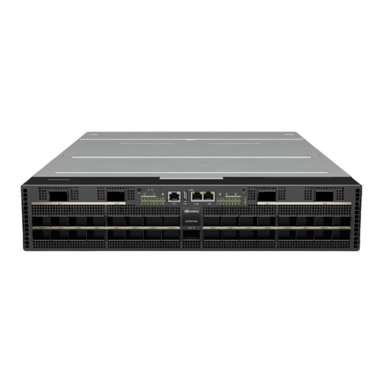
With this powerful combination, they deliver unparalleled performance for handling the most demanding tasks in HPC and AI domains. The NVIDIA Quantum-3 switches are available with internal management capabilities. As a rack-mounted In niBand solution, the NVIDIA Quantum-3 switches provide maximum exibility for various network topologies. - Page 13 Q3200-RA Front View Q3200-RA Rear View Q3400-RA Front View Q3400-RA Rear View Q3200-RA/Q3400-RA XDR 800Gb/s InfiniBand Switch Systems User Manual...
-
Page 14: Speed And Switching Capabilities
FNM - System Fabric Conso Replaceable Replaceable USB and I Model Managem ent Port Front (USB 2.0 Front (2 Q3200-RA Front Front Yes, 4 Yes, 5 type A) ports) Q3200-RA/Q3400-RA XDR 800Gb/s InfiniBand Switch Systems User Manual... -
Page 15: Certi Cations
In niBand > Switch Systems , and select the desired product page. Certi cations The list of certi cations (such as EMC, Safety and others) per system for di erent regions of the world is located on the NVIDIA website at https://www.nvidia.com/en- us/networking/environmental-and-regulatory-compliance/. Q3200-RA/Q3400-RA XDR 800Gb/s InfiniBand Switch Systems User Manual... -
Page 16: Installation
33887290/imag e2022-8-24_15- images/download/thumbnails/3233887290/image 46-8-version-1- 2022-8-24_15-48-2-version-1-modi cationdate- modi cationdat 1728303593677-api-v2.png 172830359386 0-api-v2.png images/downloa images/download/thumbnails/3233887290/image d/thumbnails/32 -2024-1-17_15-42-47-version-1-modi cationdate- 33887290/imag 1728303588167-api-v2.png e-2024-1- 17_15-44-4- version-1- Q3200-RA/Q3400-RA XDR 800Gb/s InfiniBand Switch Systems User Manual... - Page 17 172830358786 3-api-v2.png Note Unless otherwise speci ed, NVIDIA products are designed to work in an environmentally controlled data center with low levels of gaseous and dust (particulate) contamination. The operation environment should meet severity level G1 as per ISA 71.04 for gaseous contamination and ISO 14644-1 class 8...
-
Page 18: Safety Warnings
Note that not all warnings may apply to all models. Switch Safety Warnings (English) Installation Instructions Read all installation instructions before connecting the equipment to the power source. Bodily Injury Due to Weight Use enough people to safely lift this product. Q3200-RA/Q3400-RA XDR 800Gb/s InfiniBand Switch Systems User Manual... - Page 19 8 cm (3 inches) of clearance around the ventilation openings. Stacking the Chassis The chassis should not be stacked on any other equipment. If the chassis falls, it can cause bodily injury and equipment damage. Q3200-RA/Q3400-RA XDR 800Gb/s InfiniBand Switch Systems User Manual...
- Page 20 Equipment Installation This equipment should be installed, replaced, and/or serviced only by trained and quali ed personnel. Equipment Disposal Disposal of this equipment should be in accordance to all national laws and regulations. Q3200-RA/Q3400-RA XDR 800Gb/s InfiniBand Switch Systems User Manual...
- Page 21 US National Electrical Code and the Canadian Electrical Code. Interconnection of Units Cables for connecting to the unit RS232 and Ethernet Interfaces must be UL certi ed type DP-1 or DP-2. (Note: when residing in non LPS circuit.) Q3200-RA/Q3400-RA XDR 800Gb/s InfiniBand Switch Systems User Manual...
- Page 22 Country of Norway Power Restrictions This unit is intended for connection to a TN power system and an IT power system of Norway only. Taiwan RoHS Declaration - Switch Systems Q3200-RA/Q3400-RA XDR 800Gb/s InfiniBand Switch Systems User Manual...
-
Page 23: Nordic Countries Notices
Taiwan RoHS Declaration - Gateway Systems Taiwan BSMI Class A Statement - Warning to the User! , 。 Nordic Countries Notices In Finland: "Laite on liitettävä suojakoskettimilla varustettuun pistorasiaan" Q3200-RA/Q3400-RA XDR 800Gb/s InfiniBand Switch Systems User Manual... - Page 24 In Norway: "Apparatet må tilkoples jordet stikkontakt" In Sweden: "Apparaten skall anslutas till jordat uttag" (Simpli ed Chinese) 。 , 。 , , 。 , 。 。 高 高 。 , , 。 Q3200-RA/Q3400-RA XDR 800Gb/s InfiniBand Switch Systems User Manual...
- Page 25 。 , 。 。 , , 。 。 , 。 。 。 , 。 , 。 , 。 。 、 。 。 。 Q3200-RA/Q3400-RA XDR 800Gb/s InfiniBand Switch Systems User Manual...
- Page 26 、 、 面 , 300 V 250 V, 10 A , 。 , 。 高 高 , 。 , 。 , , 。 RS232 DP-1 DP-2 面 。 非 20 A 。 Q3200-RA/Q3400-RA XDR 800Gb/s InfiniBand Switch Systems User Manual...
- Page 27 、 音 、 风 、 、 OSHA 。 , , 音 , 音 。 。 。 , 。 WEEE WEEE 2002/96/EC (EEE) , , , 。 。 。 China CCC Warning Statement Q3200-RA/Q3400-RA XDR 800Gb/s InfiniBand Switch Systems User Manual...
- Page 28 Taiwan RoHS Declaration - Switch Systems Q3200-RA/Q3400-RA XDR 800Gb/s InfiniBand Switch Systems User Manual...
- Page 29 Taiwan BSMI Class A Statement - Warning to the User! , 。 Caution: Risk of Explosion A risk of explosion exists, if the battery is replaced with an incorrect type. Dispose of used batteries according to the instructions. Q3200-RA/Q3400-RA XDR 800Gb/s InfiniBand Switch Systems User Manual...
- Page 30 。 。 。 。 。 。 (Chinese) 。 , 。 , , 。 风 , 。 风 。 高 高 。 , , 风 。 。 , 。 Q3200-RA/Q3400-RA XDR 800Gb/s InfiniBand Switch Systems User Manual...
- Page 31 。 , 。 , 。 。 。 , 。 , 。 。 , 须 预 。 顶 。 、 。 。 。 Q3200-RA/Q3400-RA XDR 800Gb/s InfiniBand Switch Systems User Manual...
- Page 32 300 V 250 V, , 额 , 。 , 额 10 A 。 高 高 须 , 。 , 。 , , 。 RS232 DP-1 DP-2 面 须 。 20 A 。 音 Q3200-RA/Q3400-RA XDR 800Gb/s InfiniBand Switch Systems User Manual...
- Page 33 、 音 、 风 、 、 OSHA 。 , , 音 , 音 。 。 。 , 。 WEEE WEEE 2002/96/EC (EEE) , , , 。 。 。 China CCC Warning Statement Q3200-RA/Q3400-RA XDR 800Gb/s InfiniBand Switch Systems User Manual...
- Page 34 Taiwan RoHS Declaration - Switch Systems Q3200-RA/Q3400-RA XDR 800Gb/s InfiniBand Switch Systems User Manual...
- Page 35 Taiwan BSMI Class A Statement - Warning to the User! , 。 Caution: Risk of Explosion A risk of explosion exists, if the battery is replaced with an incorrect type. Dispose of used batteries according to the instructions. Q3200-RA/Q3400-RA XDR 800Gb/s InfiniBand Switch Systems User Manual...
-
Page 36: Avertissements De Sécurité Pour L'installation (French)
En outre et pour garantir une circulation d'air correcte, laisser un espace d'au moins 8 cm (3") autour des ori ces de ventilation. Châssis empilé sur d'autres équipements Q3200-RA/Q3400-RA XDR 800Gb/s InfiniBand Switch Systems User Manual... - Page 37 Lors du montage ou de la maintenance de ce produit dans un rack, il faut faire spécialement attention pour s'assurer que l'ensemble reste stable. En règle générale, le rack doit être rempli en commençant par le bas. Installation de l'équipement Q3200-RA/Q3400-RA XDR 800Gb/s InfiniBand Switch Systems User Manual...
- Page 38 300 V, avec une gaine isolante en PVC. Le cordon doit avoir une prise moulée 250 V 10 A. Courant de fuite élevé Avertissement: courant de fuite élevé, une connexion à la terre est indispensable avant de brancher l'alimentation. Q3200-RA/Q3400-RA XDR 800Gb/s InfiniBand Switch Systems User Manual...
- Page 39 Les rails ne sont pas destinés à faire coulisser l'unité hors du rack. Ils sont destinés à une installation permanente à l'emplacement nal, pas pour l'entretien ni la maintenance. Directive DEEE Q3200-RA/Q3400-RA XDR 800Gb/s InfiniBand Switch Systems User Manual...
-
Page 40: Installation Sicherheitshinweise (German)
Temperatur betrieben werden. Es ist ein Luftstrom von 200 LFM bei maximaler Umgebungstemperatur erforderlich. Außerdem sollten mindestens 8 cm (3 in.) Freiraum um die Belüftungsö nungen sein, um einen einwandfreien Luftstrom zu gewährleisten. Q3200-RA/Q3400-RA XDR 800Gb/s InfiniBand Switch Systems User Manual... - Page 41 Vorsichtsmaßnahmen zu ergreifen, um die Stabilität des Systems zu gewährleisten. Im Allgemeinen sollten Sie das Gestell von unten nach oben mit Geräten füllen. Geräteinstallation Diese Gerät sollte nur von geschultem und quali ziertem Personal installiert, ausgetauscht oder gewartet werden. Q3200-RA/Q3400-RA XDR 800Gb/s InfiniBand Switch Systems User Manual...
- Page 42 300 V, mit einem PVC-Mantel isoliert. Das Kabel muss eine angespritztem Stecker bewertet bei 250 V, 10 A. Hoher Ableitstrom WARNUNG: Hohe Ableitstrom; Earth Verbindung, bevor Sie die Verbindung von wesentlicher Bedeutung werden. Q3200-RA/Q3400-RA XDR 800Gb/s InfiniBand Switch Systems User Manual...
- Page 43 Gestell weg zu ziehen. Sie sind nur für die permanente Installation an einem endgültigen Standort gedacht, nicht für Instandhaltung und Wartung. WEEE-Direktive Gemäß WEEE Directive 2002/96/EC müssen alle elektrischen und elektronischen Abfallgeräte (EEE) separat gesammelt und nichit mit normalem Haushaltsmüll Q3200-RA/Q3400-RA XDR 800Gb/s InfiniBand Switch Systems User Manual...
-
Page 44: Advertencias De Seguridad De Instalación (Spanish)
No se debe utilizar el equipo en un área con una temperatura ambiente superior a la máxima recomendada. Además, para garantizar una circulación de aire adecuada, se debe dejar como mínimo un espacio de 8 cm (3 pulgadas) alrededor de las aberturas de ventilación. Apilamiento del chasis Q3200-RA/Q3400-RA XDR 800Gb/s InfiniBand Switch Systems User Manual... - Page 45 Al instalar o realizar el mantenimiento de este aparato en un bastidor, es preciso adoptar precauciones especiales para garantizar que el sistema se mantenga estable. En general, en un bastidor, los equipos se deben instalar comenzando desde abajo hacia arriba. Instalación del equipo Q3200-RA/Q3400-RA XDR 800Gb/s InfiniBand Switch Systems User Manual...
- Page 46 "<HAR>", de tres conductores, hilo de 1,0 mm2 como mínimo, 300 voltios nominal, con cobertura protectora aislante de PVC. El cable debe tener un enchufe moldeado con capuchón de 250 voltios nominal, 10 A. Alta corriente de fuga Q3200-RA/Q3400-RA XDR 800Gb/s InfiniBand Switch Systems User Manual...
- Page 47 La nalidad de los rieles no es deslizar la unidad hacia afuera del bastidor. Sirven solo para la instalación permanente en el lugar de destino nal, no para nes de servicio o mantenimiento Directiva WEEE Q3200-RA/Q3400-RA XDR 800Gb/s InfiniBand Switch Systems User Manual...
-
Page 48: Предупреждения По Технике Безопасности При Установке (Russian)
существует возможность повреждения контактов питания в его углублении. НЕ вставлять инструменты или части тела в углубление вентиляторного модуля. Перегрев Не эксплуатировать это оборудование в помещении с температурой окружающей среды, превышающей максимально рекомендуемое значение. Более того, для Q3200-RA/Q3400-RA XDR 800Gb/s InfiniBand Switch Systems User Manual... - Page 49 Подсоединение и отсоединение медных кабелей Медные кабели тяжелые и негибкие, поэтому следует осторожно их подсоединять и отсоединять. За особыми предупреждениями и указаниями следует обратиться к производителю кабеля. Установка или обслуживание в стойке Q3200-RA/Q3400-RA XDR 800Gb/s InfiniBand Switch Systems User Manual...
- Page 50 неправильного типа. Отработавшие аккумуляторы утилизируются в соответствии с указаниями. Шнур питания, включенный в номенклатуру UL и сертифицированный Канадской ассоциацией стандартизации (CSA) Подключение к электропитанию в Северной Америке выполняется с помощью шнура питания, включенного в номенклатуру UL и сертифицированного Q3200-RA/Q3400-RA XDR 800Gb/s InfiniBand Switch Systems User Manual...
- Page 51 собой создаваемый изделием уровень шума, измеренный в соответствии со стандартом ISO 7779 в номинальных условиях. Фактический уровень шума может варьироваться в зависимости от условий установки, включая (но не ограниваясь этими данными) количество стоек в установке, общий размер установки, материалы, Q3200-RA/Q3400-RA XDR 800Gb/s InfiniBand Switch Systems User Manual...
-
Page 52: Avertismente Privind Siguranţa La Instalare (Romanian)
Avertismente privind siguranţa la instalare (Romanian) Instrucţiuni de instalare Citiţi toate instrucţiunile de instalare înainte de a conecta. Accidentare cauzată de greutate Apelaţi la un număr su cient de persoane pentru a ridica în siguranţă acest produs. Q3200-RA/Q3400-RA XDR 800Gb/s InfiniBand Switch Systems User Manual... - Page 53 Risc de şoc electric şi pericol electric. Toate aparatele cu alimentare de la reţea sunt independente. Deconectaţi toate sursele de alimentare cu energie pentru a asigura decuplarea în interiorul platformei de comutare. Q3200-RA/Q3400-RA XDR 800Gb/s InfiniBand Switch Systems User Manual...
- Page 54 Acest dispozitiv trebuie să e instalat în conformitate cu ultima versiune a codurilor electrice naţionale ale ţării în cauză. Pentru America de Nord, echipamentul trebuie să e instalat conform cerințelor aplicabile din Codul electric naţional al SUA şi Codul electric canadian. Înlocuirea bateriei Q3200-RA/Q3400-RA XDR 800Gb/s InfiniBand Switch Systems User Manual...
- Page 55 Protecţie la supracurent: Un dispozitiv de protecţie la supracurent, înregistrat în circuitul de rami care, uşor accesibil şi cu o putere nominală egală cu 20 A trebuie să e integrat în cablajul clădirii. Avertizare privind nivelul acustic Q3200-RA/Q3400-RA XDR 800Gb/s InfiniBand Switch Systems User Manual...
-
Page 56: Sigurnosna Upozorenja Za Instaliranje (Croatian)
This unit is intended for connection to a TN power system and an IT power system of Norway only. Sigurnosna upozorenja za instaliranje (Croatian) Upute za instaliranje Pažljivo pročitajte upute za instaliranje prije spajanja opreme na izvor električne energije. Tjelesne ozljede uslijed težine Q3200-RA/Q3400-RA XDR 800Gb/s InfiniBand Switch Systems User Manual... - Page 57 Redundantno napajanje - Opasnost od električne energije Ovaj proizvod uključuje redundantno napajanje ili prazan prostor na njegovu mjestu. U slučaju praznog prostora za napajanje, nemojte rukovati proizvodom ako je poklopac uklonjen ili ako nije dobro pričvršćen. Dvopolni/neutralni osigurači Q3200-RA/Q3400-RA XDR 800Gb/s InfiniBand Switch Systems User Manual...
- Page 58 Odlaganje opreme trebalo bi se vršiti sukladno nacionalnim zakonima i propisima. Lokalni i nacionalni električni kodovi Ova oprema trebala bi se instalirati u skladu s lokalnim i nacionalnim električnim kodovima. Instalacijski kodovi Q3200-RA/Q3400-RA XDR 800Gb/s InfiniBand Switch Systems User Manual...
- Page 59 DP-1 ili DP-2. (Napomena - kad se nalazi u krugu bez LPS vodiča). Zaštita od strujnog preopterećenja: Uvijek dostupni odobreni zaštitni uređaji od strujnog preopterećenja nazivne struje od 20 A moraju se ugraditi u ožičenje zgrade. Q3200-RA/Q3400-RA XDR 800Gb/s InfiniBand Switch Systems User Manual...
-
Page 60: Avvertenze Di Sicurezza Per L'installazione (Italian)
Istruzioni di installazione Leggere tutte le istruzioni di installazione prima di collegare l’apparecchiatura all’alimentazione. Lesioni a causa del peso Usare un numero di persone su ciente per sollevare in sicurezza questo prodotto. Q3200-RA/Q3400-RA XDR 800Gb/s InfiniBand Switch Systems User Manual... - Page 61 Fusibili fase/neutro Questo sistema dispone di fusibili fase/neutro. Rimuovere tutti i cavi di alimentazione prima di aprire il coperchio di questo prodotto o di toccare parti interne. Q3200-RA/Q3400-RA XDR 800Gb/s InfiniBand Switch Systems User Manual...
- Page 62 Lo smaltimento di questa apparecchiatura va e ettuato in conformità con tutte le leggi e le normative nazionali. Codici elettrici locali e nazionali Questa apparecchiatura va installata in conformità con le norme elettriche locali e nazionali. Q3200-RA/Q3400-RA XDR 800Gb/s InfiniBand Switch Systems User Manual...
- Page 63 Interconnessione delle unità I cavi per il collegamento all’unità RS232 e alle interfacce Ethernet devono disporre della certi cazione UL ed essere del tipo DP-1 o DP-2. (Nota: in caso di installazione su Q3200-RA/Q3400-RA XDR 800Gb/s InfiniBand Switch Systems User Manual...
-
Page 64: Montaj Güvenlik Uyarıları (Turkish)
Limitazioni relative all’alimentazione per la Norvegia Questa apparecchiatura è progettata esclusivamente per il collegamento a un sistema di alimentazione TN e a un sistema di alimentazione IT. Montaj Güvenlik Uyarıları (Turkish) Q3200-RA/Q3400-RA XDR 800Gb/s InfiniBand Switch Systems User Manual... - Page 65 Yedekli Güç Kaynaðý Baðlantýsý -Elektrik Çarpma Tehlikesi Bu ürün, yedekli güç kaynağı veya onun yerine boş elektrik kutusu içerir. Güç kaynağı için boş elektrik kutusu varsa, kutunun kapağı açıkken veya tam olarak Q3200-RA/Q3400-RA XDR 800Gb/s InfiniBand Switch Systems User Manual...
- Page 66 Ekipmanın Atılması Bu ekipmanın imhasında tüm ulusal yasalara ve düzenlemelere uyulması gerekir. Yerel ve Ulusal Elektrik Kodları Bu ekipmanın montajında yerel ve ulusal elektrik kodlarına uyulması gerekir. Montaj Kodları Q3200-RA/Q3400-RA XDR 800Gb/s InfiniBand Switch Systems User Manual...
- Page 67 DP-2 tipi olması gerekir. (Not- LPS olmayan devreye aitse). Aşırı Akım Koruması: Kolayca erişilebilecek 20 V Kayıtlı devre parçası aşırı akım koruma cihazının bina elektrik şebekesinde kurulu olması gerekir. Akustik Seviye Uyarısı Q3200-RA/Q3400-RA XDR 800Gb/s InfiniBand Switch Systems User Manual...
-
Page 68: Japan Vcci Statement
Bu ünite, bir TN güç sistemine ve sadece Norveç'in IT güç sistemine bağlanmak içindir. Japan VCCI Statement (Hebrew) הוראות בטיחות בהתקנה הוראות התקנה .קרא היטב את כל הוראות ההתקנה לפני חיבור המוצר לחשמל Q3200-RA/Q3400-RA XDR 800Gb/s InfiniBand Switch Systems User Manual... - Page 69 .בנוסף, כדי להבטיח כניסת אוויר תקינה, יש לוודא כי קיים שטח פנוי של 8 ס”מ )3 אינץ’( לפחות סביב פתחי האוורור ערימת המערכת .אין לערום את המערכת על גבי ציוד אחר. במקרה של נפילה, עשויים להגרם נזקי גוף ורכוש חיבור ספק כוח נוסף -סכנת התחשמ Q3200-RA/Q3400-RA XDR 800Gb/s InfiniBand Switch Systems User Manual...
- Page 70 .כל התקנה, החלפה או טיפול במוצר זה חייבות להתבצע על ידי איש צוות מיומן ומוסמך בלבד השלכה לאשפה בתום השימוש .השלכת המוצר בתום השימוש חייבת להיעשות בהתאם לכל התקנות והחוקים המקומיים תקנות חשמל מקומיות .יש להתקין מערכת זו בהתאם לתקנות החשמל המקומיות כבל אספקת חשמל Q3200-RA/Q3400-RA XDR 800Gb/s InfiniBand Switch Systems User Manual...
- Page 71 בתנאים נומינליים. רמת הרעש בפועל עשויה להשתנות בהתאם לתנאי ההתקנה, הכוללים אך לא מוגבלים למספר הכונניות בהתקנה, היקף ההתקנה הכולל, החומרים שמהם עשויות הכונניות ועשוי שאר הציוד, וכן רמות רעש, תקלות מאוורר, טמפרטורת ותצורת החדר ומיקום העובד ביחס לציוד. על האחראי על מרכז הנתונים Q3200-RA/Q3400-RA XDR 800Gb/s InfiniBand Switch Systems User Manual...
- Page 72 .IT , ולמערכת אספקת חשמל מסוגTN בנורבגיה בלבד, יחידה זו מיועדת לחיבור למערכת אספקת חשמל מסוג Air Flow Currently, the NVIDIA XDR systems are o ered with one air ow pattern: Connector (front) side inlet to power side outlet - marked with red dots that are placed on the power inlet side.
-
Page 73: Package Contents
If anything is damaged or missing, contact your sales representative at Networking-support@nvidia.com. 19” System Mounting Options By default, the Q3200-RA and Q3400-RA systems are shipped with the rail kits described in Q3200-RA Tool-Less Rail Kit and Q3400-RA Tool-Less Rail Kit, respecivly. Q3200-RA/Q3400-RA XDR 800Gb/s InfiniBand Switch Systems User Manual... -
Page 74: Q3200-Ra Tool-Less Rail Kit
NVIDIA representative at Networking- support@nvidia.com. The following parts are included in the tool-less rail kit (see gure below): 2x System Rails (A) 2x Rack Rails (B) Rail Kit Parts Left: Right: Q3200-RA/Q3400-RA XDR 800Gb/s InfiniBand Switch Systems User Manual... - Page 75 Consider this when planning the switch installation.| Note The following steps include illustrations that show front side (ports) installation, yet all instructions apply to all installation options. Q3200-RA/Q3400-RA XDR 800Gb/s InfiniBand Switch Systems User Manual...
- Page 76 Angularly Inserting the Brakes Located at the Rails Edges into the Designated Slots in the Rack Unit Q3200-RA/Q3400-RA XDR 800Gb/s InfiniBand Switch Systems User Manual...
- Page 77 A click should be heard as the spring latches are fully inserted and locking occurs. Aligning Both Rack Rails to Sit Horizontally in Parallel to the Rack Assembly Q3200-RA/Q3400-RA XDR 800Gb/s InfiniBand Switch Systems User Manual...
- Page 78 6. Tighten the captive screws on both sides to further secure the system to the rack's posts. Q3200-RA/Q3400-RA XDR 800Gb/s InfiniBand Switch Systems User Manual...
- Page 79 4. Remove the rails from the system. Release the metal latches and pull out the rails, so the system's pins will be removed out of the designated slots. Pressing the Locking Buttons and Pulling the System Out Q3200-RA/Q3400-RA XDR 800Gb/s InfiniBand Switch Systems User Manual...
- Page 80 Removing the Rails from the System Q3200-RA/Q3400-RA XDR 800Gb/s InfiniBand Switch Systems User Manual...
-
Page 81: Q3400-Ra Tool-Less Rail Kit
If anything is missing or damaged, contact your NVIDIA representative at Networking- support@nvidia.com. The following parts are included in the tool-less rail kit (see gure below): Q3200-RA/Q3400-RA XDR 800Gb/s InfiniBand Switch Systems User Manual... - Page 82 The following steps details the installation process: 1. Install both rack rails (A) by inserting their pins to the designated key holes in the rack, and aligning them in an angular position. Q3200-RA/Q3400-RA XDR 800Gb/s InfiniBand Switch Systems User Manual...
- Page 83 Inserting the Rack Rails (A) and Aligning them in an Angular Position 2. Secure the assembly by gently pushing the rails' pins through the slider key holes, until locking occurs. Rack Rails Fully Inserted and Locked in the Rack Assembly Q3200-RA/Q3400-RA XDR 800Gb/s InfiniBand Switch Systems User Manual...
- Page 84 4. Attach the system rails (B) to the system. Align the central mushroom pin circled below with your selection. Attaching the System Rails to the Switch Chassis Flush Recessed To mount the system into the rack: Q3200-RA/Q3400-RA XDR 800Gb/s InfiniBand Switch Systems User Manual...
- Page 85 Tightening the Captive Screws Once the system is fully secured in the rack, install the two Black Cubes (C) on the back of the rack rail as shown, and tighen the two captive screws: Q3200-RA/Q3400-RA XDR 800Gb/s InfiniBand Switch Systems User Manual...
- Page 86 2. Loosen back captive screws and remove Black cubes (C). 3. Loosen front captive screws and pull the system out. Warning This is a heavy system. Server lift is required to support the system weight safely. Pulling the System Out Q3200-RA/Q3400-RA XDR 800Gb/s InfiniBand Switch Systems User Manual...
- Page 87 To release the rack rails, press the locking buttons on both sides and slightly push the rail towards the inside of the cabinet until the the rail pins removed out from the rack post holes. Pressing the Locking Buttons on Both Sides Q3200-RA/Q3400-RA XDR 800Gb/s InfiniBand Switch Systems User Manual...
-
Page 88: Cable Installation
Removing the Rails from the System Warning Make sure the system rails latch is fully locked onto the system mushroom pin (see below image). images/download/thumbnails/3201684823/image-2024-11- 4_15-12-52-version-1-modi cationdate-1730729572473-api- v2.png Cable Installation Power Cable and Cable Retainer Q3200-RA/Q3400-RA XDR 800Gb/s InfiniBand Switch Systems User Manual... - Page 89 For demonstration purposes, the images in this document show C2P (Connector-to-Power) air ow PSUs with red latches, yet the instructions apply to P2C (Power-to-Connector) PSUs with blue latches as well. Correct Insertion Incorrect Insertion Q3200-RA/Q3400-RA XDR 800Gb/s InfiniBand Switch Systems User Manual...
- Page 90 Incorrect Insertion 3. Push the retainer until the shoulders' pins (in blue circles below) are open and aligned with the PSU front panel, as shown in the following table: Fully Mated Retainer Q3200-RA/Q3400-RA XDR 800Gb/s InfiniBand Switch Systems User Manual...
-
Page 91: Port Cables
To insert a cable, press the connector into the port receptacle until the connector is rmly seated. The LED indicator, corresponding to each data port, will light when the physical connection is established. When a logical connection is made, the relevant port LED will turn on. Q3200-RA/Q3400-RA XDR 800Gb/s InfiniBand Switch Systems User Manual... - Page 92 To remove a cable, disengage the locks and slowly pull the connector away from the port receptacle. The LED indicator for that port will turn o when the cable is unseated. For full cabling guidelines, ask your NVIDIA representative for a copy of NVIDIA Cable Management Guidelines and FAQs Application Note.
- Page 93 . When you disconnect the cable marked as “2”, the CLI <cage number>/2 will always go down, and the right LED of the cage will be turned o . Breakout Cable Example Q3200-RA/Q3400-RA XDR 800Gb/s InfiniBand Switch Systems User Manual...
- Page 94 Q3200-RA Splitting Options The following diagram shows ASIC A and ASIC B, as well as the cage numbers. Each cage splits into two. For example : ASIC A/Cage1/ has both Port1 and Port2: Q3200-RA/Q3400-RA XDR 800Gb/s InfiniBand Switch Systems User Manual...
-
Page 95: Initial Power On
The following diagram shows the ASIC/Cage/Port/Split numbering: Port Notation Schematics for Q3400-RA Cage/Port pro le : Logical Port Numbering Schematic Initial Power On Each system’s input voltage is speci ed in the Speci cations chapter. Q3200-RA/Q3400-RA XDR 800Gb/s InfiniBand Switch Systems User Manual... - Page 96 (initially ashing, and then moving to a steady color) as shown below. For more information, refer to LED Noti cations. System Status LEDs 5 Minutes After Power On Q3200: Q3200-RA/Q3400-RA XDR 800Gb/s InfiniBand Switch Systems User Manual...
- Page 97 Risk of electric shock and energy hazard. The power supply units are independent. Disconnect all power supplies to ensure a powered down state inside of the switch platform. ACHTUNG Gafahr des elektrischen Schocks. Entferrnen des Netzsteckers elnes Netzteils spannungsfrei. Um alle Einhieten Q3200-RA/Q3400-RA XDR 800Gb/s InfiniBand Switch Systems User Manual...
-
Page 98: System Bring-Up Of Managed Systems
System Bring-Up of Managed Systems This quick start guide provides an end-to-end setup process for installing and running NVOS. Note Before running NVUE commands, please refer to the NVIDIA User Experience (NVUE) section in the NVIDIA NVOS User Manual for In niBand Switches. Note NVOS supports con gurations through NVUE only. -
Page 99: Get Started
Get Started NVOS provides two methods for initial provisioning: Zero-Touch Provisioning (ZTP) (for more information, see the Zero-Touch Provisioning section in the NVIDIA NVOS User Manual for In niBand Switches) Manual Provisioning Manual Provisioning When starting NVOS for the rst time, the management port send a DHCP request. To determine the IP address of the switch, you can cross reference the MAC address of the switch with your DHCP server. - Page 100 Upon rst login, it will be required to change the default passwords for the admin and monitor accounts. The new password must comply with the default password hardening rules (see Password Hardening section in the NVIDIA NVOS User Manual for In niBand Switches).
-
Page 101: Serial Console Management
To set a static IP address, run the following (ipv6 supported as well): admin :~$ nv set eth0 ip address @nvos interface 192.0 2.42 admin :~$ nv set eth0 ip gateway @nvos interface 192.0 admin :~$ nv config apply @nvos Q3200-RA/Q3400-RA XDR 800Gb/s InfiniBand Switch Systems User Manual... - Page 102 Con gure the Hostname The hostname identi es the switch; as such, make sure the hostname is con gured in a unique and descriptive way. For more information, see Hostname section in the NVIDIA NVOS User Manual for In niBand Switches.
- Page 103 @nvos 2024 NVOS supports Network Time Protocol (NTP) for synchronizing the time of the system. For more information see Network Time Protocol section in the NVIDIA NVOS User Manual for In niBand Switches NTP Servers from DHCP By default, NTP will obtain the NTP servers from DHCP. It is possible to disable it by...
- Page 104 NTP server must use the same key. NVOS support various attributes for NTP servers and keys, for more infomation please see NTP Commands section in the NVIDIA NVOS User Manual for In niBand Switches. Con gure Syslog Servers User can con gure the system to send syslog logs to a centralized logging server ( one or...
-
Page 105: Fru Replacements
Con gure Connection-Mode In an In niBand Interface The connection-mode attribute indicates to which peer this port is connected. This feature is dedicated to Q3200-RA system which can be connected to NDR systems (or older) and to XDR systems. In case the port is connected to XDR systems, the connection-mode should be XDR. If it connected to NDR system, the connection-mode should be NDR. - Page 106 2. Grasping the handle with your hand, push the latch release with your thumb while pulling the handle outward. As the power supply unit unseats, the power supply unit status LEDs will turn o . 3. Remove the power supply unit. PS Unit Pulled Out Q3200-RA/Q3400-RA XDR 800Gb/s InfiniBand Switch Systems User Manual...
- Page 107 2. Insert the power supply unit by sliding it into the opening, until a slight resistance is felt. 3. Continue pressing the power supply unit until it seats completely. The latch will snap into place, con rming the proper installation. Q3200-RA/Q3400-RA XDR 800Gb/s InfiniBand Switch Systems User Manual...
- Page 108 60 seconds. 1. Extract the fan by pulling the gold handle outwards. As the fan unit unseats, its status LEDs will turn o . Q3200-RA/Q3400-RA XDR 800Gb/s InfiniBand Switch Systems User Manual...
- Page 109 The green Fan Status LED should light. If not, extract the fan unit and reinsert it. After two unsuccessful attempts to install the fan unit, power o the system before attempting any system debug. Q3200-RA/Q3400-RA XDR 800Gb/s InfiniBand Switch Systems User Manual...
-
Page 110: Nvos
Documentation for NVOS will be available via the NVONLINE system. For more information on software management, refer to NVIDIA NVOS User Manual for In niBand Switches. Q3200-RA/Q3400-RA XDR 800Gb/s InfiniBand Switch Systems User Manual... -
Page 111: Interfaces
Speed and Switching Capabilities. Each OSFP port consists of 4 logical In niBand ports, and can be connected with OSFP cable or connector for 40/56/100/200/400/800Gb/s in Q3200-RA, and for 400/800Gb/s in Q3400-RA. The systems o er Class 8 (33W) OSFP224 transceivers support. -
Page 112: Rs232 (Console)
In niBand speed is auto-adjusted by the In niBand protocol. NVIDIA systems support QDR/FDR/EDR/HDR/NDR/XDR In niBand. FDR is an In niBand data rate, where each lane of a 4X port runs a bit rate of 14.0625Gb/s with 64b/66b encoding, resulting in an e ective bandwidth of 56.25Gb/s. - Page 113 The USB interface is USB 2.0 type A compliant and can be used by MLNX-OS software to connect to an external disk for software upgrade or le management. Note USB 1.0 is not supported. Q3200-RA/Q3400-RA XDR 800Gb/s InfiniBand Switch Systems User Manual...
- Page 114 Only FAEs are authorized to connect through it. Warning Only original NVIDIA cables supplied with the switch package can be used to connect a switch system to the server. Connecting any cable other than the NVIDIA supplied console cable may cause an I²C hang.
- Page 115 Since the FNM port is semi-populated (only the rst four lanes of it are wired), it functions as an HDR port. Q3200 Air Cooled - Non-planarized FNM Port (Hardware Limited to 2x100 Con guration) Mode NDR SM - Single FNM side Mode** Q3200-RA/Q3400-RA XDR 800Gb/s InfiniBand Switch Systems User Manual...
- Page 116 Q3200 Air Cooled - Non-planarized FNM Port (Hardware Limited to 2x100 Con guration) Q3200-RA/Q3400-RA XDR 800Gb/s InfiniBand Switch Systems User Manual...
- Page 117 Q3200 Air Cooled - Non-planarized FNM Port (Hardware Limited to 2x100 Con guration) NDR SM - Single UFM 3.5 side Mode** NDR MM** FNM side Q3200-RA/Q3400-RA XDR 800Gb/s InfiniBand Switch Systems User Manual...
- Page 118 Q3200 Air Cooled - Non-planarized FNM Port (Hardware Limited to 2x100 Con guration) NDR MM* UFM 3.5 side XDR SM -Single FNM side Mode** Q3200-RA/Q3400-RA XDR 800Gb/s InfiniBand Switch Systems User Manual...
- Page 119 Q3200 Air Cooled - Non-planarized FNM Port (Hardware Limited to 2x100 Con guration) XDR SM - Single UFM 3.5 side Mode* * UFM3.5 con gures the C8180 cards to be non-planarized. Q3200-RA/Q3400-RA XDR 800Gb/s InfiniBand Switch Systems User Manual...
-
Page 120: Reset Button
Warning Do not use a sharp pointed object such as a needle or a push pin for pressing the reset button. Use a at object to push the reset button. Q3200-RA/Q3400-RA XDR 800Gb/s InfiniBand Switch Systems User Manual... -
Page 121: Led Noti Cations
“admin”. LEDs See LED Noti cations. LED Noti cations The system’s LEDs are an important tool for hardware event noti cation and troubleshooting. LEDs Symbols Symbol Name System Status LED Q3200-RA/Q3400-RA XDR 800Gb/s InfiniBand Switch Systems User Manual... - Page 122 Power Supply Units LEDs Q3200-RA/Q3400-RA XDR 800Gb/s InfiniBand Switch Systems User Manual...
- Page 123 Fan Status LED Unit Identi er LED Q3200-RA/Q3400-RA XDR 800Gb/s InfiniBand Switch Systems User Manual...
-
Page 124: System Status Led
It may take up to ve minutes to turn on the system. If the System Status LED shows amber after ve minutes, unplug the system and call your NVIDIA representative for assistance. System Status LED Assignments Q3200-RA/Q3400-RA XDR 800Gb/s InfiniBand Switch Systems User Manual... -
Page 125: Fan Status Led
NVIDIA representative for system is overheated, etc. assistance. Fan Status LED Fan Status LED - Front and Rear Sides (marked red) Front Panel Rear Panel Q3200 Q3400 Q3200-RA/Q3400-RA XDR 800Gb/s InfiniBand Switch Systems User Manual... - Page 126 Action Required Behavior Solid Green A speci c fan unit is operating. Solid A speci c fan unit is missing or not operating The fan unit should be Amber properly. replaced. Warning Q3200-RA/Q3400-RA XDR 800Gb/s InfiniBand Switch Systems User Manual...
-
Page 127: Power Supply Status Leds
Each power supply unit has a single 2 color LED that indicates the status of the unit. Power Status LED (marked red) Front Panel Rear Panel Q3200 Q3400 Power Supply Unit Status Front LED Assignments Q3200-RA/Q3400-RA XDR 800Gb/s InfiniBand Switch Systems User Manual... - Page 128 Unit Identi cation LED The UID LED is a debug feature, that the user can use to nd a particular system within a cluster by turning on the UID blue LED. Q3200-RA/Q3400-RA XDR 800Gb/s InfiniBand Switch Systems User Manual...
- Page 129 Link is up with no Solid Green tra c. Flashing Link is up with tra c. N/A Green Wait for the Logical link to raise. Check that the Solid Amber Link is up. SM is up. Q3200-RA/Q3400-RA XDR 800Gb/s InfiniBand Switch Systems User Manual...
- Page 130 The system supports an additional OSFP port - FNM (Fabric Network Management). This port has a dedicated LED, as shown in the below gure. Q3200-RA Q3400-RA Port LEDs: Port LEDs: FNM LED: FNM LED: Q3200-RA/Q3400-RA XDR 800Gb/s InfiniBand Switch Systems User Manual...
-
Page 131: Inventory Pull-Out Tab
Inventory Pull-out Tab The system’s inventory parameters (such as serial number, part number and GUID address) can be extracted from the inventory pull-out tab on the upper left side of the rear panel. Q3200-RA/Q3400-RA XDR 800Gb/s InfiniBand Switch Systems User Manual... - Page 132 Pull-out Tab Q3200-RA: Q3400-RA: Note Q3200-RA/Q3400-RA XDR 800Gb/s InfiniBand Switch Systems User Manual...
- Page 133 The images provided here are for illustration purposes only. The may not re ect the latest version of the product nor all available models. Q3200-RA/Q3400-RA XDR 800Gb/s InfiniBand Switch Systems User Manual...
-
Page 134: Troubleshooting
System Status LED is blinking for more than 5 minutes Cause: MLNX- softwa re did boot properl y and only rmwa re is runnin Solutio Conne ct to system via the consol e port, check softwa status. might need contac Q3200-RA/Q3400-RA XDR 800Gb/s InfiniBand Switch Systems User Manual... - Page 135 Cause Problem Indicator Symptoms Solutio t an FAE if MLNX- softwa re did load properl System Status LED is amber Cause: Q3200-RA/Q3400-RA XDR 800Gb/s InfiniBand Switch Systems User Manual...
- Page 136 Cause Problem Indicator Symptoms Solutio Solutio Q3200-RA/Q3400-RA XDR 800Gb/s InfiniBand Switch Systems User Manual...
- Page 137 Cause Problem Indicator Symptoms Solutio Fan Status LED is amber Cause: Possibl e fan issue Solutio Q3200-RA/Q3400-RA XDR 800Gb/s InfiniBand Switch Systems User Manual...
- Page 138 Cause Problem Indicator Symptoms Solutio Q3200-RA/Q3400-RA XDR 800Gb/s InfiniBand Switch Systems User Manual...
- Page 139 Cause Problem Indicator Symptoms Solutio Front PSU Status LED is amber Cause: Possibl e PSU issue Solutio Q3200-RA/Q3400-RA XDR 800Gb/s InfiniBand Switch Systems User Manual...
- Page 140 Cause Problem Indicator Symptoms Solutio Make sure that there is an The activity LED does not light up (In niBand) runnin g in fabric. Q3200-RA/Q3400-RA XDR 800Gb/s InfiniBand Switch Systems User Manual...
- Page 141 Cause Problem Indicator Symptoms Solutio System boot failure The last software upgrade failed on x86 based systems Solutio Q3200-RA/Q3400-RA XDR 800Gb/s InfiniBand Switch Systems User Manual...
- Page 142 Cause Problem Indicator Symptoms Solutio ’s Q3200-RA/Q3400-RA XDR 800Gb/s InfiniBand Switch Systems User Manual...
- Page 143 Cause Problem Indicator Symptoms Solutio Q3200-RA/Q3400-RA XDR 800Gb/s InfiniBand Switch Systems User Manual...
- Page 144 Cause Problem Indicator Symptoms Solutio Q3200-RA/Q3400-RA XDR 800Gb/s InfiniBand Switch Systems User Manual...
- Page 145 Cause Problem Indicator Symptoms Solutio Q3200-RA/Q3400-RA XDR 800Gb/s InfiniBand Switch Systems User Manual...
- Page 146 Cause Problem Indicator Symptoms Solutio Q3200-RA/Q3400-RA XDR 800Gb/s InfiniBand Switch Systems User Manual...
- Page 147 Cause Problem Indicator Symptoms Solutio Q3200-RA/Q3400-RA XDR 800Gb/s InfiniBand Switch Systems User Manual...
- Page 148 Cause Problem Indicator Symptoms Solutio Q3200-RA/Q3400-RA XDR 800Gb/s InfiniBand Switch Systems User Manual...
- Page 149 Cause Problem Indicator Symptoms Solutio Q3200-RA/Q3400-RA XDR 800Gb/s InfiniBand Switch Systems User Manual...
- Page 150 Cause Problem Indicator Symptoms Solutio Q3200-RA/Q3400-RA XDR 800Gb/s InfiniBand Switch Systems User Manual...
- Page 151 Cause Problem Indicator Symptoms Solutio Q3200-RA/Q3400-RA XDR 800Gb/s InfiniBand Switch Systems User Manual...
- Page 152 Cause Problem Indicator Symptoms Solutio Q3200-RA/Q3400-RA XDR 800Gb/s InfiniBand Switch Systems User Manual...
- Page 153 Cause Problem Indicator Symptoms Solutio Q3200-RA/Q3400-RA XDR 800Gb/s InfiniBand Switch Systems User Manual...
- Page 154 Cause Problem Indicator Symptoms Solutio Q3200-RA/Q3400-RA XDR 800Gb/s InfiniBand Switch Systems User Manual...
- Page 155 Cause Problem Indicator Symptoms Solutio Q3200-RA/Q3400-RA XDR 800Gb/s InfiniBand Switch Systems User Manual...
- Page 156 Cause Problem Indicator Symptoms Solutio Q3200-RA/Q3400-RA XDR 800Gb/s InfiniBand Switch Systems User Manual...
- Page 157 Cause Problem Indicator Symptoms Solutio Q3200-RA/Q3400-RA XDR 800Gb/s InfiniBand Switch Systems User Manual...
- Page 158 Cause Problem Indicator Symptoms Solutio Q3200-RA/Q3400-RA XDR 800Gb/s InfiniBand Switch Systems User Manual...
- Page 159 Cause Problem Indicator Symptoms Solutio Q3200-RA/Q3400-RA XDR 800Gb/s InfiniBand Switch Systems User Manual...
- Page 160 Cause Problem Indicator Symptoms Solutio Q3200-RA/Q3400-RA XDR 800Gb/s InfiniBand Switch Systems User Manual...
- Page 161 Cause Problem Indicator Symptoms Solutio " Q3200-RA/Q3400-RA XDR 800Gb/s InfiniBand Switch Systems User Manual...
- Page 162 Cause Problem Indicator Symptoms Solutio Q3200-RA/Q3400-RA XDR 800Gb/s InfiniBand Switch Systems User Manual...
- Page 163 Cause Problem Indicator Symptoms Solutio Q3200-RA/Q3400-RA XDR 800Gb/s InfiniBand Switch Systems User Manual...
-
Page 164: Speci Cations
Speci cations Q3200-RA Technical Speci cations Feature Mechanical Size 4” 7” Q3200-RA/Q3400-RA XDR 800Gb/s InfiniBand Switch Systems User Manual... - Page 165 Feature 9” Mounting Weight Connector cage: Q3200-RA/Q3400-RA XDR 800Gb/s InfiniBand Switch Systems User Manual...
- Page 166 Feature Environmental Temperature 0° 5° 0° Q3200-RA/Q3400-RA XDR 800Gb/s InfiniBand Switch Systems User Manual...
- Page 167 Feature 0° Humidity Q3200-RA/Q3400-RA XDR 800Gb/s InfiniBand Switch Systems User Manual...
- Page 168 Feature Altitude Noise level Q3200-RA/Q3400-RA XDR 800Gb/s InfiniBand Switch Systems User Manual...
- Page 169 Feature Regulatory Safety RoHS Q3200-RA/Q3400-RA XDR 800Gb/s InfiniBand Switch Systems User Manual...
- Page 170 Feature Power Input Voltage Global Power Consumption Q3200-RA/Q3400-RA XDR 800Gb/s InfiniBand Switch Systems User Manual...
- Page 171 Feature Main Devices Switch Q3200-RA/Q3400-RA XDR 800Gb/s InfiniBand Switch Systems User Manual...
- Page 172 Feature Throughput Switching Speed Q3200-RA/Q3400-RA XDR 800Gb/s InfiniBand Switch Systems User Manual...
- Page 173 Non-Operational: -40° to 70°C Environmenta Operational: 10%-85% non-condensing Humidity Non-Operational: 10%-90% non-condensing Altitude 3050m Noise level 78.4dBA at room temperature Safety CB, cTUVus, CE, CU Regulatory EMC: CE, FCC, VCCI, ICES, RCM RoHS RoHS compliant Q3200-RA/Q3400-RA XDR 800Gb/s InfiniBand Switch Systems User Manual...
- Page 174 200-240Vac, 10A, 50/60Hz per PSU Power Global Power Typical power with passive cables (ATIS): 2.9KW Consumption Max power with active cables: 7KW Intel Main Devices Switch Quantum-3 Switching 115.2 Tbps Throughput Speed 400, 800Gb/s per port Q3200-RA/Q3400-RA XDR 800Gb/s InfiniBand Switch Systems User Manual...
-
Page 175: Appendixes
Tool-less rail kit for NVIDIA Quantum-3 4U switch (Q3400) NVIDIA Power-Supply Unit, 2000W AC, C2P Air ow, for 930-9SPSU-00RA-00A Quantum-3 switches 930-9SFAN-00RM-00B NVIDIA fan unit, C2P Air ow, for XDR air cooled switch Harness RS232 2M cable – DB9 to RJ-45 (for managed HAR000631 switches only) -
Page 176: Interface Speci Cations
Emergency – 130°C: In case the rmware fails to shut down the ASIC device upon crossing its Critical threshold, the device will auto-shutdown upon crossing the Emergency (130°C) threshold. Interface Speci cations OSFP Pin Description Net Name PinNum TX2P Q3200-RA/Q3400-RA XDR 800Gb/s InfiniBand Switch Systems User Manual... - Page 177 TX2N Q3200-RA/Q3400-RA XDR 800Gb/s InfiniBand Switch Systems User Manual...
- Page 178 TX4P TX4N Q3200-RA/Q3400-RA XDR 800Gb/s InfiniBand Switch Systems User Manual...
- Page 179 TX6P TX6N Q3200-RA/Q3400-RA XDR 800Gb/s InfiniBand Switch Systems User Manual...
- Page 180 TX8P TX8N Q3200-RA/Q3400-RA XDR 800Gb/s InfiniBand Switch Systems User Manual...
- Page 181 VCC1 Q3200-RA/Q3400-RA XDR 800Gb/s InfiniBand Switch Systems User Manual...
- Page 182 VCC1 LPWn_PRSn Q3200-RA/Q3400-RA XDR 800Gb/s InfiniBand Switch Systems User Manual...
- Page 183 RX7N RX7P Q3200-RA/Q3400-RA XDR 800Gb/s InfiniBand Switch Systems User Manual...
- Page 184 RX5N RX5P Q3200-RA/Q3400-RA XDR 800Gb/s InfiniBand Switch Systems User Manual...
- Page 185 RX3N RX3P Q3200-RA/Q3400-RA XDR 800Gb/s InfiniBand Switch Systems User Manual...
- Page 186 RX1N RX1P Q3200-RA/Q3400-RA XDR 800Gb/s InfiniBand Switch Systems User Manual...
- Page 187 RX2P RX2N Q3200-RA/Q3400-RA XDR 800Gb/s InfiniBand Switch Systems User Manual...
- Page 188 RX4P RX4N Q3200-RA/Q3400-RA XDR 800Gb/s InfiniBand Switch Systems User Manual...
- Page 189 RX6P RX6N Q3200-RA/Q3400-RA XDR 800Gb/s InfiniBand Switch Systems User Manual...
- Page 190 RX8P RX8N Q3200-RA/Q3400-RA XDR 800Gb/s InfiniBand Switch Systems User Manual...
- Page 191 INT_RSTn Q3200-RA/Q3400-RA XDR 800Gb/s InfiniBand Switch Systems User Manual...
- Page 192 VCC2 VCC2 Q3200-RA/Q3400-RA XDR 800Gb/s InfiniBand Switch Systems User Manual...
- Page 193 TX7N TX7P Q3200-RA/Q3400-RA XDR 800Gb/s InfiniBand Switch Systems User Manual...
- Page 194 TX5N TX5P Q3200-RA/Q3400-RA XDR 800Gb/s InfiniBand Switch Systems User Manual...
- Page 195 TX3N TX3P Q3200-RA/Q3400-RA XDR 800Gb/s InfiniBand Switch Systems User Manual...
- Page 196 TX1N TX1P Q3200-RA/Q3400-RA XDR 800Gb/s InfiniBand Switch Systems User Manual...
-
Page 197: Rj45 To Db9 Harness Pinout
RJ45 to DB9 Harness Pinout In order to connect a host PC to the Console RJ45 port of the system, a RS232 harness cable (DB9 to RJ45) is supplied. RJ45 to DB9 Harness Pinout Q3200-RA/Q3400-RA XDR 800Gb/s InfiniBand Switch Systems User Manual... -
Page 198: Disassembly And Disposal
Warning RJ-45 Console and I²C interfaces are integrated in the same connector. Due to that, connecting any cable other than the NVIDIA supplied console cable may cause an I²C hang. Using uncerti ed cables may damage the I²C interface. Refer to the Replacement Parts Ordering Numbers appendix for harness details. - Page 199 According to the WEEE Directive 2002/96/EC, all waste electrical and electronic equipment (EEE) should be collected separately and not disposed of with regular household waste. Dispose of this product and all of its parts in a responsible and environmentally friendly way. Q3200-RA/Q3400-RA XDR 800Gb/s InfiniBand Switch Systems User Manual...
-
Page 200: Document Revision History
Document Revision History Descri Date Revision ption Update d FNM - Fabric Networ April 2025 Manag ement Port under Interfa ces. December 2024 Update Q3200-RA/Q3400-RA XDR 800Gb/s InfiniBand Switch Systems User Manual... - Page 201 <br/>NVIDIA products are sold subject to the NVIDIA standard terms and conditions of sale supplied at the time of order acknowledgement, unless otherwise agreed in an individual sales agreement signed by authorized representatives of NVIDIA and customer (“Terms of Sale”).
- Page 202 NVIDIA accepts no liability related to any default, damage, costs, or problem which may be based on or attributable to: (i) the use of the NVIDIA product in any manner that is contrary to this document or (ii) customer product designs.<br/><br/>No license, either expressed or implied, is granted under any NVIDIA patent right, copyright,...
Need help?
Do you have a question about the Q3200-RA and is the answer not in the manual?
Questions and answers