
Related Manuals for Nvidia Spectrum SN2000


Summary of Contents for Nvidia Spectrum SN2000
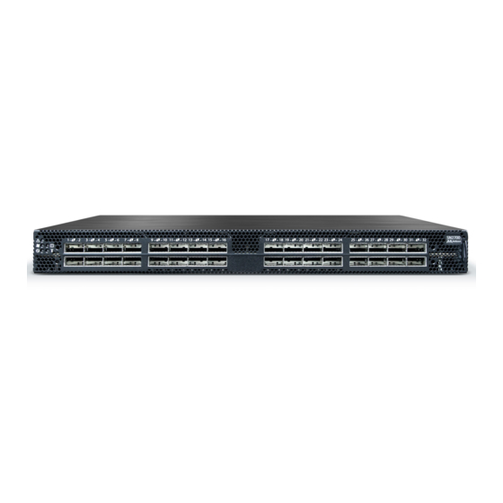
- Page 1 NVIDIA Spectrum SN2000 1U Switch Systems Hardware User Manual 10/25/40/50/100GbE Open Ethernet Switch Systems Models: SN2700, SN2740, SN2410, SN2201, SN2100, SN2010 Exported on Sep/19/2022 02:25 PM...
-
Page 2: Table Of Contents
SN2201 Tool-Less Rail Kit ................. 38 Tool-Less 4-Post Mounting Rail-Kit............38 Tool-Less 2-Post Mounting Rail-Kit............42 Cable Installation .................. 44 Splitter (Breakout) Cables and Adapters ........... 46 Initial Power On ..................49 System Bring-Up..................50 Configuring Network Attributes Using NVIDIA Onyx (MLNX-OS) ......50... - Page 3 Bad Port LED ..................65 Port LEDs ..................66 Inventory Information ................68 Software Management ...............71 Upgrading Software................71 NVIDIA Onyx (MLNX-OS) Software Upgrade..........71 Switch Firmware Update..............71 Cumulus Linux Software Upgrade ............71 Troubleshooting ................72 Specifications..................74 SN2700 Series..................74 SN2740 Series (End of Life)...............
- Page 4 Appendixes..................80 Accessory and Replacement Parts ............... 80 Thermal Threshold Definitions..............81 Interface Specifications................82 QSFP28 Pin Description ............... 82 SFP28 Pin Description ................. 84 RJ-45 CONSOLE and I²C Interface ............85 RJ45 to DB9 Harness Pinout ..............86 RJ45 to RJ45 Harness................86 Disassembly and Disposal .................
- Page 5 Relevant for Models: SN2700, SN2740, SN2410, SN2100, SN2010 and SN2201. About this Manual This manual describes the installation and basic use of NVIDIA Ethernet switches based on the NVIDIA Spectrum IC device. Ordering Information See Introduction. Intended Audience This manual is intended for IT managers and system administrators.
-
Page 6: Ordering Information
920-9N101-00F7- standard depth, P2C airflow, Rail Kit MSN2700-CS2F NVIDIA Spectrum based 100GbE, 1U Open Ethernet Switch with NVIDIA Onyx (MLNX-OS), 32 QSFP28 ports, 2 Power Supplies (AC), x86 920-9N101-00F7- CPU, Standard depth, P2C airflow, Rail Kit, RoHS6 MSN2700-CS2FC NVIDIA Spectrum 100GbE 1U switch w/Cumulus Linux, 32 QSFP28... -
Page 7: Sn2410 Ordering Part Numbers
Short depth, P2C airflow, Rail Kit, RoHS6 MSN2410-BB2R NVIDIA Spectrum based 10GbE/100GbE 1U Open Ethernet switch with 920-9N112-00R7- NVIDIA Onyx (MLNX-OS), 48 SFP28 ports, 8 QSFP28 ports, 2 power supplies (AC), x86 dual core, Short depth, C2P airflow, Rail Kit, RoHS6 MSN2410-BB2RO... -
Page 8: Sn2100 Ordering Part Numbers
Rail Kit must be purchased separately MSN2100-CB2F NVIDIA Spectrum based 100GbE, 1U Open Ethernet Switch with 920-9N100-00F7-0 NVIDIA Onyx (MLNX-OS), 16 QSFP28 ports, 2 AC PSUs, x86 2-core, short depth, P2C airflow, Rail Kit must be purchased separately, RoHS6 MSN2100-CB2FC NVIDIA Spectrum 100GbE 1U switch w/Cumulus Linux, 16 QSFP28... -
Page 9: Sn2010 Ordering Part Numbers
Legacy Part Marketing Description Number MSN2010-CB2F NVIDIA Spectrum-based 25GbE/100GbE, 1U Open Ethernet Switch with NVIDIA Onyx, 18 SFP28 and 4 QSFP28 ports, 2 Power Supplies (AC), 920-9N110-00F7-0 short depth, x86 quad core, P2C airflow, Rail Kit must be purchased separately MSN2010-CB2FC... - Page 10 Part Number Legacy Part Marketing Description Number MSN2201-CB2RO Nvidia Spectrum based 1GBase-T/100GbE 1U Open Ethernet switch with ONIE, 48 RJ45 ports and 4 QSFP28 ports, Dual Power Supply (AC), 920-9N110-00R1-0 x86 CPU, short depth, C2P airflow, 4-post Rail kit.
-
Page 11: Introduction
While NVIDIA Spectrum provides the thrust and acceleration that powers the switch systems, they get yet another angle of capabilities, running with a powerful x86-based processor, which allows them to not only be the highest performing switch fabric elements, but also grants them the ability to incorporate a Linux running server into the same device. - Page 12 SN2700 SN2740 SN2410 SN2100 SN2010 Rear View...
-
Page 13: Speed And Switching Capabilities
SN2700 and SN2410 SN2740 SN2100 SN2010 SN2201 SN2201 Speed and Switching Capabilities The table below describes maximum throughput and interface speed per system model. -
Page 14: Management Interfaces, Psus And Fans
System 1GbT RJ45 1/10/25GbE SFP28 40/50/100GbE QSFP28 Model Interfaces Interfaces* Interfaces* Throughput SN2700 32** 64 32 6.4Tb/s (using QSFP to SFP splitter cables) SN2740 32** 64 32 6.4Tb/s (using QSFP to SFP splitter cables) SN2410 48*+8** Total 64, 48SFP+16 4Tb/s (using QSFP to SFP splitter cables) ... -
Page 15: Features
In the main menu, click on Products > Ethernet Switch Systems, and select the desired product page. Certifications The list of certifications (such as EMC, Safety and others) per system for different regions of the world is located on the NVIDIA website at http://www.mellanox.com/page/ environmental_compliance. -
Page 16: Installation
Unless otherwise specified, NVIDIA products are designed to work in an environmentally controlled data center with low levels of gaseous and dust (particulate) contamination. The operation environment should meet severity level G1 as per ISA 71.04 for gaseous contamination and ISO 14644-1 class 8 for cleanliness level. -
Page 17: Air Flow
Air Flow • The following information does not apply to SN2100/SN2010. In the SN2100/SN2010 systems, the fan units are non-replaceable. • The drawings are provided for illustration purposes only. The panel and modules design may vary depending on the system. The systems are offered with two air flow patterns: •... -
Page 18: Package Contents
Direction Description and OPN Designation Connector side inlet to power side outlet. The airflow direction is indicated by red latches or by red dots that are placed on the power inlet side. OPN designation is “-R”. Power side inlet to connector side outlet. The airflow direction is indicated by blue latches or by blue dots that are placed on the power inlet side. -
Page 19: System Mounting Options
If anything is damaged or missing, contact your sales representative at support@mellanox.com. System Mounting Options The systems are shipped with the rail-kits specified in the following table: System Model Rail Kit SN2700 SN2700 Static Rail Kit Optional: SN2700 Telescopic Rail Kit SN2410, SN2740 SN2740/SN2410 Static Rail Kit SN2100, SN2010 ... - Page 20 Prerequisites: Before mounting the system to the rack, select the way you wish to place the system. Pay attention to the airflow within the rack cooling, connector and cabling options. While planning how to place the system, consider the two installation options shown in the figure below, and review the following points: •...
- Page 21 To mount the system into the rack: At least two people are required to safely mount the system in the rack. Attach the left and right rack mount rails (A) to the switch, by gently pushing the switch chassis’ pins through the slider key holes, until locking occurs. Secure the chassis in the rails by screwing 2 flat head Phillips screws (E) in the designated points with a torque of 1.5±0.2 Nm. ...
- Page 22 Attaching the Rails to the Chassis Attach the left and right rack mount brackets (B) to the switch, by gently pushing the switch chassis’ pins through the slider key holes, until locking occurs. Secure the system in the brackets by screwing the remaining 2 flat head Phillips screws (E) in the designated points with a torque of 1.5±0.2 Nm. ...
-
Page 23: Removing The System From The Rack
While your installation partner is supporting the system’s weight, perform the following steps: Mount the system into the rack enclosure, and attach the brackets installed on the system to the rack’s posts. Secure the brackets to the rack’s posts by inserting four M6 screws in the designated cage nuts, as described in the figure below. -
Page 24: Sn2700 Telescopic Rail Kit
SN2700 Telescopic Rail Kit The telescopic rail kit is not included in the system’s package, and can be purchased separately. There are two installation kit options: • Standard depth systems should be mounted using the standard rail kit. • Short depth systems can be mounted using either of the rail kits. - Page 25 Prerequisites The rails must be separated prior to the installation procedure. To separate the rails: Extend the rail assembly by pulling the extension outwards (D). Extract rail A from rail C by pushing it outside from the rear part of the assembly. To allow complete separation of rail A from rail C, press the quick-release latch.
- Page 26 • In case there are cables that cannot bend within the rack, or in case more space is needed for cable bending radius, it is possible to recess the connector side or the FRU side by 3” or 4” (7.62 or 10.16cm) by optional placement of the system’s rails. •...
-
Page 27: Removing The System From The Rack
Secure the chassis in the inner rails by screwing the 2 flat head Phillips screws (F) in the designated points with a torque of 1.5±0.2 Nm. Securing the Chassis in the Inner Rails Slide the switch into the rack by carefully pushing the inner rails into the outer rails installed on the rack. ... -
Page 28: Sn2740/Sn2410 Static Rail Kit
Pulling the Unit Outwards Press on the locking spring (appears in red in the figure below) on both sides simultaneously, and continue pulling the unit towards you until it is fully removed. Locking Mechanism SN2740/SN2410 Static Rail Kit By default, the system is sold with the standard-depth rail kit. The short-depth rail kit can be supplied upon request. - Page 29 Prerequisites Before mounting the system to the rack, select the way you wish to place the system. Pay attention to the airflow within the rack cooling, connector and cabling options. While planning how to place the system, consider the two installation options shown in the Installation Options figure below, and review the following points: •...
- Page 30 To mount the system into the rack: At least two people are required to safely mount the system in the rack. Attach the left and right rack mount rails (A) to the switch, and secure the chassis in the rails by screwing 2 flat head Phillips screws (D) in the designated points on each side (a total of 4 screws).
-
Page 31: Sn2100/Sn2010 Side By Side Mounting Rail Kit
While your installation partner is supporting the system’s weight, perform steps 3, 4 and 5: On the rear side of the cabinet, install the two blades (B) in the selected rack unit, using four M6 screws (C). Do not tighten the screws yet. Attaching the Rails to the Rack Slide the two blades into the left and right rails, and adjust them to fit your rack's depth. - Page 32 Kit Part Rack Size and Rack Depth Range Number Legacy Part Numbe 930-9NRKT-00 MTEF- Rack installation kit for SN2100/SN2010 series short depth 1U switches, allows JG-000 KIT-D installation of one or two switches side-by-side into standard depth racks. The following parts are included in the rail kit (see figure below): •...
- Page 33 • You may choose to install your system in the right or in the left part of the metal frame. The following instructions apply to installation in the right part. For installation in the frame’s left part, follow the same instructions, while replacing “right” with “left”, and vice versa. To mount the system into the rack: ...
- Page 34 In the next step you will be attaching the mounting rails to the switch sides. Before doing that, make sure the cables are laid properly within them. Avoid using excessive pressure, as it can damage the cables. While holding the cables stably together in the blade’s rail with one hand, use your other hand to secure the blades to the chassis.
- Page 35 Step 6. Install ten cage nuts in the desired slots of the rack: three cage nuts in the front part of each cabinet post, and two cage nuts in the rear part of each cabinet post. Installing the Cage Nuts Attach the frame to the rack by using ten spacer cage nuts, and screw ten M6 pan head screws - four in the front part of the rack, and 6 in its rear part.
-
Page 36: Sn2100/Sn2010 Static Single Switch Rail Kit
Do not remove both of the blank covers at the same time. When no system is installed, at least one of them should be present to support the frame’s partition. Remove the blank cover from the selected slot in the frame, and mount the system by sliding its mounting blades into the frame. - Page 37 • 8 M6 spring washers (D) • 8 M6 flat washers (E) • 2 rack mount blades (F) • 2 system brackets (G) Rack Rail Kit Parts To mount the system into the rack: At least two people are required to safely mount the system in the rack. Attach the 2 system rails to the system’s sides using 8 flat head 4-40 screws (A) in each side.
-
Page 38: Sn2201 Tool-Less Rail Kit
Tool-Less 4-Post Mounting Rail-Kit Kit Part Number Kit Legacy Part Number Rack Size and Rack Depth Range 930-9NRKT-00JS-000 MTEF-KIT-M-TL NVIDIA Tool-less rack installation kit, 4-post rack, for SN2201 switch The following parts are included in the tool-less rail kit (see figure below):... - Page 39 • 2x Rack mount rails (A) • 2x Rack mount blades (B) • 2x Inner rails (C) Rail-Kit Parts 2xA 2xB 2xC Prerequisites: •...
- Page 40 Attach the switch to the left and right inner rails according to your installation selection - • Standard Installation: The inner rails should be assembled to the switch using the first five holes (from its front side). • Recessed Installation: The inner rails should be assembled to the switch skipping the first hole (from its front side).
- Page 41 Install the outer rails (B+C) in the rack, as shown in the following illustration: Mount the chassis onto the rack: Insert the chassis into the middle-outer rails installed in the rack (C). Secure the chassis in place by tightening the thumb-screws.
-
Page 42: Tool-Less 2-Post Mounting Rail-Kit
Legacy Kit Part Number Rack Size and Rack Depth Range 930-9NRKT-00JR-000 MTEF-KIT-M NVIDIA fixed installation kit, 2-post rack, for SN2201 switch The following parts are included in the 2-post mounting rail kit (see figure below): • 2x Rack mount brackets (A) ... - Page 43 2xA 12xB 4xC 4xD Attach the two brackets (A) to the chassis, using the 12 M4 screws (B) provided in the kit. Install 4 cage nuts (C) in the desired 1U slots of the rack.
-
Page 44: Cable Installation
To remove a cable, disengage the locks and slowly pull the connector away from the port receptacle. The LED indicator for that port will turn off when the cable is unseated. For full cabling guidelines, ask your NVIDIA representative for a copy of NVIDIA Cable Management Guidelines and FAQs Application Note. - Page 45 For more information about port LEDs, refer to Port LEDs. Do not force the cable into the cage with more than 40 newtons/9.0 pounds/4kg force. Greater insertion force may cause damage to the cable or to the cage. QSFP Cable Orientation SN2010 SFP Cable Orientation SN2740 Cable Orientation...
-
Page 46: Splitter (Breakout) Cables And Adapters
SFP28 ports; see "SN2410 Splitting Options" below. Splitter (Breakout) Cables and Adapters A 100GbE port can be split to two 50GbE ports, or to four (or less) 25GbE ports, using an NVIDIA splitter cable. Splitting a 100GbE QSFP28 port to 4 separate 25GbE ports (using a splitter cable) may disable (unmap) the 100GbE port below it. - Page 47 systemctl restart switchd command. For more details, see Layer 1 and Switch Port Attributes in the Cumulus Linux User Guide. Examples of Splitter (Breakout or Fanout) Cables SN2700 and SN2740 Splitting Options The top QSFP28 ports marked in green are splittable to 4 SFP28 ports, each. The bottom QSFP28 ports (gray) are blocked when the upper ports are in split mode.
- Page 48 SN2100 Splitting Options All QSFP28 ports are splittable. Each port can be split into 4xSFP28 (10/25G) or 2xQSFP28 (50G) ports. There are no blocking requirements. SN2010 Splitting Options All QSFP28 ports are splittable. Each port can be split into 4xSFP28 (10/25G) or 2xQSFP28 (50G) ports.
-
Page 49: Initial Power On
It may take up to five minutes to turn on the system. If the System Status LED shows amber after five minutes, unplug the system and call your NVIDIA representative for assistance. Check the System Status LEDs and confirm that all of the LEDs show status lights consistent with normal operation (initially flashing, and then moving to a steady color) as shown in the figures below. -
Page 50: System Bring-Up
Stabilise’e”. Pour isoler completement le module en cause, Il faut de’brancher toutes les alimentations stabilise’es. System Bring-Up For bring-up of a switch system with NVIDIA Onyx (MLNX-OS) operating system installed, see Configuring Network Attributes Using NVIDIA Onyx (MLNX-OS). For bring-up of a switch system with Cumulus Linux operating system installed, see Configuring... - Page 51 Flow Control None Step 3. Login as admin and use admin as password. On the first login, the NVIDIA Onyx (MLNX-OS) configuration wizard will start. Step 4. To configure network attributes and other initial parameters to the system, follow the configuration wizard as shown in the Configuration Wizard Session table below.
- Page 52 Comments Wizard Session Display You have entered the following information: The wizard displays a summary of your choices and <A summary of the configuration is now then asks you to confirm the choices or to re-edit displayed.> them. To change an answer, enter the step number to Either press <Enter>...
- Page 53 (config) # Step 6. Check the software version embedded in your system, using the command ‘show version’. Compare this version to the latest version that can be retrieved from NVIDIA support site. To upgrade software, please refer to the NVIDIA Onyx (MLNX-OS) User Manual.
-
Page 54: Configuring Network Attributes Using Cumulus Linux
Power Supply NVIDIA systems that are equipped with two replaceable power supply units work in a redundant configuration. Either unit may be extracted without bringing down the system. -
Page 55: Fans
The power supply slots of SN2740 and SN2410 should not be left empty for more than 5 minutes. Remove the power cord from the power supply unit. Grasping the handle with your hand, push the latch release with your thumb while pulling the handle outward. - Page 56 Grasping the handle with your right hand, push the latch release (if exists) with your thumb, while pulling the handle outward. As the fan unit unseats, the fan unit status LEDs will turn off. Remove the fan unit. To insert a fan unit: Make sure the mating connector of the new unit is free of any dirt and/or obstacles.
-
Page 57: Interfaces
Notes: a. 4.5W high power modules are supported on NVIDIA Onyx (MLNX-OS) from version 3.6.3004 onwards. b. 5.0W high power modules are supported on NVIDIA Onyx (MLNX-OS) from version 3.x.1xxx onwards for 100GbE Fiber Optics up to 80km. c. SFP28 ports. -
Page 58: Supported Passive Cables In Sn2010Bm
Ethernet speed must be set manually. The system’s ports can be manually configured to run at speeds ranging from 10GbE to 100GbE (for more details, see Specifications). To change the port speed configuration, use the command “speed” under interface configuration mode. Refer to the NVIDIA Onyx (MLNX-OS) User Manual for instructions on port speed re-configuration. -
Page 59: I2C/Rs232 (Console)
The USB interface is USB 2.0 (mini USB in SN2100) compliant (USB 1.0 is not supported) and can be used by NVIDIA Onyx (MLNX-OS) software to connect to an external disk for software upgrade or file management. The connector comes in a standard USB shape. -
Page 60: Reset Button
To reset the system, the CPU of its management board, and the “admin” password, push the reset button and keep it pressed for at least 15 seconds. When using a NVIDIA Onyx (MLNX-OS) based system, this should allow you to enter without a password and set a new password for the user “admin”. -
Page 61: System Status Leds
SN2201 It may take up to five minutes to turn on the system. If the System Status LED shows red after five minutes, unplug the system and call your NVIDIA representative for assistance. System Status LED Assignments LED Behavior Description... -
Page 62: Fan Status Leds
Major error has occurred. For example, If the System Status LED shows red five corrupted firmware, system is minutes after starting the system, unplug overheated etc. the system and call your NVIDIA representative for assistance. Fan Status LEDs LED Type System... -
Page 63: Power Supply Status Leds
Risk of Electric Shock! With the fan module removed, power pins are accessible within the module cavity. Do not insert tools or body parts into the fan module cavity. Power Supply Status LEDs Power Supply Status LEDs LED Type System Front Rear... - Page 64 Description Action Required Solid Green The PSU is running normally. Flashing Green 1Hz Call your NVIDIA representative for AC present / Only 12VSB on (PSU off) or PSU assistance. in Smart-on state. Amber AC cord unplugged or AC power lost while...
-
Page 65: Unit Identification Led
LED Behavior Description Action Required Flashing Amber Power supply warning events where the Call your NVIDIA representative for power supply continues to operate; high assistance. temp, high power, high current, slow fan. No AC power to all power supplies. Call your NVIDIA representative for assistance. -
Page 66: Port Leds
Port LEDs System Port LEDs SN2700 SN2740 SN2410 QSFP28: SFP28: SN2010 QSFP: SFP:... - Page 67 System Port LEDs SN2100 SN2201 RJ45: QSFP28: In the SN2410 systems, the status of each pair of adjacent QSFP28 ports is indicated by four LEDs, as shown in the picture above: • While the bottom LEDs signify the port status in regular condition, the upper LEDs operate only when the port is split.
-
Page 68: Inventory Information
LED Behavior Description Action Required Flashing Amber A problem with the link Check the cable, and replace it if needed. 1GBase-T LEDs in Ethernet System Mode LED Behavior Description Action Required Link is down Check that the near-end and far-end connectors are properly plugged, check cable integrity. - Page 69 SN2410 Inventory Information Illustration SN2100 Pull-out Tab SN2010 Pull-out Tab...
- Page 70 SN2201 Pull-out Tab...
-
Page 71: Software Management
Software and firmware updates are available from the NVIDIA Support website. Check that your current revision is the latest one available on the NVIDIA Support website. If you do not have the latest revision, upgrade your software using the CLI or the GUI. Copy the updated software to a known location on a remote server within the user’s LAN. -
Page 72: Troubleshooting
Problem Indicator Symptoms LEDs System Status LED is blinking for more than 5 minutes Cause: NVIDIA Onyx (MLNX Solution: Connect to the s an FAE if the NVIDIA Onyx System Status LED is red Cause: • Critical system fau •... - Page 73 Problem Indicator Symptoms System date and time reset The date and time settings were reset to the default configuration following an AC power loss Cause: Date and time are reconfi Solution: • To set the system’s # clock set <hh:mm •...
-
Page 74: Specifications
CPU: Intel x86 1.40GHz Dual Core PCIe: 4x Gen2.0 Switch: NVIDIA Spectrum Memory: 8GB DDR3 RAM, 32G SSD for systems based on Switch rev. B1 and earlier 8GB DDR3 RAM, 16G SSD for systems based on Switch rev. B2 and higher Throughput 6.4Tb/s... -
Page 75: Sn2740 Series (End Of Life)
40GbE/100GbE Models - Typical power with passive cables (ATIS): 140.4W (same as the 100GbE models) Main Devices CPU: Intel x86 2.40GHz Quad Core PCIe: 4x Gen2.0 Switch: NVIDIA Spectrum Memory: 8GB DDR3 RAM, 16G SSD Throughput 6.4Tb/s SN2410 Series Feature Value Mechanical Size: ... -
Page 76: Sn2100 Series
CPU: Intel x86 1.40GHz Dual Core PCIe: 4x Gen2.0 Switch: NVIDIA Spectrum Memory: 8GB DDR3 RAM, 32G SSD for systems based on Switch rev. B1 and earlier 8GB DDR3 RAM, 16G SSD for systems based on Switch rev. B2 and higher... -
Page 77: Sn2010 Series
Typical power with passive cables (ATIS): 74W Main Devices CPU: Intel x86 2.40GHz Quad Core PCIe: 4x Gen2.0 Switch: NVIDIA Spectrum Memory: SDRAM: 8GB DDR3L 1600 MT/s SO-DIMM Storage: 16GB Dual Channel MLC M.2-SATA SSD Throughput 3.2Tb/s SN2010 Series Feature... -
Page 78: Sn2201 Series
Typical power with passive cables (ATIS): 66W Main Devices CPU: Intel x86 2.40GHz Quad Core PCIe: 4x Gen2.0 Switch: NVIDIA Spectrum Memory: SDRAM: 8GB DDR3L 1600 MT/s SO-DIMM Storage: 16GB Dual Channel MLC M.2-SATA SSD Throughput 1.7Tb/s SN2201 Series Feature... - Page 79 Feature Value Memory: SDRAM: 8GB ECC DDR4 SO-DIMM Storage: 20GB SSD M.2 PCIe Gen 3 Throughput 448GB/s...
-
Page 80: Appendixes
AC-A (rear to front) SN2740, discontinued. It SN2410 is replaced by MTEF-PSR- AC-I. 930-9BPSU-00J MTEF-PSF- NVIDIA Power-Supply Unit, 550W AC, P2C SN2700, The Network 4-000 AC-I Airflow, For SB7700, SB7800, SB7890, SN2740, operating SN2410, SN2700, SX6710, SN2740, SX1410, SN2410 system identifies... -
Page 81: Thermal Threshold Definitions
Part Number Legacy Part Description Supported Notes Part Systems Number 930-9BPSU-00J MTEF-PSR- NVIDIA Power-Supply Unit, 550W AC, C2P SN2700, L-000 AC-I Airflow, For SB7700, SB7800, SB7890, SN2740, The Network SN2410, SN2700, SX6710, SN2740 ,SX1410, SN2410 operating SX1710 switches, Power cord included... -
Page 82: Interface Specifications
Interface Specifications QSFP28 Pin Description QSFP Pin Description Connector Pin Number Symbol Signal Description Ground Tx2n Connected to Port 2 lane Rx Inverted Data Tx2p Connected to Port 2 lane Rx Non-Inverted Data Ground Tx4n Connected to Port 4 lane Rx Inverted Data Tx4p Connected to Port 4 lane Rx... - Page 83 Connector Pin Number Symbol Signal Description 2-wire serial interface clock 2-wire serial interface data Ground Rx3p Connected to Port 3 lane Tx Non-Inverted Data Rx3n Connected to Port 3 lane Tx Inverted Data Ground Rx1p Connected to Port 1 lane Tx Non-Inverted Data Rx1n Connected to Port 1 lane Tx...
-
Page 84: Sfp28 Pin Description
SFP28 Pin Description Rear View of Module with Pin Placement SFP Pin Description Symbol Name Description Note VeeT Module Transmitter Ground TX_Fault Module Transmitter Fault TX_Disable Transmitter Disable. Turns off transmitter laser output 2-wire Serial Interface Data Line 2-wire Serial Interface Clock Line MOD_ABS Module Absent. -
Page 85: Rj-45 Console And I²C Interface
Symbol Name Description Note VeeR Receiver Ground (Common with Transmitter Ground) VeeR Receiver Ground (Common with Transmitter Ground) Receiver Inverted DATA out. AC Coupled Receiver Non-inverted DATA out. AC Coupled VeeR Receiver Ground (Common with Transmitter Ground) VccR Receiver Power Supply VccT Transmitter Power Supply VeeT... -
Page 86: Rj45 To Db9 Harness Pinout
Signal Pin# Color Bl/W I²C_SDA Br/W Not connected RJ45 to DB9 Harness Pinout The RS232 harness cable (DB9 to RJ45) is provided within the package to connect a host PC to the system's Console RJ45 port. RJ45 to DB9 Harness Pinout ... -
Page 87: Disassembly And Disposal
Disassembly and Disposal Disassembly Procedure To disassemble the system from the rack: Unplug and remove all connectors. Unplug all power cords. Remove the ground wire. Unscrew the center bolts from the side of the system with the bracket. Support the weight of the system when you remove the screws so that the system does not fall. -
Page 89: Document Revision History
Document Revision History Date Revision Description July 2022 3.7 Updated OPNs in: • Ordering Information • Installation • Accessory and Replacement Parts Updated Interface Specifications June 2022 Updated: • LED Notifications • Interfaces • Interface Specifications • Maximum altitude updated to 5000m in SN2201 table under Specifications January 27, 2022... - Page 90 Date Revision Description March 2019 Updated: • Interfaces • Management December 2018 Migrated to online format; minor reorganization October 2018 Updated High Power/LR4 Transceivers Support in Interfaces chapter. August 2018 Added Static Single Switch Rail Kit for SN2100/ SN2010 July 2018 Updated “Data Interfaces”...
- Page 91 Date Revision Description March 2016 Added "Taiwan BSMI Class A Statement in Safety Warnings" Updated: • “Introduction to Mellanox SN2000 Spectrum™ Ethernet Switch Systems” • “Software Management” • “Troubleshooting Instructions” • “Specifications” • “Accessory and Replacement Parts” December 2015 Added SN2410 August 2015 First revision...
- Page 92 NVIDIA accepts no liability related to any default, damage, costs, or problem which may be based on or attributable to: (i) the use of the NVIDIA product in any manner that is contrary to this document or (ii) customer product designs.
- Page 93 Copyright © 2022 NVIDIA Corporation & affiliates. All Rights Reserved.
Need help?
Do you have a question about the Spectrum SN2000 and is the answer not in the manual?
Questions and answers