Jolly Mec AERJOLLY 80 EVO 15 Instructions For Installation, Use And Maintenance Manual
Hide thumbs
Also See for AERJOLLY 80 EVO 15:

Related Manuals for Jolly Mec AERJOLLY 80 EVO 15


Summary of Contents for Jolly Mec AERJOLLY 80 EVO 15
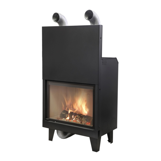
- Page 1 AERJOLLY 80 EVO 15 AERJOLLY 80 EVO 15 CT I N S T A L L A T I O N , U S E A N D MAINTENANCE MANUAL To be kept by the purchaser AERJOLLY 80 EVO Wood burning air fireplace...
- Page 2 Dear Customer, thank you for having chosen to heat and save with a Jolly Mec product. Please carefully read and keep this sheet before using the equipment. This sheet provides necessary information and suggestions on how to correctly install, use, clean and maintain the product.
-
Page 3: Table Of Contents
TABLE OF CONTENTS CHAP.01 PREMISES........................... 4 01.1 WARNINGS ..............................4 01.2 SYMBOLOGY ............................... 5 01.3 APPLIED STANDARDS ..........................5 01.4 USE AND STORING OF THE INSTALLATION AND MAINTENANCE MANUAL ........6 01.5 MANUFACTURER’S LIABILITY AND WARRANTY CONDITIONS ............. 6 CHAP.02 ACCIDENT PREVENTION / SAFETY REGULATIONS .............. 7 02.1 GENERAL CONSIDERATIONS ........................ -
Page 4: Chap.01 Premises
CHAP.01 PREMISES 01.1 WARNINGS • Familiarity and compliance with the instructions given in this manual will ensure quick installation and correct use of the appliance. • Read the manual attentively before commencing installation, and be certain to follow the directions it contains, otherwise the war- ranty could be invalidated and the performance and safety of the appliance jeopardized. • The installation manual is an integral part of the product and must be given to the user. • It must be kept in a safe place and consulted carefully, as all of the warnings provide important information on safety during instal- lation, use and maintenance. • Incorrect installation of the appliance could cause damage and injury to people or animals, for which the manufacture cannot not be held liable. • Installation shall be performed by qualified operators in accordance with the regulations in force in the Country of installation. • The manufacturer declines any contractual or non-contractual liability for damages caused by errors in installation or use of the appliance or failure to follow the instructions contained in this manual. • All rights on the reproduction of this technical manual are owned by Jolly Mec Caminetti S.p.A. The descriptions and illustrations provided in the following publication are not binding. • reserves the right to make any modifications that may be deemed appropriate. • Jolly Mec Caminetti S.p.A This manual cannot be given to third parties for perusal without the written permission of • Jolly Mec Caminetti S.p.A • The technical directions for installation contained in this manual should be considered as basic requirements. Regulations in some countries may be more restrictive; in this instance, comply fully with the regulations prevailing in the country of installation (all laws and local bylaws must be observed when installing and using the appliance, including those referring to national and European standards). -
Page 5: Symbology
This point is particularly important. An important point regarding behaviour for preventing injury and damage to DANGER: materials is expressed. 01.3 APPLIED STANDARDS All JOLLY MEC products are constructed according to the following directives: European construction products regulation. • EU 305/2011 Machines. •... -
Page 6: Use And Storing Of The Installation And Maintenance Manual
01.5 MANUFACTURER’S LIABILITY AND WARRANTY CONDITIONS Upon the delivery of this manual, Jolly Mec S.p.A. cannot be held liable, whether civil or criminal, for accidents due to partial or total non-compliance with the specifications herein contained. The manufacturer is especially held harmless from any liability in the following cases: •... -
Page 7: Chap.02 Accident Prevention / Safety Regulations
CHAP.02 ACCIDENT PREVENTION / SAFETY REGULATIONS 02.1 GENERAL CONSIDERATIONS • The manual refers to essential aspects of the directives, regulations and dispositions on using the machine, summarising its most significant points. • General legal regulations and mandatory rules regarding injury prevention and environmental protection must be observed. -
Page 8: Safety Regulations For Extraordinary Maintenance And Installation
• Keep the ventilation grids in the area the appliance is installed in clean conditions. • Do not use fuels that are not recommended. • Check and periodically clean the fume exhaust pipe, from the appliance to the flue (Union). •... -
Page 9: Equipment For Operators And Maintenance Personnel
RESIDUAL RISKS Though JOLLY MEC CAMINETTI S.p.A. does everything within its power to produce its systems with the greatest competence regarding safety and consulting all the directives, laws, and regulations available, there are still, if minor, some residual risks during the phases of: •... -
Page 10: Chap.03 Handling And Transport
CHAP.03 HANDLING AND TRANSPORT 03.1 RECEIVING GOODS The device is delivered on a pallet in a cardboard box and protected with shrink wrap cover sheet when receiving merchandise, check that: • all packaging is intact • all of the merchandise indicated on the delivery bill has actually been delivered •... -
Page 11: Chap.04 Ecological Regulations
CHAP.04 ECOLOGICAL REGULATIONS 04.1 WASTE MATERIALS AND THEIR DISPOSAL Spare parts replaced during the machine’s product life are to be considered waste and must be taken to special collection centres or entrusted to authorised disposal centres. Ashes must be placed in a metal container with a sealed lid. The closed container must be placed on a non-combustible base and kept away from combustible materials until all the embers have been extinguished. - Page 12 END-OF-LIFE DISPOSAL OF THE EQUIPMENT COMPONENTS ( REGULATION (EU) 2015/1185 - Annex II - par. 3 - a) - 3) ) INSTRUCTIONS FOR CORRECT PRODUCT DISPOSAL The owner is fully and exclusively liable for stove demolition and disposal according to laws in force in his/her country regarding safety, respect and protection of the environment. At the end of its useful life, the product must not be disposed of together with urban waste. It can be delivered to the appropriate differentiated collection centres set up by the municipal administrations, or to retailers that provide this service.
-
Page 13: Cap.05 Description
The fireplaces AERJOLLY 80 EVO 15 and AERJOLLY 80 EVO 15 CT are monoblock wood burning with intermittent kind of combustible charging modality;insert devices approved to EN13229 Standard requirements. -
Page 14: Product Identification
05.2 PRODUCT IDENTIFICATION It is COMPULSORY to indicate the product MODEL, the LOT number and SERIAL NUMBER in all communications with the Manufacturer. Identification numbers are printed on the adhesive plate located on the back of the appliance as illustrated. Appliance performance values measured during inspection tests according to the indicated reference and EC markings are also included on the plate. -
Page 15: Cap.06 Technical Data
All appliance tests, final inspection and fine-tuning was performed using the recommended fuels. Jolly Mec Caminetti S.p.A. is not responsible for malfunctions, breakdowns or problems due to the use of wood logs that are not recommended, as combustion parameters vary according to the quality of the fuel. -
Page 16: Recommended Fuels
06.2 RECOMMENDED FUELS WARNING WOOD QUALITY IS VERY IMPORTANT; PLEASE READ THIS SECTION CAREFULLY. The characteristics of fuel wood for stoves and fireplaces are defined by quality classes A1 and A2 set forth by UNI EN ISO 17225-5 standard. WOOD COMBUSTION Wood clean burning is a process that reflects the natural decomposition itself;... -
Page 17: Components
06.3 COMPONENTS The equipment is supplied on a pallet, with heat shrink film and with the following additional components: • Installation, use and maintenance manual • Heat proof glove • Extensible aluminium pipe for combustion air canalisation (2) and related hose clamp (3); •... -
Page 18: Dimensions
06.4 DIMENSIONS All measurements are in mm. ● Aerjolly 80 EVO 15 Heating fan (optional) Comburent air intake Ø120 mm Smoke exhaust Hot air outlet for natural convection Hot air outlet of the heating fan ● Aerjolly 80 EVO 15 CT Heating fan (optional) Comburent air intake Ø120 mm Smoke exhaust Hot air outlet for natural convection Hot air outlet of the heating fan... -
Page 19: Chap.07 Positioning And Connections For The Installer
CHAP.07 POSITIONING AND CONNECTIONS FOR THE INSTALLER 07.1 FLUE OR FUME EXHAUST SYSTEM The flue or fume exhaust system is a fundamental element for the proper functioning of the stove and must comply with the following general standards: EN1856-1 Chimneys. Requirements for metal chimneys - Part 1: System chimney products EN1856-2 Chimneys. -
Page 20: Installation Room Ventilation
The use of counter slope elements is forbidden.The flue union must have a constant section and allow soot to be collected and swept away. Changes in cross-section are only allowed at the outlet of the heat generator: the use of adaptors on the coupling with the chimney flue is prohibited. -
Page 21: Assembly Sequence
07.3 ASSEMBLY SEQUENCE The fireplace travels on pallet. To facilitate assembly and transport open the fireplace and remove the various components.(Fig. 2-3); To unlock the combustion chamber door, unscrew and remove the screw M8, as shown in the Fig. 1, on the sides of the fireplace After preparing the electrical connections and the air inlets depending on the configuration type (see chap. - Page 22 Proper position b) Fan assembly 1- Open the combustion chamber door. Remove the cast iron bottom grate (1) and the ash basket (2) (Fig. 1-2); 2 - Remove the fire bed central panels (3) (Fig. 3). 3 - Unscrew the 4 screws (4) to remove the closing metal sheet (5) of the fireplace base to access the fan supporting box (6) (Fig. 4-5). 4 - Connect the electrical cable to the fan (see chap.
- Page 23 Proper position c) Feet adjustment To adjust the feet height use the 14 mm key. Screw clockwise or anticlockwise the nut 1 to lift or lower the foot.
- Page 24 d) Assembly of combustion chamber panels and deflector Front right and left panel (x2) Side panel (x4) Front central panel (x1) Deflector (x1) 1- Insert the side panel (A) in the left side and towards the fireplace door. Side panel (A) must be positioned in the combustion chamber with the shaped part (a) pointing downwards. Tilt the panel in order to insert it into the combustion chamber (Fig.
- Page 25 2- Insert the side panel (A) in the right side and towards the fireplace door. Side panel (A) must be positioned in the combustion chamber with the shaped part (a) pointing downwards. Tilt the panel in order to insert it into the combustion chamber (Fig. 4). Once inside the combustion chamber, it is possible to position it vertically, to push it against the wall and in its front seat towards the fireplace door (Fig.
- Page 26 4- Insert the left rear panel (C) on the central rear panel left side. The left rear panel (A) must be positioned in the combustion chamber with the non-shaped part (a) pointing downwards and towards the fireplace left wall. Tilt the panel in order to insert it into the combustion chamber (Fig. 10). Once inside the combustion chamber, it is possible to position it vertically, to push it against the fireplace wall and into its seat (Fig.
- Page 27 6- Insert the side panel (A) in the left side and towards the side panel already positioned. Side panel (A) must be positioned in the combustion chamber with the shaped part (a) pointing downwards. Tilt the panel in order to insert it into the combustion chamber (Fig. 16). Once inside the combustion chamber, it is possible to position it vertically, to push it against the wall and into its seat (Fig.17-18).
- Page 28 8- Insert the deflector (D). Deflector (D) must be positioned in the combustion chamber with the sheet metal part (a) pointing upwards. Tilt the deflector in order to insert it into the combustion chamber (Fig. 22). Once inside the combustion chamber, take it up to the fireplace rear wall and turn it in vertical position to lift it and lean it on its front support (b) and rear support of the central rear panels (c) (Fig.23-24).
-
Page 29: Installation Configurations
07.4 INSTALLATION CONFIGURATIONS Install the fireplace as follows: Images shown are for illustration purposes only. 1) Forced air version with fan a) Configuration with fireplace comburent air inlet communicating with the outside, with fan hot air outlets canalised and natural convection hot air outlets not connected. The fireplace can function by taking the comburent air from the outside, connecting it with the extensible aluminium pipe (Ø120 mm and maximum length 100 cm) with the outside (1). In this configuration, the fireplace comburent air inlet connection with the outside environment is mandatory. - Page 30 b) Configuration with fireplace comburent air inlet communicating with the installation room, with fan hot air outlets connected to the coating nozzles and natural convection hot air outlets not connected. The fireplace can function by taking the comburent air from the installation room, connecting it with the extensible aluminium pipe (Ø120 mm and maximum length 100 cm) to the coating (1). In this configuration it is mandatory to make an opening in the installation room (minimum Ø200 mm) (2), communicating with the outside environment, guaranteeing a proper intake of comburent air such that it does not depressurise the installation room.
- Page 31 2) Radiation version without fan a) Configuration with fireplace comburent air inlet communicating with the outside, with hot air outlets not connected. The fireplace can function by taking the comburent air from the outside, connecting it with the extensible aluminium pipe (Ø120 mm and maximum length 100 cm) with the outside (1). In this configuration, the fireplace comburent air inlet connection with the outside is mandatory. Make an opening (minimum 600 cm ) in the coating top part (2) to allow the exit of hot air (of the corresponding outlets on the fireplace (3)) and an opening (minimum 600 cm ) in the coating lower part (4) for heating air intake from the installation room.
- Page 32 b) Configuration with fireplace comburent air inlet communicating with the installation room, with fan hot air outlets and natural convection outlets not connected. The fireplace can function by taking the comburent air from the installation room, connecting it with the extensible aluminium pipe (Ø120 mm and maximum length 100 cm) to the coating (1). In this configuration it is mandatory to make an opening in the installation room (minimum Ø200 mm) (2), communicating with the outside, guaranteeing a proper intake of comburent air such that it does not depressurise the installation room.
-
Page 33: Installing The Cladding: Precautions
07.5 INSTALLING THE CLADDING: PRECAUTIONS • Protection of domestic walls The fireplace must be installed near the non-flammable walls. Installation of the fireplace near inflammable walls is only allowed if you maintain the distances indicated below, or if suitable protection is interposed. The surfaces such as the flooring, ceiling and walls of the home in the vicinity of the fireplace must be protected to prevent overheating. - Page 34 MINIMAL SECTION SIZES FOR CONVECTION AIR INLETS AND OUTLETS In Fig. 3 are shown the minimal section sizes suitable for convection air Inlets and Outlets and applicable to all installation types available: A Min. Convection Air Inlet: 600 cm B Min. Convection Air Outlet: 600 cm C Forced convection air outlet Ø: 2xØ120 m m...
-
Page 35: Example Of Hot Air Canalisation (For Forced Air Version Only)
07.6 EXAMPLE OF HOT AIR CANALISATION (for forced air version only) To duct the air into other rooms, assembly the “T” or “Y” connection (optional), in addiction to connect the grilles on the lining. The air pipes must be routed to the rooms to be heated. The return of air in the fireplace room must be guaranteed from every room in which the hot air arrives, through openings under the doors or vents (see Fig. 1-2). -
Page 36: Control Unit Electrical Wiring Diagram (For Forced Air Version Only)
Prima di fare qualsiasi operazione, assicurarsi che la Tensione di Rete Installare il prodotto solo in ambienti asciutti e in condizioni climatiche corrette Inserire a nonte dell’impianto un interruttore bipolare conforme alle norme vigenti Evitare di accoppiare i cavi delle sonde con quelli di potenza 07.7 CONTROL UNIT ELECTRICAL WIRING DIAGRAM (for forced air version only) ... -
Page 37: Chap.08 Use And Maintenance For The User
(Fig. 3); 3 identical logs for a total of 3,23 kg Position in the middle of the adjustment 49 minutes AERJOLLY 80 EVO 15 CT (Fig. 3); (Fig. 5) ; slot Max length 30-35 cm and width approx. 8-10 cm per side (use of pieces of chopped wood is recommended) Fig. 3... - Page 38 When starting the fireplace again in the future, follow the same procedure illustrated above, cleaning the fireplace beforehand removing excessive ashes from the fire base (bearing in mind that the presence of a layer of ashes on the same makes starting the fire easier). COMBURENT AIR ADJUSTMENT RECORD MAX position: comburent air intake open (Fig.
-
Page 39: Tips For The User
08.2 TIPS FOR THE USER • When the heating system is ducted, it is mandatory to leave at least one vent open to discharge the heat generated when the device is on. • The door must remain closed during wood combustion; it can only be opened to add more wood. •... -
Page 40: Routine Maintenance
Time between one cleaning and the next is strictly tied to fuel quality. The most suitable cleaning frequency can only be established a few days after use according to the actual amount of deposited residue and may vary from recommended Jolly Mec intervals. -
Page 41: Extraordinary Maintenance
08.4 EXTRAORDINARY MAINTENANCE We wish to remind you that the Extraordinary Maintenance to be carried out on this type of product must be done obligatorily every year by qualified maintenance personnel, in order to maintain its functionality, efficiency and comfort. For any further queries you may have, we invite you to contact the specialised Technical Service Center through your retailer. -
Page 42: Chap.09 Fault Diagnosis And Troubleshooting
CHAP.09 FAULT DIAGNOSIS AND TROUBLESHOOTING 09.1 PROBLEMS WARNING In accordance with the laws in force on safety for electrical appliances, a specialised Technical Service Center or qualified personnel must obligatorily be contacted for all installation, maintenance or interventions that require access to electrical parts. -
Page 43: Chap.10 Annexes
Information requirements for solid fuel local space heaters ACCORDING TO COMMISSION REGULATION (EU) 2015/1185 Manufacturer JOLLY-MEC CAMINETTI SPA Trademark JOLLY MEC Model identifier(s) Aerjolly 80 EVO 15 Indirect heating functionality Direct heat output 14,8 Indirect heat output Reference standard EN13229 Notified Body TÜV Rheinland Energy GmBH - NB 2456 - Am Grauen... - Page 44 Type of heat output/room temperature Auxiliary electricity consumption control (select one) Item Symbol Value Unit Item Value 0,000 Single stage heat output, no room At nominal heat output temperature control 0,000 Two or more manual stages, no At minimum heat room temperature control output 0,000...
- Page 45 Information requirements for solid fuel local space heaters ACCORDING TO COMMISSION REGULATION (EU) 2015/1185 Manufacturer JOLLY-MEC CAMINETTI SPA Trademark JOLLY MEC Model identifier(s) Aerjolly 80 EVO 15 CT Indirect heating functionality Direct heat output 14,9 Indirect heat output Reference standard EN13229 Notified Body TÜV Rheinland Energy GmBH - NB 2456 - Am Grauen...
- Page 46 Type of heat output/room temperature Auxiliary electricity consumption control (select one) Item Symbol Value Unit Item Value 0,000 Single stage heat output, no room At nominal heat output temperature control 0,000 Two or more manual stages, no At minimum heat room temperature control output 0,000...
- Page 47 NOTES...
- Page 48 Via S.Giuseppe 2 - 24060 Telgate (Bg) Italy Tel. +39 035.83.59.211 Fax +39 035.83.59.203 www.jolly-mec.it - info@jolly-mec.it...
Need help?
Do you have a question about the AERJOLLY 80 EVO 15 and is the answer not in the manual?
Questions and answers