
Related Manuals for Jolly Mec JOLLY SYNTHESIS 68-80


Summary of Contents for Jolly Mec JOLLY SYNTHESIS 68-80
- Page 1 10 kW and 14 kW I N S T A L L A T I O N , U S E A N D MAINTENANCE MANUAL To be kept by the purchaser JOLLY SYNTHESIS 68-80 JOLLY STAR 68-80 Pellet operated air heating fireplace...
- Page 2 Dear Customer, thank you for having chosen to heat and save with a Jolly Mec product. Please carefully read and keep this sheet before using the equipment. This sheet provides necessary information and suggestions on how to correctly install, use, clean and maintain the product.
-
Page 3: Table Of Contents
TABLE OF CONTENTS CHAP.01 PREMISES........................... 4 01.1 WARNINGS ..............................4 01.2 SYMBOLOGY ............................... 5 01.3 APPLIED STANDARDS ..........................5 01.4 USE AND STORING OF THE INSTALLATION AND MAINTENANCE MANUAL ........6 01.5 MANUFACTURER LIABILITY AND WARRANTY CONDITIONS ..............6 CHAP.02 ACCIDENT PREVENTION / SAFETY REGULATIONS .............. 7 02.1 GENERAL CONSIDERATIONS ........................ -
Page 4: Chap.01 Premises
CHAP.01 PREMISES 01.1 WARNINGS • Familiarity and compliance with the instructions given in this manual will ensure quick installation and correct use of the appliance. • Read the manual attentively before commencing installation, and be certain to follow the directions it contains, otherwise the war- ranty could be invalidated and the performance and safety of the appliance jeopardized. • The installation manual is an integral part of the product and must be given to the user. • It must be kept in a safe place and consulted carefully, as all of the warnings provide important information on safety during instal- lation, use and maintenance. • Incorrect installation of the appliance could cause damage and injury to people or animals, for which the manufacture cannot not be held liable. • Installation shall be performed by qualified operators in accordance with the regulations in force in the Country of installation. • The manufacturer declines any contractual or non-contractual liability for damages caused by errors in installation or use of the appliance or failure to follow the instructions contained in this manual. • All rights on the reproduction of this technical manual are owned by Jolly Mec Caminetti S.p.A. The descriptions and illustrations provided in the following publication are not binding. • reserves the right to make any modifications that may be deemed appropriate. • Jolly Mec Caminetti S.p.A This manual cannot be given to third parties for perusal without the written permission of • Jolly Mec Caminetti S.p.A • The technical directions for installation contained in this manual should be considered as basic requirements. Regulations in some countries may be more restrictive; in this instance, comply fully with the regulations prevailing in the country of installation (all laws and local bylaws must be observed when installing and using the appliance, including those referring to national and European standards). -
Page 5: Symbology
01.2 SYMBOLOGY In this manual, points of considerable importance are marked with the following symbology: INSTRUCTION: Instructions regarding the correct use of the appliance. WARNING: This point is particularly important. An important point regarding behaviour for preventing injury and damage to DANGER: materials is expressed. 01.3 APPLIED STANDARDS All JOLLY MEC products are constructed according to the following directives: European construction products regulation. • EU 305/2011 Machines. • 2006/42/CE Electromagnetic compatibility (EMC). • 2014/30/UE Low voltage (LVD) - electrical safety. • 2014/35/UE 2011/65/EU (RoHs 2) Restriction of the use of certain hazardous substances in electrical and electronic equipment • Radio Equipment • 2014/53/UE Pressure Equipment (PED) • 97/23/CE And in compliance with the standards: Electromagnetic compatibility (EMC) - Limits - Limits for harmonic current emissions (equipment input •... -
Page 6: Use And Storing Of The Installation And Maintenance Manual
01.4 USE AND STORING OF THE INSTALLATION AND MAINTENANCE MANUAL • Recipients of the manual The use and installation manual is addressed to users responsible for the installation, operation and maintenance of the stove; particular attention must be given the parts of the manual concerning safety. If the product is subsequently resold, the user is requested to hand over this sheet and to inform the manufacturer of the name of the new owner, so that the latter may receive any updates issued. • Scope of the manual The manual contains information on the correct use of the product in accordance with the purposes for which it was designed and built. It also provides information about loads, commissioning, repair and maintenance of the stove in conformance with the limits set down by the manufacturer. • Conservation of the manual The installation and maintenance manual is an integral part of the product and must be conserved up to the time when the stove is dismantled. It must be kept in a protected, dry place out of direct sunlight and near the product so that it is always readily available for consultation. Should the manual get damaged, the user must request a copy from the Manufacturer, contacting the retailer where he purchased the appliance. When requesting assistance, always make reference to the MODEL, LOT and SERIAL NUMBER indicated on the label shown in CHAP.05.2 - PRODUCT IDENTIFICATION •... -
Page 7: Chap.02 Accident Prevention / Safety Regulations
CHAP.02 ACCIDENT PREVENTION / SAFETY REGULATIONS 02.1 GENERAL CONSIDERATIONS • The manual refers to essential aspects of the directives, regulations and dispositions on using the machine, summarising its most significant points. • General legal regulations and mandatory rules regarding injury prevention and environmental protection must be observed. These obligations also include regulations regarding the use of personal protective equipment. • For all work to be done on the system, the following dispositions and regulations in force must be observed regarding accident prevention, following the indications. • Before using the system the first time, the user must have read and understood the instruction manual perfectly and this chapter in particular. • The user must also make sure that the machine is always in good condition as regards its safety requirements. • During maintenance and inspection activities, wear the protective garments specified in following CHAP.02.4 - EQUIPMENT FOR OPERATORS AND MAINTENANCE PERSONNEL. -
Page 8: Safety Regulations For Extraordinary Maintenance And Installation
• The appliance must always be started up with the firebox empty, without pellets and without unburned fuel from previous use. • Do not attempt to ignite the fuel with inflammable liquids or solids; the stove must ignite automatically via the electrical components installed onboard. • Do not load pellets manually into the firebox before or whilst the appliance is running. • Keep the ventilation grids in the area the appliance is installed in clean conditions. • Never load any fuel other than pellets into the stove storage hopper. Corn, nuts or other combustible materials must not be used as fuel for the appliance. • Check and periodically clean the fume exhaust pipe, from the appliance to the flue (Union). • It is strictly prohibited to start up the product with the combustion chamber door open or allow it to run with the glass broken. • The user should contact an authorised JOLLY-MEC Technical Assistance Centre if any operating problems persist • Never try to start the device using ethyl alcohol or other flammable liquids.. 02.3 SAFETY REGULATIONS FOR EXTRAORDINARY MAINTENANCE AND INSTALLATION • The user and/or owner of the product is required, in accordance with the laws in force, to assign the installation and maintenance to qualified and specialised operators, and acknowledge the risks and hazards should they fail to observe this requirement. • The installation of the heat generator and the relative combustion product exhaustion system, the electrical connections, the commissioning and extraordinary maintenance MUST always be performed by Qualified and/or Licensed Professional Technicians or those Authorised by the Manufacturer. • The product must be installed in accordance with the laws and standards in force in the State, Region or Area in which the machine is installed. • Installation in bedrooms, rooms with a volume below 15 m or with explosive atmospheres is strictly prohibited. -
Page 9: Equipment For Operators And Maintenance Personnel
all suitable safety devices to classify the electrical system as COMPLIANT with applicable safety standards. If this is not the case, contact a Qualified Technician to adapt the system to required standards. • Personnel assigned to handling the machines and equipment must always wear industrial gloves and boots. • The Maintenance Operator must recommend the Customer to sign an annual maintenance contract for the product, so as to maintain the levels of safety and efficient performance of the product. • The Maintenance Operator must check the working hours of the product between one maintenance intervention and another, to verify the actual work load of the stove. The actual hours of operation shall be reset at the end of the Technical intervention and indicated on the Servicing Report. 02.4 EQUIPMENT FOR OPERATORS AND MAINTENANCE PERSONNEL Every operator performing maintenance on the machine, must wear safety garments and personal protective equipment: 1 Protection headphones 2 Gloves hand protections 3 Respiratory mask Face mask or goggles Accident prevention boots Overalls or smock 02.5 RESIDUAL RISKS Though JOLLY MEC CAMINETTI S.p.A. does everything within its power to produce its systems with the greatest competence regarding safety and consulting all the directives, laws, and regulations available, there are still, if minor, some residual risks during the phases of: • TRANSPORT AND INSTALLATION • ELECTRICAL CONNECTIONS (Which must be done by a qualified electrician) • MAINTENANCE Therefore, the technicians who perform these tasks must take these residual risks into account. -
Page 10: Chap.03 Handling And Transport
CHAP.03 HANDLING AND TRANSPORT 03.1 RECEIVING GOODS The product is delivered on pallets, packaged in a cardboard box with a cellophane wrapping. when receiving merchandise, check that: • all packaging is intact • all of the merchandise indicated on the delivery bill has actually been delivered • the supply corresponds to the order specifications; • if the packaging is damaged, check the condition of the contents as any breakages should be reported immediately to the carrier and retailer. • check there is no damage to any supplied elements; if there is any breakage detected, report to the carrier and retailer as soon as possible. If any material listed on the bill of lading is missing, inform the retailer immediately. WARNING Danger of suffocation Make sure that children do not come into contact with packaging materials, plastic film or polystyrene as this could cause suffocation. 03.2 LIFTING AND TRANSPORT Personnel in charge of handling the product must have read and thoroughly understood the safety prescriptions in CHAP.02 - ACCIDENT PREVENTION / SAFETY REGULATIONS of this manual and must wear work gloves and safety footwear. -
Page 11: Chap.04 Ecological Regulations
CHAP.04 ECOLOGICAL REGULATIONS 04.1 WASTE MATERIALS AND THEIR DISPOSAL Spare parts replaced during the machine’s product life are to be considered waste and must be taken to special collection centres or entrusted to authorised disposal centres. Ashes must be placed in a metal container with a sealed lid. The closed container must be placed on a non-combustible base and kept away from combustible materials until all the embers have been extinguished. Only when extinguished can ashes be thrown into the organic waste collection, naturally without nails or other non-organic materials. Only when extinguished can ashes be disposed of according to the recycling regulations in your town. The ashes from natural wood (untreated) derived from stove or fireplace combustion are mainly composed of calcium, silicon, potassium and magnesium oxides. WARNING Danger of environmental pollution Adopt positive civic behaviour and DO NOT disperse the packaging into the environment, but take it to waste disposal centres for recycling. All packaging can be recycled, as it consists of wood, polyethylene film, polystyrene and cardboard PROTECT THE ENVIRONMENT!!!! 04.2 DISPOSAL OF THE MACHINE The stove is mainly composed of ferrous materials, but it may also contain: • piping • insulating materials • electrical parts etc. • refractory materials When you no longer intend to use the stove ever again, do not dispose of it irresponsibly. Remember to: • empty the circuit completely (if present) • remove piping (if present) -
Page 12: Chap.05 Description
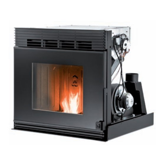
The Boiler is composed of an exchanger in FIREFLECTOR and dual heat development capacity steel, between which air is blown with a fan which once is heated, is distributed in the room. It works by recycling the air in the installation area, or by ducting it externally. It operates only with the door closed, inserted and locked in its housing. Combustion is controlled by means of a radio-frequency electronic control unit and wireless remote control with the following functions: JOLLY SYNTHESIS 68-80 • Ample screen that Remote control display provides an interface with the product, to set function values Cassette fireplace for a pre-existing fireplace and read data on work status. • On and off time setting function Chronothermostat programmed with settable temperature regulation program. - Page 13 They are also fitted with: • Pellet hopper with about 15 kg capacity • “Humidifier” with incorporated water tank to humidify the heating air in the environment and prevent undesired dry throat sensations caused by excessively dry air; it is possible to add some drops of fragrance oils to the water to freshen the air in the home. • A practical drawer to collect the ashes. • Thermal safety device against possible overheating. • Safety device against possible clogging of the flue pipe. • Tangential Fan for hot air exchange in the environment. • Fume exhaust fan. • Electrical resistance to start combustion. WARNING PELLET combustion products must only be used with the combustion chamber door closed. NOTE The chromatic variations of the painted surfaces, especially those in different materials and finishes and subject to different temperatures, cannot be deemed reason for dispute as they depend upon the natural characteristics of the materials and the use of the product.
-
Page 14: Product Identification
05.2 PRODUCT IDENTIFICATION It is COMPULSORY to indicate the product MODEL, the LOT number and SERIAL NUMBER in all communications with the Manufacturer. Identification numbers are printed on the adhesive plate located on the right side of the pellet container as illustrated. Stove performance values measured during inspection tests according to the indicated reference and EC markings are also included on the plate. Product Model Inserto Synthesis 68 CE marking Via San Giuseppe, 2 - 24060 Telgate - BG - * EN 14785:2006 Tel. +39.035.8359211 - fax +39.035.8359200 Year of commisionign and certification www.jolly-mec.it - info@jolly-mec.it Apparecchio funzionanante a pellet -equipment with pellet feeding -betriebene Geräte Pellet - équipement alimentés à... -
Page 15: Chap.06 Technical Data
CHAP.06 TECHNICAL DATA 06.1 HOMOLOGATION Technical specifications resulting from laboratory tests conducted according to EN 14785:2006 test methods at the CERTIFICATION institute. Description mod.68 mod.80 Burning output 11,46 15,86 Nominal heat output 10,03 13,76 Reduced burning output 2,84 Nominal output consumption 2,37 2,69 kg/h Reduced output consumption 0,65 kg/h Nominal output efficiency 87,47 86,76 Reduced output efficiency 90,75 Rated voltage Rated frequency Electrical absorption min(at full capacity) - max(during start-up) 170 - 365 190 - 370 Total weight 105 - 120 (star) 120 - 130 (star) Standard hopper capacity... -
Page 16: Recommended Fuels
06.2 RECOMMENDED FUELS WARNING PELLET QUALITY IS VERY IMPORTANT; PLEASE READ THIS SECTION CAREFULLY A pellet product’s performance is significantly linked and highly influenced by the type and quality of wooden pellets that is burned. It is important to choose pellets that have no debris or impurities. The Association of Pellet Manufacturers with the Italian Thermotechnical Committee have established standards for identifying pellets in terms of energy*. As the efficiencies of different wooden PELLETS qualities differ, likewise the efficiency and heat capacity emitted by the product running on pellets will vary. Similarly, unburned residue left in the combustion chamber is inversely proportionate to pellet quality: the lower the pellet purity, the faster dirt accumulates in the machine. Jolly Mec Caminetti S.p.A strongly recommends the use of the same type of pellets used during first start-up, i.e. when the settings and calibrations were made to suit the loaded combustible materials. Continuous switching of types and qualities of combustible materials will require continuous adjustments to settings by the Technical Assistance Centre, which can not be endorsed by the Manufacturer. The main quality certifications for PELLETS on the European market are DIN Plus, Ö-Norm M7135 and UNI EN ISO 17225-2 (class A1 or A2), which guarantee the following quality standards: *CERTIFIED PELLET CHARACTERISTICS 1% maximum through a 3.2 mm screen Powder 680 Kg/m minimum Apparent density 6 mm diameter from 25 to 30 mm of maximum length Dimensions 1% maximum Ash content 8% maximum Humidity 4,9 kWh/Kg Heating power in eco-compatible or biodegradable material sacks Packaging Store pellets at least 1 m from the appliance, in a dry place and not outdoors, not even under porches or roofings. Do not use pellets that are very hard and with different dimensions; the mechanical parts are sized and tested for use with pellets with the above-mentioned characteristics. -
Page 17: Components
06.3 COMPONENTS The inset fireplace is supplied with an assembled and tested pellet hopper, packed in a cardboard container in a wood box , with polystyrene protection and cellophane hood with the following components: • Usage, maintenance and installation sheet • Control panel with electronic control unit mod. M10-P Components list: Air diffusion grid (It can be opened to extract the pellet loading drawer or adjust the air damper) Electronic control unit Pellet hopper (With front extractable drawer for filling (model Jolly Synthesis); With overhead lateral filling (model Jolly Star) Pressostat Support base with runners Emergency console Combustion fan and fume discharge Runners for inset fireplace extraction Humidifier Accessible by opening the door) 10. Air damper regulating lever (Accessible by opening the air diffusion grid;only Jolly Star mod.) 11. Handle for opening door 12. Door 13. -
Page 18: Optionals
06.4 OPTIONALS Automatic closing box for external Insect- proof grate 230 x 230 air passageway: mm: Installed on the external air Installed on the exterior of the passageway, it only allows for air comburent air intake, it prevents intake when actually necessary, insect entrance within the home. closing the cold air passage when The mesh must be periodically Fume connection pipe Ø80mm: the generator is not running to thus... -
Page 19: Dimensions
06.5 DIMENSIONS All measurements are in mm. - Inset fireplace for pre-existing fireplace JOLLY SYNTHESIS 68-(80) - Inset fireplace for a new fireplace and ducting JOLLY STAR 68-(80) NOTE The pellet chute for loading the hopper can be assembled, according to the cladding that has been chosen on the right, left or front. -
Page 20: Chap.07 Positioning And Connections For The Installer
CHAP.07 POSITIONING AND CONNECTIONS FOR THE INSTALLER 07.1 POSITION OF EXTERNAL AIR INTAKES AND ELECTRIC CURRENT The machine must only be installed on surfaces that can support the load. If the existing construction does not meet this requirement, it will be necessary to take appropriate measures (e.g. installing a load distribution plate). The machine must be installed in an area where the machine, gas exhaust pipes and flue can be easily accessed for cleaning. INSTALLATION IN A PRE-EXISTING FIREPLACE All measurements are in mm. We recommend to mount the box with authomatica closure for the external fresh air entry. Taken outside air exchange Ø120 Create the room with the measurements shown, starting 65mm from the wire glass front Internal air intake Ø80 for air circulation inside environment or to levy combustion air Electrical socket Raceway... -
Page 21: Assembling And Installing The Fireplace In A Pre-Existing Fireplace
F .2). Phase 3: Fasten the attachments (D)(included) for pipes below the support plate (E) using the relative screw (if this solution is provided, see par. 07.1). Phase 4: IInstall and fasten the support plate with the plugs (E) in the cassette fireplace’s definitive position, taking care to carry out these operations IN THE MOST COMPETENT MANNER. The responsibility for the work done for installation does not under any circumstance belong to Jolly Mec S.p.A. it is and remains the responsibility of the installer to verify that the in- stallation solutions are correct and that they comply with all the safety regulations in force in the country in which the product is installed. Put the new flue on the collar (F) of the support plate (see F .4). (1) Inspection plate for easy assembly Phase 5: Remove the two runners and prop the inset fire- place on them, fastening it with the nuts (A) and screws(B) dismounted in ph. 2 (see F... -
Page 22: Assembling And Installing The Fireplace In A New Fireplace
AIR CANALISATION GROUP and PELLET CHUTE ASSEMBLING. Phase 1: Place the fireplace complete with the AIR CANALI- SATION GROUP and PELLET LOAD CHUTE on the floor at the established place. If it cannot be fastened to the floor, fit the brackets in the rear part of the support (see F .1) to fasten it to the wall, making sure these operations are done “IN THE MOST COMPETENT MANNER”. The Responsibility of the work done for installation cannot be considered to belong to Jolly Mec S.p.A. but it is the responsibility of the installer who must verify that the installation solutions are correct and that they comply with all the safety regulations in force in the country in which the product is installed. Phase 2: Vary the height from the ground through the bolts and the holes (H) on the stand(see F .2) and fix at the wall or on the floor through the block strip. Phase 3: Put the new flue on the collar (F) of the support plate (see F ..3). -
Page 23: Air Circulation
07.4 AIR CIRCULATION 1. Fume exhaust 2. Flexible aluminium pipes for hot air ducting: ø80mm for mod. STAR 68, ø100mm for mod. STAR 80, L. max. 2x4m 3. Chute for loading pellets 4. Air damper lever for regulating the flow of ducting 5. Humidifier 6. Obligatory external air intake(see par. 07.1) 7. Ø80mm pipe for combustion air intake be connected to internal or external as required (see par. 07.1) 8. Handle for opening door 9. Air vents for air circulation inside environment or to levy combustion air 10. Door 11. Openable front grid 12. Adjustable vents for hot air 180x120mm 13. Recirculation grid obligatory hood 400x100mm (100mm from the ceiling) 07.5 EXAMPLE OF AIR DUCTING IN THE VARIOUS ROOMS NOTE To duct air into the other rooms, connect the pipes to the fireplace’s upper rear outlets. To distribute air to the various areas, see example. The air can be balanced with the grids with adjustable closures. - Page 24 It is also very dangerous to use plastic pipes to distribute air since the high temperatures could deform them and release harmful gases. Where it is impossible to wall up the distribution pipes, they can be hidden with a suspended ceiling, fake beams or casing. The space between the vents and the wall must be hermetically sealed with silicone (A), to prevent that leaking air blackens it due to heat (for exemple dark spots of the radiators). WARNING IMPORTANT: Use a neutral cure silicone seal...
-
Page 25: Flue Or Fume Exhaust System
07.6 FLUE OR FUME EXHAUST SYSTEM The flue or fume exhaust system is a fundamental element for the proper functioning of the stove and must comply with the following general standards: EN1856-1 Chimneys. Requirements for metal chimneys - Part 1: System chimney products EN1856-2 Chimneys. Requirements for metal chimneys - Part 2: Metal flue liners and connecting flue pipes UNI 10683 Heat generators operating with wood or other solid bio fuels - Installation requirements The diameter of the flue must be sized according to the technical specifications of the appliance and type and place of installation. Each appliance must have its own chimney flue without any inlets from other appliances. The exhaust duct of the combustion products generated by the forced draught equipment must respond to the following requirements: • it is necessary to use union joints and pipes with pressure resistant seals, as the union of the flue could be slightly pressurised while the appliance running • all changes in direction must be open to inspection to facilitate maintenance • correct draught to maintain depression in the combustion chamber, as per the technical specifications, must be guaranteed • it must be watertight, waterproof and suitably isolated and insulated • must be made of suitable materials that resist normal mechanical stress, heat, the action of the combustion products and acid condensations • must be prevailingly vertical structures with deviations from the axis not greater that 45° • must be adequately distanced from combustible or inflammable materials via an air space or suitable insulation • must have an internal section which is preferably circular: square or rectangular sections must have rounded corners with a radius of no less than 20 mm • must have an internal section that is constant, free and independent If the flue is installed externally it must be insulated to prevent the cooling of fumes and formation of condensation. The same is valid for the tract from the roof to the chimney cap (Torrino). For the union between the stove and the flue, or if there are deviations or curves, for easier, quicker and safer installation, we recommend using double-walled stainless steel pipes. -
Page 26: Installation Room Ventilation
In the event of a black-out, suitable sizing of the fume exhaust system guarantees sufficient draught to exhaust the fumes generated by combustion without the use of the electric exhaust fan. If the performance of the fume exhaust system is not excellent, it is possible to adjust the operating settings of the stove to overcome draught defects by a maximum of 15% of the fume exhaust device; this adjustment is however the exclusive competence of the Technical Assistance Centre CAT. One airtight reading point is recommended on the flue to check emissions after installation and measure draught. Supporting the weight of the flue with the appliance union is strictly forbidden. Use specific stands or independent supports for this purpose. To install other combustion devices in the same room where the pellet appliance is installed, refer to UNI 10683 and UNI 7129 installation regulations. The minimum flue height must be over 3,0 m. Blocking of wall exhaust terminals at any height and any distance from openings, doors and/or windows is not permitted and a very important rule to follow. Installation of external fireplaces must be performed using insulated double-walled pipes, to prevent the formation of condensate; it must also be possible to inspect the base of the fireplace for routine maintenance which must be done at least once a year. A windproof chimney cap must be installed; in the presence of adverse weather conditions, especially high winds, this accessory allows the stove flue draught system to operate much easier. A minimum flue draught between 10 and 14 Pa must be guaranteed. This value must be measured using specific and controlled instruments each time the appliance and flue undergo maintenance. With strong winds and the chimney cap installed in the reflux area (see F .2, zone bordered by the dotted line A for roofs with ß>10° slant) of the roof or without complying with the distances foreseen by UNI 10683 situations may arise where the stove does not work which will trigger the no depression alarm. It is not possible to make corrections or reset the stove operating values to override the alarm. ß>10° 07.7 INSTALLATION ROOM VENTILATION According to reference regulation UNI10683, 4 Pa depression must be verified between the installation room interior and exterior. Prepare adequate ventilation openings in the room where the product is installed to permit at least 50 m³/h clean comburent air flow not taken from polluted rooms. The ventilation openings, if fitted with insect-proof mesh, must be easily removable and undergo periodic cleaning to ensure clear air flow passage. If the comburent air inlet is directly connected to the stove, it may be necessary to make adjustments to the control unit, especially during the start-up phase, as the temperature and humidity of outdoor air not only varies during the period of use of the product, but also come into direct contact with the pellets and the ignition element, generating different fuel burning times. Jolly Mec allows the ducting system at the input of the combustion air within and not over the following limits: the length can’t be longer that 1000 mm, the diameter has to have at least the same section of the stove/boiler connection, it is possible only one 90° change of direction, the center-to-center distance of the combustion air input pipe can be ± 300 mm. WARNING As for the fuel product exhaust system, air vents are also extremely important and must be given the appropriate consideration and respect. -
Page 27: Electrical Connections
07.8 ELECTRICAL CONNECTIONS WARNING Electrical connections must be carried out by skilled personnel according to the regulations in force (2014/30/UE and 2014/35/UE). Connect the 230Vac 50Hz line with the proper cable with plug, supplied with the stove, which powers up the control unit and all the appliance’s electrical components. The device is equipped with a power socket and fuse (A), a spare fuse in the drawer (B) and a bipolar switch (C) (see see fig. alongside). L’apparecchio è dotato di una presa di corrente con fusibile (A), fusibile di scorta nel cassetto (B) e di un interruttore elettrico bipolare generale (C) (vedi figura a lato). In the event that the control unit does not switch on, even after turning the switch to I “ONE”, check... -
Page 28: Control Unit Electrical Wiring Diagram
07.10 CONTROL UNIT ELECTRICAL WIRING DIAGRAM WARNING Electrical connections must be carried out by skilled personnel according to the regulations in force (2014/30/UE and 2014/35/UE). BLUE BLACK Y - G BROWN BROWN BLUE ORANGE ORANGE PURPLE PURPLE PINK GREY PINK BLACK WHITE WHITE BLUE Fume safety pressure switch User Radio Console Electronic control pannels PELLET auger motor Socket with bipolar switch and fuse holder for the electric Room temperature probe network Fume temperature probe... -
Page 29: Chap.08 Use And Maintenance For The User
CHAP.08 USE AND MAINTENANCE FOR THE USER 08.1 APPLIANCE OPERATIONS The inset FIREPLACE uses pellets as fuel, whose combustion is electronically controlled. Pellets are taken from the storage hopper (A) by the auger B) controlled by the gear motor (C) and conveyed directly to the combustion crucible (D). They are ignited by the hot air produced by the electric heating element (E) and aspirated into the crucible by the centrifugal fan (F) which is the same that sucks up the fumes produced by combustion, expelling them from the large vent located on the upper part of the support plate and connected with the flue. The fan (G) moves air in the air space on the back of the fireplace, where it is heated and then released into the environment through the slot and the front grid (H) and/or ducting(L). The hopper (A), on the rear part of... -
Page 30: Emergency Console
08.3 EMERGENCY CONSOLE If the remote control breaks down, the basic functions can be accessed by an emergency console (see also REMOTE CONTROL MANUAL M10-P AIR attachment), located under the control unit lid inside the cassette fireplace on the left side(see photo). To access the console, you must extract the cassette fireplace as explained in the preceding paragraph 08.2, then remove the console holder,which is fixed on two pins, cut the plastic band binding the cable and bring everything up to the door. Inside the door below to the left, there are two pins on which the console holder bracket can be fastened, fixing it so it stays turned outward, and making sure to thread the cable in the remaining space between the base and the door in order not to crush it. -
Page 31: Recommendations And Warnings
08.6 RECOMMENDATIONS AND WARNINGS The fan begins to run automatically following the smokes temperatures. WARNING NEVER RUN THE FIREPLACE WITHOUT ELECTRICAL CURRENT AND WITH FUELS OTHER THAN WOOD PELLETS The humidifying water (max capacity 1 litre) must be manually inserted in the fireplace through the filling window that is located to the right of the fireplace, beneath the air diffusion grid (the humidifier is full when the water reaches the level). Do remember that the fireplace can also operate without water Air humidificaton prevents physiological disorders such as: dry throat, migraine, various allergies and excess dust caused by... -
Page 32: Ordinary Maintenance (To Be Done By The Customer)
08.7 ORDINARY MAINTENANCE (to be done by the customer) For the first few days during pellet operation, keep the pellet basket under observation to determine after how many days it must be cleaned, as different qualities of pellets have different quantities of residue. WARNING Before starting any type of cleaning, switch off the main switch and make sure that the fireplace is cold. • Pellet basket cleaning (recommended 2-5 days) Eliminate any debris in the basket, turning it over with a tool and with its tip remove any material that may be clogging it, striking the inner walls of the basket then shaking it; or remove the basket completely from its housing to make cleaning easier. Clean the air passage holes in the basket carefully with a pointed tool. Make sure that the area where the basket rests is cleaned well (if the basket does not sit well on it and air passes, the fireplace will not start up and operates poorly; it can also let returning smoke enter the pellet hopper) Reposition the pellet basket perfectly. • Glass cleaning (daily) Clean the glass daily with a damp sponge or paper towel. If the glass becomes dirty with black smoke, the, pellet basket is probably dirty or the combustion air must be increased. Be careful not to use overly aggressive products to avoid ruining the paint. Never spray detergents directly onto the parts to be cleaned. If the fireplace requires more frequent and deeper cleaning, check the flue draught performance and the chimney cap. A windproof chimney cap is strongly recommended. - Page 33 . 8) remove it from the fireplace. Clean the boiler’s internal surfaces with a brush (see F . 9-10- 11). With a vacuum specific (can) or palette and brushes clean the ashes and residues. Reassemble all parts following the sequence carefully. * Recommended cleaning once a month (but check the manual). . 10 . 11 • Loading the pellet hopper (Jolly Synthesis 68-80 model) The pellet hopper is filled through the opening on the hot air diffusion grid (F . 12). Remove the pellet drawer (F . 13) 13and pour the pellets into the drawer using a shovel (not supplied) (F . 14). The pellets must not be poured in directly from the sack. As seen in (F 15) use the designated tool to push the pellets inside the pellet hopper. When loading has been completed, close the drawer and grid. It is recommended to fill the hopper when the device is cold and switched off. If the hopper is filled up when the device is running or hot, it is compulsory to wear the heat protection glove provided as, during these phases, the surfaces of the ventilation grid the load drawer handle can get extremely hot. . 12 . 13 .
-
Page 34: Preventive Maintenance Program (To Be Done By The Authorised Jolly-Mec Technical Assistance Centre)
• Loading the pellet hopper (Jolly Star 68-80 model) The pellet loading chute is used to fill up the pellet hopper. Access the chute via the flap on the cladding, as seen in the cladding example F . 16 (F . 16-17-18). Pour in the pellets using a shovel (not supplied) (F . 19). The pellets must not be poured in directly from the sack. . 16 . 17 . 18 . 19 08.8 PREVENTIVE MAINTENANCE PROGRAM (to be done by the authorised Jolly-Mec Technical Assistance Centre) We wish to remind you that the Extraordinary Maintenance to be carried out on this type of fireplace must be done obliga- torily every year by qualified maintenance personnel, in order to maintain its functionality, efficiency and comfort. -
Page 35: Chap.09 Fault Diagnosis And Troubleshooting
CHAP.09 FAULT DIAGNOSIS AND TROUBLESHOOTING 09.1 PROBLEMS WARNING Do not use the stove if the uptake is irregular and the combustion is not optimal! • In accordance with the laws in force on safety for electrical appliances, a Jolly Mec Technical Assistance Centre or • qualified personnel must obligatorily be contacted for all installation, maintenance or interventions that require access to electrical parts. PROBLEM MAIN CHECKS TO BE PERFORMED The Emergency Console is • Check that the fireplace plug is inserted securely in the mains socket and the socket at the back of the fireplace. not on • Check that the FLAT cable is connected to the electronic circuit board correctly. • Check that the protection fuses are working efficiently, including those connected to the electronic circuit board and those in the fireplace socket. • Check that the batteries are not dead and they are inserted correctly. Rechargeable batteries are bot The remote control allowed. does not work •... -
Page 36: Alarm Messages
09.2 ALARM MESSAGES Following is an overview on appliance alarms linked to the probable causes and some potential solutions. If an alarm occurs with a certain frequency, contact the Jolly Mec Technical Assistance Centre. Alarm Alarm Cause Main reason Main solution Code Text • Electrical black out while the • The electric plug has disconnected from • Check that the power cord is connected AL01 BLACK fireplace is running the mains socket properly to both the mains socket and the fireplace socket • The electric plug has disconnected from the fireplace socket • Check that the connectors are well connected to the electronic circuit board • The electrical wiring connector has terminal board (test this with the power disconnected from the electronic circuit cord disconnected) - Page 37 Alarm Alarm Cause Main reason Main solution Code Text • The temperature falls below • There are no PELLETS in the hopper • Check that the level of PELLETS inside AL06 empty the THRESHOL LAVORO the hopper is sufficient • The level of PELLETS is so low that the pellet setting whilst the stove is flame can not stay alight • Check the PELLET load times are set running. correctly • The THRESHOL LAVORO setting has • Fume probe is faulty...
-
Page 38: Chap.10 Attachments
CHAP.10 ATTACHMENTS 10.1 JOLLY STAR 68/80 - AIR CANALISATION GROUP AND PELLET CHUTE ASSEMBLING The fireplace JOLLY STAR 68/80 is delivered completely assembled on its easel (see F . 1) and complete with the required component to fix it and the components of the canalisation group and pellet load chute (see F . 2). 10.1.1 Components for canalisation group and for pel- let chute system 1. Lateral shaft to fix the easel (n° 2 pcs.) 2. Assemble the lateral shaft for canalisation (nr.2 pcs.) 3. Top bar 4. Hot air box... - Page 39 10.1.2 For a correct assembling of the following parts: Fix the lateral shaft 1 (F . 3), using the screws M8x16 with their nuts and washers, in the equipment, following the installation type. Fix the lateral shafts 2 (F . 4), using the screws M8x16 with their nuts and washers, without tightening it, only preassembly it.
- Page 40 10.1.2 For a correct assembling of the following parts: Fix the hot air box 4 (F . 6), using the screws (nr.3) M5x16, without tightening it, only preassembly it. Now follow by adjusting the hot air box till it fits properly with the fireplace, to avoid air losses: • By acting on the upper part of the lateral shafts you can adjust the top bar up and down (fig.A). • By acting on the lower part of the lateral shafts you obtain a regulation in deep of the top bar (fig.B). • By acting on the top bar, using the three slots you obtain an adjustment of the hot air box (fig.C). Fig. A Fig. B Before tightening the screws through the nut and the washer, verify the good placement of the hot air box and check that by sliding the fireplace in and out everything is fitting correctly (see the included instruction manual for the opening). WARNING Before you start to extract the fireplace, verify that it is properly fixed on a wall or at the floor to avoid a roll over which could be dangerous.
- Page 41 10.1.2 For a correct assembling of the following parts: Assemble the sliding group (F . 8), with the screws M8x16 the nuts and the washers in the equipment, inside the upper bar with the help of the upper holes, depending from the position chosen and fix tightly. Using the two lateral screws (F . 9) on the sliding group you can adjust the distance of the chute to the cladding (F . 10). . 10 Lateral screws...
- Page 42 NOTES...
- Page 44 Via S.Giuseppe 2 - 24060 Telgate (Bg) Italy Tel. +39 035.83.59.211 Fax +39 035.83.59.203 www.jolly-mec.it - info@jolly-mec.it...
Need help?
Do you have a question about the JOLLY SYNTHESIS 68-80 and is the answer not in the manual?
Questions and answers