
Subscribe to Our Youtube Channel
Related Manuals for Ruijie RG-CS83 Series


Summary of Contents for Ruijie RG-CS83 Series
- Page 1 Ruijie RG-CS83 Series Switches Hardware Installation and Reference Guide Document Version: V1.0 Date: 2023.08.20 Copyright © 2023 Ruijie Networks...
- Page 2 All rights are reserved in this document and this statement. Any reproduction, excerption, backup, modification, transmission, translation or commercial use of this document or any portion of this document, in any form or by any means, without the prior written consent of Ruijie Networks is prohibited.
- Page 3 Preface Intended Audience This document is intended for: Network engineers Technical support and servicing engineers Network administrators Technical Support Ruijie Networks Website: https://www.ruijienetworks.com/ Technical Support Website: https://ruijienetworks.com/support Case Portal: https://caseportal.ruijienetworks.com Community: https://community.ruijienetworks.com ...
- Page 4 Warning An alert that calls attention to important rules and information that if not understood or followed can result in data loss or equipment damage. Caution An alert that calls attention to essential information that if not understood or followed can result in function failure or performance degradation.
-
Page 5: Product Overviews
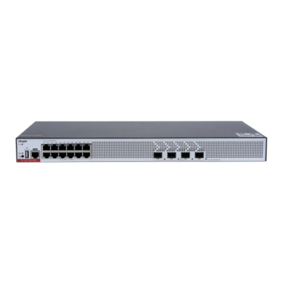
Hardware Installation and Reference Guide 1 Product Overviews The RG-CS83 series switches are new generation layer 3 switches, providing high performance, consolidated security and multiple services. The switches are mainly applied to the access layer to provide line-rate switching and complete QoS policies, prioritizing some traffic over others to ensure important data transmission without lantency. -
Page 6: Specifications
SFP+ Modules, SFP+ Cables and SFP+ BIDI Modules. SFP Module Type See Chapter 7 for details. The module types may update without prior notification. Please contact Ruijie Networks for details. AC Input Rated Voltage Range: 100 V AC to 240 V AC... -
Page 7: Front Panel
Hardware Installation and Reference Guide Fan Speed Control (manual configuration not supported) Fan Fault Alarming Temperature Supported Alarming EMI Certification GB/T 9254.1 Safety Regulation GB 4943.1 Compliance Dimensions 442mm × 220mm × 43.6mm (17.4in x 8.66in x 1.72in ) (W x D x H) Weight 3kg (6.61 lbs.) (The product information label is on the bottom of the switch.) Appearance... -
Page 8: Back Panel
Hardware Installation and Reference Guide Note 1. System Status LED 5.Console Port 6 . 10/100/1000Base-T Ethernet 2.LED Mode LED 3.LED Mode button Port 4.USB Port 7.10GE SFP+ Port 8.Port Status LED Back Panel Figure 1-2 Back Panel of RG-CS83-12GT4XS-P Note 1.AC Power Plug 2.Grounding Stud Power Supply Module... - Page 9 Hardware Installation and Reference Guide Function Panel ID Color Status System is not powered on. Blinking System is being initialized. Continuous blinking Green (3 indicates a fault. Blinking Green (10 System is being located. System Status LED Status Solid System is operating normally. Green Solid The temperature at the air intake and exhaust...
- Page 10 SFP Modules and SFP BIDI Modules SFP+ Modules, SFP+ Cables and SFP+ BIDI Modules. See Chapter 7 for details. The module types may update without prior notification. Please contact Ruijie Networks SFP Module Type for details. When up to two SFP+ optical modules are configured with a maximum distance of 80 km (49.71 miles), the operating temperature range is 0º...
- Page 11 Hardware Installation and Reference Guide Safety Regulation GB 4943.1 Compliance Dimensions 442mm × 220mm × 43.6mm (17.4in x 8.66in x 1.72in ) (W x D x H) Weight 3kg (6.61 lbs.) (The product information label is on the bottom of the switch.) Appearance The front panel of the RG-CS83-24GT4XS...
-
Page 12: Power Supply
Hardware Installation and Reference Guide 4 . 10/100/1000Base-T Ethernet Note 1.System Status LED 2.USB Port Port 3.Console Port 5.10GE SFP+ Port 6.Port Status LED Back Panel Figure 1-7 Back Panel of RG-CS83-24GT4XS Note 1.AC Power Plug 2.Grounding Stud Power Supply The RG-CS83-24GT4XS switch has a built-in power supply module. - Page 13 SFP+ Modules, SFP+ Cables and SFP+ BIDI Modules. SFP Module Type See Chapter 7 for details. The module types may update without prior notification. Please contact Ruijie Networks for details. AC Input Rated Voltage Range: 100 V AC to 240 V AC...
- Page 14 Hardware Installation and Reference Guide The PoE+ port is compliant with both the PoE (IEEE802.3af) and PoE+ (IEEE802.3at) standards. The maximum number of PoE devices supported by the switch is determined by the available PoE consumption of the switch and the actual PoE consumption of each device.
- Page 15 Hardware Installation and Reference Guide Front Panel Figure 1-9 Front Panel of RG-CS83-24GT4XS-P Note 1.System Status LED 5.Console\ Port 6 . 10/100/1000Base-T Ethernet 2.LED Mode LED 3.LED Mode button Port 4.USB Port 7.10GE SFP+ Port 8.Port Status LED Back Panel Figure 1-10 Back Panel of RG-CS83-24GT4XS-P Note 1.AC power plug...
- Page 16 Hardware Installation and Reference Guide The RG-CS83-24GT4XS-P switch has a built-in power supply module. The back panel has an an AC power plug. Cooling The RG-CS83-24GT4XS-P switch adopts a left-to-right and front-to-right airflow to ensure normal operation. Maintain a minimum clearance of 100 mm (3.94 in.) around the device for air circulation. Figure 1-11 Airflow Direction Function Panel ID...
- Page 17 SFP+ Modules, SFP+ Cables and SFP+ BIDI Modules. SFP Module See Chapter 7 for details. The module types may update without prior notification. Please contact Ruijie Networks for details. AC Input Rated Voltage Range: 100 V AC to 240 V AC...
- Page 18 Hardware Installation and Reference Guide Power Consumption <40W Ambient Noise 32dB(A) 0º C to 45º C (32º F to 113 º F) at a height below 1800 m (1.12 miles) above the sea level At a height ranging from 1800 m (1.12 miles) to 5000 m (3.11 miles) above the sea level, the Temperature maximum operating temperature decreases by 1°...
- Page 19 Hardware Installation and Reference Guide Front Panel Figure 1-13 Front Panel of RG-CS83-48GT4XS 4 . 10/100/1000Base-T Ethernet Note 1.System Status LED 2.USB Port Port 3.Console Port 5.10GE SFP+ Port 6.Port Status LED Back Panel Figure 1-14 Back Panel of RG-CS83-48GT4XS Note 1.AC Power Plug 2.Grounding Stud...
- Page 20 Hardware Installation and Reference Guide The RG-CS83-48GT4XS switch has a built-in power supply module. The back panel has an AC power plug. Cooling The RG-CS83-48GT4XS switch adopts a left-to-right and front-to-right airflow to ensure normal operation. Maintain a minimum clearance of 100 mm (3.94 in.) around the device for air circulation. Figure 1-15 Airflow Direction Function Panel ID...
- Page 21 SFP+ Modules, SFP+ Cables and SFP+ BIDI Modules. SFP Module Type See Chapter 7 for details. The module types may update without prior notification. Please contact Ruijie Networks for details. AC Input Rated Voltage Range: 100 V AC to 240 V AC...
- Page 22 Hardware Installation and Reference Guide Storage Temperature -40º C to 70º C (-40º F to 158º F) Operating Humidity 10% to 90% RH (non-condensing) Operating Height 0 to 5000 m (3.11 miles) above the sea level Storage Humidity 5% to 95% RH (non-condensing) Fan Speed Control (manual configuration not supported) Fan Fault Alarming Temperature...
- Page 23 Hardware Installation and Reference Guide Front Panel Figure 1-17 Front Panel of RG-CS83-48GT4XS-P Note 1.System Status LED 5.Console Port 6 . 10/100/1000Base-T Ethernet 2.LED Mode LED 3.LED Mode button Port 4.USB Port 7.10GE SFP+ Port 8.Port Status LED Back Panel Figure 1-18 Back Panel of RG-CS83-48GT4XS-P Note 1.AC Power Plug...
- Page 24 Hardware Installation and Reference Guide Function Panel ID Color Status System is not powered on. Blinking System is being initialized. Continuous blinking Green (3 indicates a fault. Blinking Green (10 System is being located. System Status LED Status Solid System is operating normally. Green Solid The temperature at the air intake and exhaust...
-
Page 25: Preparing For Installation
Hardware Installation and Reference Guide Solid PoE is enabled. The port is operational. Green Blinking Green(3 The port has a PoE fault of overload. LED Mode Button: The LED Mode button is used to switch the LED mode. The green LED Mode indicator indicates the switching status. Press the LED Mode button, and the LED Mode indicator will turn yellow, indicating the PoE status. -
Page 26: Electrostatic Discharge Safety
Hardware Installation and Reference Guide Make sure that the device is powered off when you cut off the power supply. Do not place the switch in a wet position, and keep the switch away from liquid. Any nonstandard and inaccurate operation can cause an accident such as fire or electrical attack, thus causing severe damages to human bodies and device. -
Page 27: Installation Environment Requirements
Hardware Installation and Reference Guide Do not stare at any fiber port. 2.1.6 Storage Security To ensure the normal operation of the device, maintain a proper storage environment in accordance with the storage temperature/storage humidity requirements in the technical specifications table of the corresponding device. If the storage time exceeds 18 months, you must power on the device and keep it running for 24 hours without interruption for device activation. - Page 28 Hardware Installation and Reference Guide Maximum concentration 1.4 x 10 7 x 10 2.4 x 10 1.3 x 10 (Particles/m³ ) Apart from dust, the salt, acid, and sulfide in the air in the equipment room must meet strict requirements. These harmful substances will accelerate metal corrosion and component aging.
-
Page 29: Lightning Protection Requirements
Hardware Installation and Reference Guide Grounding required for electromagnetic compatibility includes shielded grounding, filter grounding, noise and interference suppression, and level reference, which contribute to the overall grounding requirements. The grounding resistance should be smaller than 1 ohm. The back panel has one Grounding Stud. Figure 2-1 Grounding 2.2.6 Lightning Protection Requirements The external lightning protection cable row shall be used on the AC power port to prevent the switch from being struck by... - Page 30 Special Tools ESD gloves, wire stripper, crimping plier, RJ45 crimping plier, and wire cutter Cleaning Tools Dust-free paper, fiber end-face microscope Meters Multimeter, bit error rate tester (BERT), optical power meter No tool kit is delivered with the RG-CS83 series switches.
-
Page 31: Installing The Switch
Hardware Installation and Reference Guide 3 Installing the Switch The RG-CS83 series multi-GE switches must be installed indoors. Ensure that requirements in Chapter 2 are all met. 3.1 Installing Procedure Prepare for installation Mount the switch into the rack Ground the switch... -
Page 32: Mounting The Switch In A Rack
3.3.1 Mounting the Switch in a Rack All models of the RG-CS83 series switches can be installed in a standard 19-in. four-post EIA rack. Mount the switch in the rack with the front panel face forward. - Page 33 Hardware Installation and Reference Guide Secure the switch on the rack rails by tightening the screws. Figure 3-3 Tightening Screws Insert screws into the other two cage nuts and tighten them. Figure 3-4 Tightening Other Screws...
-
Page 34: Installing The Switch On A Workbench
Hardware Installation and Reference Guide 3.3.2 Installing the Switch on a Workbench In most cases, users do not have a standard 19-inch rack. Therefore, the most popular method is to place the switch on a clean workbench. Attach the four rubber pads to the four corners on the bottom. ... -
Page 35: Grounding The Switch
Hardware Installation and Reference Guide 3.4 Grounding the Switch Connect the PGND to the grounding lug of the rack and then connect the grounding lug to the grounding bar of the equipment room. Notes The sectional area of the grounding wire should be determined according to the possible maximum current. Cables of good conductor should be used. -
Page 36: Verifying Installation
Hardware Installation and Reference Guide The power cords and other cables should be bundled in a visually pleasing way. When you bundle fibers, make sure that the fibers at the connectors have natural bends or bends of large radius. ... -
Page 37: Connecting An Ethernet Cable
Hardware Installation and Reference Guide Connecting an Ethernet Cable Plug the crystal head of the Ethernet cable into the network port of the PC. Connect the RJ-45 end to the Console port on your AC. Setting Parameters Start the PC and run the terminal simulation program on your PC, for example, PuTTY of Windows 95/98/NT/2000/7/8/10. - Page 38 Hardware Installation and Reference Guide Select Serial, and enter the serial port in Serial line and baud rate in Speed. Fugure 4-3 Select Serial. The serial port parameter setting page is displayed. Set Speed to 9600, Data bits to 8, Stop bits to 1,...
- Page 39 Hardware Installation and Reference Guide Parity to None, and Flow control to None. Figure 4-4 Click Open and the HyperTerminal window will appear.
-
Page 40: Powering On Switch
Hardware Installation and Reference Guide 4.2 Powering on Switch Checklist before Power-on The switch is fully grounded. The power cord is properly connected. The power cord retention clip secures the input power cord to the power supply. ... -
Page 41: Cooling System Maintenance
Hardware Installation and Reference Guide Fan and power supply status System temperature For the monitoring commands, see RG-CS83 Series Switches Configuration Guide. 5.2 Maintenance Cooling System Maintenance If the fan module fails, an alarm will be generated. -
Page 42: Troubleshooting Flowchart
Check the installation of other modules Check the LEDs on the device Check serial port connection and parameters Check the cable connection Contact Technical Support of Ruijie Networks 6.2 Troubleshooting Fault 1: The login password is forgotten. Symptom Failed to log into the system. - Page 43 Check whether the configuration of the serial port on the HyperTerminal is consistent with that in Configuration Guide. If there is still no output on the serial port, please contact Ruijie technical support. Fault 4: The serial port console output is garbled.
- Page 44 Hardware Installation and Reference Guide Check whether the receiving end and transmitting end are reversed. The transmitting end of a fiber port must be connected to the corresponding receiver at the other end. You can confirm both ends by exchanging the connection order of two fiber-optic cables.
-
Page 45: Fiber Connection
Hardware Installation and Reference Guide 10BASE-T uses Category 3, 4, 5 100-ohm UTP/STP and 1000BASE-T uses Category 5 100-ohm UTP/STP for connections. Both support a maximum length of 100 meters. Table 7- shows 100BASE-TX/10BASE-T pin assignments. Table 7- 1 100BASE-TX/10BASE-T Pin Assignments Socket Plug Input Receive Data+... -
Page 46: Mini-Gbic Modules
We provide appropriate SFP modules (Mini-GBIC modules) according to the port types. You can select the module to suit your specific needs. Besides, the Mini-GBIC-GT module is also supported. The following models and technical specifications of some SFP modules are listed for your reference. See Ruijie Transceiver Installation and Reference Guide for details. - Page 47 Hardware Installation and Reference Guide MINI-GBIC-LH40- SMF2 (LC 1310 SM1310 connector) MINI-GBIC-ZX50- SMF2 (LC 1550 SM1550 connector) MINI-GBIC-ZX80- SMF2 (LC 1550 SM1550 connector) MINI-GBIC-ZX100- SMF2 (LC 1550 SM1550 connector) Table 7-3 SFP Copper Module Standard 1000Base-T SFP Module Support DDM (Yes/No) 1000Base-T Mini-GBIC-GT Table 7-4 Cabling Specifications...
- Page 48 Hardware Installation and Reference Guide MINI-GBIC- SMF2 (LC connector) 9/125 80 km ZX80-SM1550 MINI-GBIC- SMF2 (LC connector) 9/125 100 km ZX100-SM1550 SDH155-SFP- MMF1 (MPO connector) 62.5/125 500 m SX-MM850 SDH155-SFP- MMF1 (MPO connector) 62.5/125 2 km SX-MM1310 SDH155-SFP- SMF2 (LC connector) 9/125 15 km LH15-SM1310...
-
Page 49: Sfp Modules
We provide appropriate SFP+ modules according to the port types. You can select the module to suit your specific needs. The following models and technical specifications of some SFP+ modules are listed for your reference. See Ruijie Transceiver Installation and Reference Guide for details. - Page 50 Hardware Installation and Reference Guide 500 (OM2) 82 m 400 (OM1) 66 m XG-SFP-SR- MMF1 (MPO connector) 50/125 2000 (OM3) 300 m SM1270-BIDI XG-SFP-SR- MMF1 (MPO connector) 50/125 2000 (OM3) 300 m SM1330-BIDI XG-SFP-LR- SMF2 (LC connector) 9/125 10 km SM1270-BIDI XG-SFP-LR- SMF2 (LC connector)
- Page 51 Hardware Installation and Reference Guide Speed/Distance Paring Models XG-SFP-SR-SM1270-BIDI 10-Gigabit/300 m XG-SFP-SR-SM1330-BIDI XG-SFP-LR-SM1270-BIDI 10-Gigabit/10 km XG-SFP-LR-SM1330-BIDI BIDI modules must be used in pairs. If XG-SFP-SR-SM1270-BIDI is used at one end, then XG-SFP-SR-SM1330- BIDI must be applied to the other end.
-
Page 52: Lightening Protection
Hardware Installation and Reference Guide 7.4 Lightening Protection Installing AC Power Arrester (Lightning Protection Power Strip) The AC power port must be connected to an external lightning protection power strip to prevent the switch from being struck by lightning when the AC power cord is introduced from the outdoor and directly connected to the power port of the switch. - Page 53 Hardware Installation and Reference Guide Please connect an Ethernet port arrester to the switch to prevent the damage by lightning before connecting an outdoor Ethernet cable to the switch. Tools: Phillips screwdrivers or flat-head screwdriver, multimeter, and diagonal pliers Installation Steps: Tear one side of the protective paper for the double-sided adhesive tape and paste the tape to the housing of the Ethernet port arrester.
- Page 54 Hardware Installation and Reference Guide grounding. Incomplete arrester installation. If there is more than one port connected to the peer device on the switch, arresters need to be installed on all connection ports for the purpose of lightning protection.
- Page 55 Hardware Installation and Reference Guide 7.5 Cabling When the switch is installed in a standard 19-inch rack, secure the cables around the cable management brackets. Top cabling or bottom cabling is adopted according to the actual situation in the equipment room. All transferred cable connectors should be placed at the bottom of the rack in an orderly manner instead of outside the rack that is easy to touch.
- Page 56 Hardware Installation and Reference Guide Cables of different types (such as power cords, signal cables, and ground cables) should be separated in cabling and bundling. Mixed bundling is disallowed. When they are close to each other, it is recommended to adopt crossover cabling.
- Page 57 Hardware Installation and Reference Guide Cables not to be assembled or remaining parts of cables should be folded and placed in a proper position of the rack or cable trough. The proper position refers to a position that does not affect device running or damage the switch or cable.
-
Page 58: Site Selection
Hardware Installation and Reference Guide Do not use self-tapping screws to fasten terminals. Power cords of the same type and in the same cabling direction should be bundled up into cable bunches, with cables in cable bunches clean and straight. ... - Page 59 Hardware Installation and Reference Guide for flame retarding, soundproofing, heat absorption, dust reduction, and electromagnetic shielding. Keep the door and the window closed to make the machine room sealed. The steel door is recommended for soundproofing. Sulfur-containing materials are forbidden. ...
Need help?
Do you have a question about the RG-CS83 Series and is the answer not in the manual?
Questions and answers