Ruijie Reyee RG-ES106D-P Series Hardware Installation And Reference Manual
Hide thumbs
Also See for Reyee RG-ES106D-P Series:
- Hardware installation and reference manual (83 pages) ,
- Hardware installation and reference manual (48 pages) ,
- Hardware installation and reference manual (58 pages)

Subscribe to Our Youtube Channel
Related Manuals for Ruijie Reyee RG-ES106D-P Series


Summary of Contents for Ruijie Reyee RG-ES106D-P Series
- Page 1 RG-ES106D-P, RG-ES126S-LP, RG-ES110D-P, RG-ES118S-LP, RG-ES116G, RG-ES124GD Series Switch Hardware Installation and Reference Guide Document Version: V1.2 Date: 2023-02-15 Copyright © 2023 Ruijie Networks...
- Page 2 Ruijie Networks reserves the right to modify the content of the document without any notice or prompt. This manual is designed merely as a user guide. Ruijie Networks has tried its best to e nsure the accuracy and reliability of the content when compiling this manual, but it does not guarantee that the content of the manual is completely free of errors or omissions, and all the information in this manual does not constitute any explicit or implicit warranties.
- Page 3 Ruijie RG-ES100 Series Switches Hardware Installation and Reference Guide Preface Thank you for using our products. This manual will guide you through the installation of the device. This manual describes the functional and physical features and provides the device installation steps, hardware troubleshooting, module technical specifications, and specifications and usage guidelines for cables and connectors.
-
Page 4: Product Overview
Ruijie RG-ES100 Series Switches Hardware Installation and Reference Guide Warning An alert that calls attention to important rules and information that if not understood or followed can result in data loss or equipment damage. Caution An alert that calls attention to essential information that if not understood or followed can result in function failure or performance degradation. - Page 5 Ruijie RG-ES100 Series Switches Hardware Installation and Reference Guide Rated voltage range: 100 V AC to 240 V AC Maximum voltage range: 90 V AC to 264 V AC Frequency: 50/60 Hz Rated current: 1.5 A Adapter output Rated voltage range: 51 V DC Rated current range: 1.25 A...
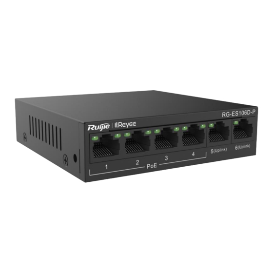
- Page 6 Ruijie RG-ES100 Series Switches Hardware Installation and Reference Guide Figure 1-1 Appearance of the RG-ES106D-P Front Panel Figure 1-2 Front Panel of the RG-ES106D-P Note: 1. Electrical port status LED 2. PoE status LED 3. 10/100Base-TX PoE port 4. 10/100Base-TX auto-sensing Ethernet port 5.
- Page 7 Ruijie RG-ES100 Series Switches Hardware Installation and Reference Guide Note: 1. Port mode switchover button 2. System status LED 3. DC power socket 4. Grounding pole Heat Dissipation The RG-ES106D-P adopts natural heat dissipation, thereby ensuring normal operation. You must maintain a minimum clearance of 100 mm (3.94 in.) around the RG-ES106D-P.
- Page 8 Ruijie RG-ES100 Series Switches Hardware Installation and Reference Guide Model RG-ES126S-LP Ports 1 to 24 are 10/100Base-TX auto-sensing Ethernet ports, and support PoE/PoE+. Ports 25 and 26 are 10/100/1000Base-T auto-sensing Ethernet ports, and do not support PoE Ports or PoE+.
- Page 9 Ruijie RG-ES100 Series Switches Hardware Installation and Reference Guide Product Appearance The RG-ES126S-LP provides twenty-four 10/100Base-TX auto-sensing Ethernet ports, two 10/100/1000Base-T auto- sensing Ethernet ports, one 1000Base-X SFP port, system status LEDs , a port mode switchover button on the front panel, and a power socket and a grounding pole on the back panel.
- Page 10 Ruijie RG-ES100 Series Switches Hardware Installation and Reference Guide Note: 1. Grounding pole 2. AC power socket Heat Dissipation The RG-ES126S-LP adopts fans for heat dissipation, thereby ensuring normal operation. You must reserve 10 cm distance space at both sides and the back plane of the cabinet to allow airflow. It is recommended that you clean the RG-ES126S- LP once every 3 months to avoid dust from blocking vents.
- Page 11 Ruijie RG-ES100 Series Switches Hardware Installation and Reference Guide Rated voltage range: 100 V AC to 240 V AC Maximum voltage range: 90 V AC to 264 V AC Frequency: 50/60 Hz Rated current: 1.6 A Adapter output Rated voltage range: 53.5 V DC Rated current range: 2.24 A...
- Page 12 Ruijie RG-ES100 Series Switches Hardware Installation and Reference Guide The RG-ES110D-P provides eight 10/100Base-TX auto-sensing Ethernet ports, two 10/100/1000Base-T auto-sensing Ethernet ports, and LED indicators on the front panel, and a power socket, a port mode switchover button, and a grounding pole on the back panel.
- Page 13 Ruijie RG-ES100 Series Switches Hardware Installation and Reference Guide Note: 1. Grounding pole 2. Port mode switchover button 3. DC power socket Heat Dissipation The RG-ES110D-P adopts natural heat dissipation, thereby ensuring normal operation. You must maintain a minimum clearance of 100 mm (3.94 in.) around the RG-ES110D-P. It is recommended that you clean the RG-ES110D-P once every 3 months to avoid dust from blocking vents .
- Page 14 Ruijie RG-ES100 Series Switches Hardware Installation and Reference Guide 1.4 RG-ES118S-LP Technical Specifications Model RG-ES118S-LP Sixteen 10/100Base-TX auto-sensing Ethernet ports (auto MDI/MDIX), and PoE/PoE+ support Ports Two 1000Base-X SFP combo ports AC input Rated voltage range: 100 V AC to 240 V AC...
- Page 15 Ruijie RG-ES100 Series Switches Hardware Installation and Reference Guide (With Package) Device operation in a residential environment may cause radio interference . Product Appearance The RG-ES118S-LP provides sixteen 10/100Base-TX auto-sensing Ethernet ports, two 1000Base-X SFP combo ports, a port mode switchover button and LED indicators on the front panel, and a power socket and a grounding pole on the back panel.
- Page 16 Ruijie RG-ES100 Series Switches Hardware Installation and Reference Guide Note: 1. Grounding pole 2. AC power socket Heat Dissipation The RG-ES118S-LP adopts fans for heat dissipation, thereby ensuring normal operation. You must reserve 10 cm distance space at both sides and the back plane of the cabinet to allow airflow. It is recommended that you clean the RG -ES118S- LP once every 3 months to avoid dust from blocking vents.
- Page 17 Ruijie RG-ES100 Series Switches Hardware Installation and Reference Guide The port is receiving or sending traffic at a rate of Blinking green 1000 Mbps. PoE does not supply power. RJ45 PoE status LED PoE (1–16) Solid green PoE is operational.
- Page 18 Ruijie RG-ES100 Series Switches Hardware Installation and Reference Guide Accessing Optical Not supported Module Information Certification Earth Leakage ≤ 1.5 mA Current Dimensions 280 mm x 126 mm x 44 mm (11.02 in. x 4.96 in. x 1.73 in.) (W x D x H) Weight 1.75 kg (3.86 lbs)
- Page 19 Ruijie RG-ES100 Series Switches Hardware Installation and Reference Guide Note: 1. System status LED 2. Port status LED 3. Port mode switchover button 4. 10/100/1000Base-T auto-sensing Ethernet port 5. Nameplate on the bottom of the device Back Panel Figure 1-12 Back Panel of the RG-ES116G Note: 1.
- Page 20 Ruijie RG-ES100 Series Switches Hardware Installation and Reference Guide The port is receiving or sending traffic at a rate of Blinking orange 10/100 Mbps. Solid green The port is connected at a rate of 1000 Mbps. The port is receiving or sending traffic at a rate of Blinking green 1000 Mbps.
- Page 21 Ruijie RG-ES100 Series Switches Hardware Installation and Reference Guide Accessing Optical Not supported Module Information Certification Earth Leakage ≤ 1.5 mA Current Dimensions 280 mm x 126 mm x 44 mm (11.02 in. x 4.96 in. x 1.73 in.) (W x D x H) Weight 1.76 kg (3.88 lbs)
- Page 22 Ruijie RG-ES100 Series Switches Hardware Installation and Reference Guide Note: 1. System status LED 2. Port status LED 3. Port mode switchover button 4. 10/100/1000Base-T auto-sensing Ethernet port 5. Nameplate on the bottom of the device Back Panel Figure 1-12 Back Panel of the RG-ES124GD Note: 1.
-
Page 23: Preparation Before Installation
Ruijie RG-ES100 Series Switches Hardware Installation and Reference Guide The port is receiving or sending traffic at a rate of Blinking orange 10/100 Mbps. Solid green The port is connected at a rate of 1000 Mbps. The port is receiving or sending traffic at a rate of Blinking green 1000 Mbps. -
Page 24: Static Discharge Damage Prevention
Ruijie RG-ES100 Series Switches Hardware Installation and Reference Guide Do not place the device in a damp location. Do not let any liquid enter the chassis. Any nonstandard and inaccurate electric operation may cause an accident such as fire or electrical shock, thus causing severe even fatal damages to human bodies and the device. -
Page 25: Installation Site Requirements
Ruijie RG-ES100 Series Switches Hardware Installation and Reference Guide 2.2 Installation Site Requirements The installation site must meet the following requirement to ensure normal working and a prolonged durable life of the switch. 2.2.1 Ventilation You must maintain a minimum clearance of 100 mm (3.94 in.) around the device. After various cables have been connected, they should be arranged into bundles or placed on the cabling rack to avoid air inlet blocking. - Page 26 Ruijie RG-ES100 Series Switches Hardware Installation and Reference Guide Dust Unit Density Diameter ≥ 0.5 μm ≤ 3.5 x 10 Particles/m Diameter ≥ 5 μm ≤ 3 x 10 Particles/m Apart from dust, the salt, acid, and sulfide in the air in the equipment room must also meet strict requirements. This is because such poisonous substances may accelerate the corrosion of the metal and the aging of some parts.
-
Page 27: Lightning Resistance
Ruijie RG-ES100 Series Switches Hardware Installation and Reference Guide The device using AC power supply must be grounded by using the yellow/green safety grounding cable. Otherwise, when the insulating resistance decreases the power supply and the enclosure in the equipment, electric shock may occur. -
Page 28: Installation Tools
Ruijie RG-ES100 Series Switches Hardware Installation and Reference Guide 2.2.7 EMI Electro-Magnetic Interference (EMI), from either outside or inside the device or application system, affects the system in the conductive ways such as capacitive coupling, inductive coupling, and electromagnetic radiation. -
Page 29: Product Installation
Ruijie RG-ES100 Series Switches Hardware Installation and Reference Guide 3 Product Installation 3.1 Installation Flowchart 3.2 Precautions Before Installation Before installation, confirm the following points: Check whether ventilation requirements are met for the switch. -
Page 30: Mounting The Switch In A Standard 19-Inch Rack
Ruijie RG-ES100 Series Switches Hardware Installation and Reference Guide Check whether the requirements of temperature and humidity are met for the switch. Check whether power cables are already laid out and whether the requirements of electrical current are met. - Page 31 Ruijie RG-ES100 Series Switches Hardware Installation and Reference Guide Step 2: Use the supplied screws and cage nuts to securely attach the mounting brackets to the rack, as shown in Figure 3-3. Figure 3-3 Attaching the Brackets to the Rack...
- Page 32 Ruijie RG-ES100 Series Switches Hardware Installation and Reference Guide (2) 3.3.2 Mounting the Switch Against a Wall The RG-ES106D-P and RG-ES110D-P can be mounted against the wall. Mounting screws and wall anchors are customer supplied. You need to determine the size and depth of the two mounting holes on the wall based on the sizes of wall anchors and screws.
-
Page 33: Mounting The Switch On A Table
Ruijie RG-ES100 Series Switches Hardware Installation and Reference Guide It is suitable for mounting on the concrete or non-combustible surface only. 3.3.3 Mounting the Switch on a Table The RG-ES110D-P is used as an example. Place the switch on a table, as shown in Figure 3 -2. - Page 34 Ruijie RG-ES100 Series Switches Hardware Installation and Reference Guide 3.5 Adding an Unmanaged Device to the Topology Note: Devices including Reyee EG or ES2/NBS switches can be managed in the network. Scenarios: To add an unmanaged switch, select its uplink device, and scan the QR Code on the switch or manually add it to the topology.
- Page 35 Ruijie RG-ES100 Series Switches Hardware Installation and Reference Guide 3.5.2 Adding an Unmanaged Device Manually Tap Topology to access the topology page. Tap the Topology button, and select the existing managed device. To add an unmanaged downstream switch manually, select Manually Add.
- Page 36 Ruijie RG-ES100 Series Switches Hardware Installation and Reference Guide...
-
Page 37: System Commissioning
Ruijie RG-ES100 Series Switches Hardware Installation and Reference Guide 4 System Commissioning 4.1 Startup Check 4.1.1 Checking Before the Device Is Powered On The switch is well grounded. The power cable is correctly connected. The power supply voltage complies with the requirement of the switch. -
Page 38: Maintenance And Troubleshooting
Ruijie RG-ES100 Series Switches Hardware Installation and Reference Guide 5 Maintenance and Troubleshooting 5.1 Troubleshooting Procedure 5.2 Troubleshooting Common Faults Symptom Possible Causes Solution The status indicator is Check whether the power socket in the equipment The power module does not work. - Page 39 Ruijie RG-ES100 Series Switches Hardware Installation and Reference Guide The port has special configuration that has no common working mode with the connected switch. The Rx and Tx ends are connected Switch the Rx and Tx ends of the optical fiber.
-
Page 40: Appendix A Connectors And Connection Media
Ruijie RG-ES100 Series Switches Hardware Installation and Reference Guide Appendix A Connectors and Connection Media 1000BASE-T/100BASE-TX/10BASE-T Ports The 1000BASE-T/100BASE-TX/10BASE-T supports adaptation of three rates and automatic MDI/MDIX crossover at these three rates. The 1000BASE-T complies with IEEE 802.3ab, and uses the cable of 100-ohm Category-5 or Supper Category-5 UTP or STP, which can be up to 100 m. - Page 41 Ruijie RG-ES100 Series Switches Hardware Installation and Reference Guide Optical Fiber Connection For the optical fiber ports , select single-mode or multimode optical fibers for connections according to the optical module connected. Figure A-4 shows the connection schematic diagram. Figure A-4 Optical Fiber Connections...
-
Page 42: Appendix B Lightning Protection
Ruijie RG-ES100 Series Switches Hardware Installation and Reference Guide Appendix B Lightning Protection Installing the AC Power Arrester (Lightning Protection Cable Row) The external lightning protection cable row must be used on the AC power port to prevent the switch from being struck by lightning when the AC power cable is introduced from the outdoor a nd directly connected to the power port of the switch. - Page 43 Ruijie RG-ES100 Series Switches Hardware Installation and Reference Guide During the switch usage, the Ethernet port arrester must be connected to the switch to prevent the switch damage by lightning before the outdoor network cable connects to the switch. Tools: cross or straight screwdriver, multimeter, and diagonal pliers...
- Page 44 Ruijie RG-ES100 Series Switches Hardware Installation and Reference Guide Poor arrester grounding: The grounding line must be as short as possible to ensure that it is in good contact with the switch grounding terminal. Use the multimeter to confirm the contact after grounding.
-
Page 45: Appendix C Cabling Recommendations In Installation
Ruijie RG-ES100 Series Switches Hardware Installation and Reference Guide Appendix C Cabling Recommendations in Installation When RG-ES100 series switches are installed in standard 19-inch cabinets, cables are tied in the binding rack on the cabinet by the cabling rack, and top or bottom cabling is adopted according to the actual situation in the equipment room. - Page 46 Ruijie RG-ES100 Series Switches Hardware Installation and Reference Guide Cables of different types (such as power cords, signal cables, and ground cables) should be separated in cabling and bundling. When they are close, crossover cabling can be adopted. In the case of parallel cabling, maintain a space of at least 30 mm for power cords and signal cables.
- Page 47 Ruijie RG-ES100 Series Switches Hardware Installation and Reference Guide Cables not to be assembled or remaining parts of cables should be folded and placed in a proper position of the cabinet or cabling slot. The proper position will not affect device running or cause device or cable damage during commissioning.
- Page 48 Ruijie RG-ES100 Series Switches Hardware Installation and Reference Guide The hard power cable should be fastened by the terminal connection area to prevent stress. Do not use self-tapping screws to fasten terminals. Power cables of the same type in the same cabling direction should be bundled up into cable bunches, with clean and straight cables in cable bunches.
-
Page 49: Appendix D Site Selection
Ruijie RG-ES100 Series Switches Hardware Installation and Reference Guide Appendix D Site Selection The equipment room should be at least 5 km away from the heavy pollution source such as the smelter, coal mine , and thermal power plant, 3.7 km away from the medium pollution source such as the chemical industry, rubber industry, and electroplating industry, and 2 km away from the light pollution source such as the food manufacturer and leather plant.
Need help?
Do you have a question about the Reyee RG-ES106D-P Series and is the answer not in the manual?
Questions and answers