
Related Manuals for Ruijie RG-CS85 Series


Summary of Contents for Ruijie RG-CS85 Series
- Page 1 Ruijie RG-CS85 Series Switches Hardware Installation and Reference Guide Document Version: V1.1 Date: 2023.07.14 Copyright © 2023 Ruijie Networks...
- Page 2 All rights are reserved in this document and this statement. Any reproduction, excerption, backup, modification, transmission, translation or commercial use of this document or any portion of this document, in any form or by any means, without the prior written consent of Ruijie Networks is prohibited.
- Page 3 Preface Intended Audience This document is intended for: Network engineers Technical support and servicing engineers Network administrators Technical Support Ruijie Networks Website: https://www.ruijienetworks.com/ Technical Support Website: https://ruijienetworks.com/support Case Portal: https://caseportal.ruijienetworks.com Community: https://community.ruijienetworks.com ...
- Page 4 Warning An alert that calls attention to important rules and information that if not understood or followed can result in data loss or equipment damage. Caution An alert that calls attention to essential information that if not understood or followed can result in function failure or performance degradation.
-
Page 5: Product Overview
RG-CS85 series switches are mainly applicable to the convergence layer of large-scale networks to provide full line-rate exchanging. Complete QoS features differentiate services according to business needs to ensure the prompt transmission of key data. The RG-CS85 series switches provide various interfaces to meet the requirement for interfaces in network constructions. -
Page 6: Package Contents
SDRAM SFP+ interface SFP module, SFP BIDI module SFP+ module, SFP+ cable, SFP+ BIDI module SFP Module Type See Appendix B. The module types may update without prior notification. Please contact Ruijie Networks for details. 1 slot Expansion ... - Page 7 Hardware Installation and Reference Guide Product Overview AC input: Rated voltage: 100 V AC to 240 V AC Maximum voltage: 90 V AC to 264 V AC Frequency: 50/60 Hz Rated current per input: 3 A (150 W power supply) HVDC input: Rated voltage: 240 V DC Maximum voltage: 192 V DC to 288 V DC...
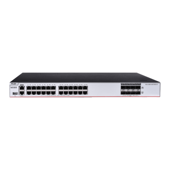
- Page 8 Hardware Installation and Reference Guide Product Overview Front Panel Figure 1-2 Front Panel of RG-CS85-24GT8XS-D Note: 1. System LED 7. Port Status LED 2. Power Supply Status LED (PWR1) 8. 10GE SFP+ Port 3. Power Supply Status LED (PWR2) 9. USB Port 4.
- Page 9 Hardware Installation and Reference Guide Product Overview Note: The product information label is on the bottom of the switch. Power Supply RG-CS85-24GT8XS-D supports 2 power supply modules. Dual-power input: The switch can be powered by one power supply module, or two power supply modules. When both modules are working, the switch is working in power redundancy mode.
- Page 10 Hardware Installation and Reference Guide Product Overview Panel Identification Status Meaning Blinking green Initialization is in progress. Continuous blinking (3 Hz) indicates a fault. It is used for on-site positioning of the device, Blinking green (10 and allows operation and maintenance personnel to perform remote power on and off control.
- Page 11 SFP+ interface SFP module, SFP BIDI module SFP+ module, SFP+ cable, SFP+ BIDI module SFP Module Type See Appendix B. The module types may update without prior notification. Please contact Ruijie Networks for details. Expansion 1 slot Module Slot Supported module: CM85-4XS2CQ ...
- Page 12 Hardware Installation and Reference Guide Product Overview Power < 70 W (without expansion module) Consumption < 95 W (with expansion module) Operating temperature: 0º C to 45º C (32° F to 113° F) (altitude from 0 m to 1800 m (1.12 miles)) The highest operating temperature decreases by 1º...
- Page 13 Hardware Installation and Reference Guide Product Overview Front Panel Figure 1-7 Front Panel of RG-CS85-48GT4XS-D Note: 1. System Status LED 7. Port Status LED 2. Power Supply Status LED (PWR1) 8. 10GE SFP+ Port 3. Power Supply Status LED (PWR2) 9.
- Page 14 Hardware Installation and Reference Guide Product Overview Note: The product information label is on the bottom of the switch. Power Supply The RG-CS85-48GT4XS-D supports two power supply modules. Dual-power input: The switch can be powered by one power supply module, or two power supply modules. When both modules are working, the switch is working in power redundancy mode.
- Page 15 Hardware Installation and Reference Guide Product Overview Panel Identification Status Meaning Blinking green Initialization is in progress. Continuous blinking (3 Hz) indicates a fault. It is used for on-site positioning of the device, Blinking green and allows operation and maintenance (10Hz) personnel to perform remote power on and off control.
- Page 16 SFP+ interface SFP module, SFP BIDI module SFP+ module, SFP+ cable, SFP+ BIDI module SFP Module Type See Appendix B. The module types may update without prior notification. Please contact Ruijie Networks for details. Expansion 1 slot Module Slot Supported module: CM85-4XS2CQ ...
- Page 17 Hardware Installation and Reference Guide Product Overview Power < 77 W (without expansion module) Consumption < 102 W (with expansion module) Operating temperature: 0º C to 45º C (32° F to 113° F) (altitude from 0 m to 1800 m (1.12 miles)) The highest operating temperature decreases by 1º...
- Page 18 Hardware Installation and Reference Guide Product Overview Front Panel Figure 1-12 Front Panel of RG-CS85-24SFP/8GT8XS-D Note: 1. System Status LED 7. GE SFP Port Status LED 2. Power Supply Status LED (PWR1) 8. GE SFP Port 3. Power Supply Status LED (PWR2) 9.
- Page 19 Hardware Installation and Reference Guide Product Overview Note: The product information label is on the bottom of the switch. Power Supply The RG-CS85-24SFP/8GT8XS-D supports two power supply modules. Dual-power input: The switch can be powered by one power supply module, or two power supply modules. When both two modules are working, the switch is working in power redundancy mode.
- Page 20 Hardware Installation and Reference Guide Product Overview Panel Identification Status Meaning The switch is not powered on. Blinking green Initialization is in progress. Continuous blinking (3 Hz) indicates a fault. It is used for on-site positioning of the device, Blinking green (10 and allows operation and maintenance personnel to perform remote power on and off control.
- Page 21 SFP+ interface SFP module, SFP BIDI module SFP+ module, SFP+ cable, SFP+ BIDI module SFP Module Type See Appendix B. The module types may update without prior notification. Please contact Ruijie Networks for details. Power Supply 2 slots Module Slot ...
- Page 22 Hardware Installation and Reference Guide Product Overview Rated current per input: 8 A RG-PA1000I-P-F AC input: Rated voltage: 200 V AC to 240 V AC Maximum voltage: 176 V AC to 264 V AC Frequency: 50/60 Hz Rated current per input: 8 A 10GBase-R Capable SFP+ Port 1000Base-X Capable...
- Page 23 Hardware Installation and Reference Guide Product Overview EMI Certification GB/T 9254.1 Safety Regulation GB 4943.1 Compliance Dimensions 442 mm x 420 mm x 43.6 mm (17.40 in. x 16.54 in. x 1.72 in.) (W x D x H) Weight 5.7 kg (12.57 lbs.) In a domestic environment, this product may cause radio interference.
- Page 24 Hardware Installation and Reference Guide Product Overview Rear Panel Figure 1-18 Rear Panel of RG-CS85-48GT4XS-HPD Note: Grounding Lug 5. Power Supply Module Slot 1 (A filler panel is required Filler Panel if the slot is vacant.) Fan Module 1 6. Power Supply Module Slot 2 (A filler panel is required Fan Module 2 if the slot is vacant.) Product Information Label...
- Page 25 Hardware Installation and Reference Guide Product Overview Panel Identification Status Meaning The switch is not powered on. Blinking green Initialization is in progress. Continuous blinking (3 Hz) indicates a fault. It is used for on-site positioning of the device, Blinking green (10 and allows operation and maintenance personnel to perform remote power on and off control.
- Page 26 Hardware Installation and Reference Guide Product Overview Panel Identification Status Meaning The fan module is in place and functioning Solid green properly 1. A fan module is faulty. Fan status LED 2. The module type is not compatible with the Solid red system.
- Page 27 Hardware Installation and Reference Guide Product Overview See Appendix B. The module types may update without prior notification. Please contact Ruijie Networks for details. Power Supply 2 slots Module Slot Fan Module Slot 3 slots 1 slot...
- Page 28 Hardware Installation and Reference Guide Product Overview Storage -40º C to 70º C (-40º F to 158º F) Temperature Operating 10% to 90% RH (non-condensing) Humidity Operating Altitude 0 to 5000 m (3.11 miles) Storage Humidity 5% to 95% RH (non-condensing) Fan speed control Fan fault alarming Temperature...
- Page 29 Hardware Installation and Reference Guide Product Overview Note: 1. System Status LED 7. Console Port 2. MGMT Port Status LED 8. MGMT Port 3. Power Supply Status LED (PWR1) 9. GE SFP Port 4. Power Supply Status LED (PWR2) 10. GE SFP Port Status LED 5.
- Page 30 Hardware Installation and Reference Guide Product Overview The switch can be powered on by either one power supply module or dual power supply modules. If both power supply modules are used, the switch works in the power redundancy mode. Heat Dissipation The RG-CS85-48SFP4XS-D adopts front-to-back airflow for heat dissipation, thereby ensuring the normal function of the device in the specified environment.
- Page 31 SFP+ module, SFP+ AOC cable, SFP+ BIDI module QSFP+ module, QSFP+ AOC cable QSFP28 module, QSFP28 AOC cable SFP Module Type See Appendix B. The module types may update without prior notification. Please contact Ruijie Networks for details. 10GBase-R Capable SFP+ Port 1000Base-X Capable...
- Page 32 Hardware Installation and Reference Guide Product Overview The 100G can be split into 4*25G mode and the 40G can be split into 4*10G mode. Power < 22 W Consumption Operating temperature: 0º C to 45º C (32° F to 113° F) at a height below 1800 m (1.12 miles) above the sea level.
-
Page 33: Power Supply Modules
Hardware Installation and Reference Guide Product Overview Note: 1. System Status LED 3. GE SFP+ Port Status LED 2. GE SFP+ Port 4. QSFP28 Port Panel Identification Status Meaning The switch is not powered on. Blinking green Initialization is in progress. Continuous blinking (3 Hz) indicates a fault. - Page 34 Hardware Installation and Reference Guide Product Overview RG-PA150I-F, RG-PA150IB-F Power Model RG-CS85-48GT4XS-D Device Model RG-CS85-24GT8XS-D RG-CS85-24SFP/8GT8XS-D/RG-CS85-48SFP4XS-D AC input: 100 V AC to 240 V AC 50/60 Hz Rated Voltage HVDC input: 240 V DC AC input: 90 V AC to 264 V AC 47/63 Hz Maximum Voltage HVDC input:...
- Page 35 Hardware Installation and Reference Guide Product Overview Supports to disconnect one redundant power supply module from the outside power Hot Swapping supply system, plug and unplug power supply modules while the device is powered Power Supply Alarm When a power fault occurs, the output status LED turns off. Status Meaning Output Status...
- Page 36 Hardware Installation and Reference Guide Product Overview -40° C to +70° C (-40° F to 158° F) Storage Temperature Relative Operating 5% to 95% RH (non-condensing) Humidity Relative Storage 5% to 95% RH (non-condensing) Humidity Operating Altitude 0 to 5000 m (3.11 miles) When you plug a power cord, install the power cord retainer on the power cord correctly to prevent the cord from loosening.
- Page 37 Hardware Installation and Reference Guide Product Overview RG-PA1000I-P-F Power Model RG-CS85-48GT4XS-HPD Device Model Rated Input Voltage AC Input: 100 V AC to 240 V AC, 50 Hz/60 Hz Range HVDC Input: 240 V DC Maximum Input AC Input: 90 V AC to 264 V AC, 47 Hz/63 Hz Voltage Range HVDC Input: 192 VDC to 288 VDC Maximum...
- Page 38 Hardware Installation and Reference Guide Product Overview Status Meaning The power supply module is not connected with a power cord. A power output error occurs, including fan fault, output Output Status LED short-circuit, output overcurrent protection, output Solid Red overvoltage protection, power supply failure and overheat protection.
-
Page 39: Preparing For Installation
2 Preparing for Installation 2.1 Safety Precautions To avoid personal injury and equipment damage, please carefully read the safety precautions before you install the RG-CS85 series. The following safety precautions may not cover all possible dangers. 2.1.1 General Safety Precautions ... -
Page 40: Installation Environment Requirements
Keep the indoor installation environment clean and dust-free. Maintain appropriate humidity conditions. 2.1.5 Laser Safety Among the modules supported by the RG-CS85 series, here are many transceiver modules that are Class I laser products. Precaution: When a fiber transceiver works, ensure that the port has been connected with a fiber or covered by a dust cap to keep out dust and prevent it from burning your eyes. -
Page 41: Temperature/Humidity Requirements
Chlorine gas (CI 2.2.4 Grounding Requirements A good grounding system is the basis for stable and reliable running of the RG-CS85 series and is indispensable for preventing lightning strikes and interference. Please carefully check the grounding conditions at the installation site... -
Page 42: Lightning Protection Requirements
The lightning protection power strip can be fixed on the cabinet, workbench, or wall in the equipment room by using cable ties and screws. AC power enters the lightening protection power strip and then gets to the switch. The RG-CS85 series switch is delivered without a lightning protection socket. Please prepare a lightning protection socket yourself. - Page 43 List of Tools Phillips screwdriver, flat-head screwdriver, wires, network cables, fastening bolts, Common Tools diagonal pliers, and binding straps Special Tools Anti-static tools Meters Multimeter The RG-CS85 series switch is delivered without a tool kit. Please prepare a tool kit yourself.
-
Page 44: Installing The Switch
Hardware Installation and Reference Guide Installing the Switch 3 Installing the Switch Please ensure that you have carefully read Chapter 2 and make sure that the requirements in Chapter 2 are all met. 3.1 Installation Procedure 3.2 Preparing Before installation, please confirm the following requirements before installation: ... -
Page 45: Mounting The Switch
3.3.1 Mounting the Switch into a Cabinet The RG-CS85 series switches follow the EIA standard dimensions and can be installed in 19-inch cabinet. During the installation, place the front panel on the front part of the bracket. For safety, fasten screws to secure the bracket on the switch. -
Page 46: Mounting The Switch On A Workbench
Installing an CM85 Series Expansion Module Step 1: Take off the filler panel in the expansion module slot on the front panel of a RG-CS85 series switch. Step 2: Take out a new expansion module. Pinch the captive screws on the module. Align the expansion module with the guide rail of the corresponding slot and straightly and slowly insert the module into the chassis along the guide rail until it clicks into place. - Page 47 Hardware Installation and Reference Guide Installing the Switch Insert the expansion module smoothly. Pay attention to the direction of the expansion panel to avoid wrong insertion. Do not hold the PCB edges or crash the components on the PCB. Insert the expansion module into the chassis gently. If it is difficult to push it, pull the expansion module out and check whether it is aligned with the expansion module slot.
- Page 48 Hardware Installation and Reference Guide Installing the Switch Do not hold the edge of the PCB or crash the components on the PCB. Install a filler panel in a vacant slot where an expansion module is removed to ensure normal ventilation and dissipation and avoid dust in the chassis.
-
Page 49: Installing And Removing The Power Supply Module
Hardware Installation and Reference Guide Installing the Switch Remove the fan module straightly and slowly. Install a filler panel in a vacant slot to ensure the normal ventilation and dissipation and avoid the dust in the chassis. 3.6 Installing and Removing the Power Supply Module Wear anti-static gloves before the following operations. - Page 50 Hardware Installation and Reference Guide Installing the Switch Step 1: Press the latch to pull out the power supply module with one hand. Hold the power supply module with another hand. Step 2: Install a filler panel in the vacant slot and store the removed power supply module into its package. Figure 3-8 Removing a Power Supply Module Remove the power supply module straightly and slowly.
- Page 51 Hardware Installation and Reference Guide Installing the Switch Slide the module into the slot. Verify that the power supply module is in the correct orientation. If you find it difficult to fully insert the module, pull the module out, align it to the guide rails and slide it into the slot again.
-
Page 52: Connecting The External Interface Cables
Hardware Installation and Reference Guide Installing the Switch Precautions The cross-sectional area of the ground cable should be determined according to the possible maximum current. Cables with good conductor should be used. Do not use bare wire. To ensure human safety and device security, the switch must be properly grounded. -
Page 53: Verifying Installation
Hardware Installation and Reference Guide Installing the Switch On the both sides of the chassis, fasten the fibers and twisted pairs to the cabinet cable management ring or cabling chute. For the power cables, you should bundle them closely along the chassis downward in a straight line wherever possible. 3.10 Verifying Installation Before verifying the installation, cut off the power supply to avoid any personal injury or damage to the component due to connection errors. -
Page 54: Setting Up Configuration Environment
Connect the PC to the management port of the switch through a network cable, as shown in Figure 4-1. Figure 4-1 Configuration Environment Connecting the Console Cable The RG-CS85 series switches adopt console cable connecting: Plug the DB-9 head of the console cable into the network port of the PC. - Page 55 Hardware Installation and Reference Guide Verifying Operating Status In the Connectivity Note window, enter the name of the new connection and click OK. A window appears as shown in Figure 4-3. In the Connect Using field, select the serial port you want to use. Figure 4-3 After selecting the serial port, click OK.
- Page 56 Hardware Installation and Reference Guide Verifying Operating Status After setting the serial port parameters, click OK. The Hyperterminal window appears. 4.2 Checking Environment before/after Power-on Checking Environment before Power-on Check whether the switch is properly grounded. Check whether the power cord is properly connected. ...
-
Page 57: Monitoring And Maintenance
Working status of fan and power supply Temperature status For the monitoring commands, refer to RG-CS85 Series Switch RGOS Configuration Guide. 5.2 Maintenance Ventilation System Maintenance The fan module responsible for heat dissipation is equipped with the fault monitoring signal. When the fan module is faulty, an alarm will occur. - Page 58 Throwing the battery into a fire or oven, or mechanically crushing or cutting it may cause the battery to explode. Replacing Fuses To replace fuses, please contact technical support personnel Ruijie Networks. The technical support personnel will select fuses of the same specifications for replacement.
-
Page 59: General Troubleshooting Procedure
The system login password of the switch is forgotten or lost, and so it is not possible to configure the data. [Troubleshooting] Please contact Ruijie Customer Service Department for technical support. Fault 2: The AC power supply module does not work. - Page 60 Check whether the configuration of the serial port on the hyper terminal is the same as that described in RG-CS85 Series Switch RGOS Configuration Guide. If not, modify the serial port configuration parameters. If there is still no serial port printed information, please contact Ruijie Customer Service Department for technical support.
- Page 61 Hardware Installation and Reference Guide Troubleshooting Check whether the optical module wavelengths of the two sides are consistent. For example, an optical module of 1310 nm wavelength cannot be connected to an optical module of 1550 nm wavelength. Check whether the distance between the two sides exceeds the length indicated on the optical module.
-
Page 62: Appendix A Connectors And Media
Hardware Installation and Reference Guide Appendix A Connectors and Media Appendix A Connectors and Media 1000BASE-T/100BASE-TX/10BASE-T Port The 1000BASE-T/100BASE-TX/10BASE-T is a port that supports adaptation of three rates, and automatic MDI/MDIX Crossover at these three rates. The 1000BASE-T complies with IEEE 802.3ab, and uses the cable of 100-ohm Category-5 or Supper Category-5 UTP or STP, which can be up to 100 m (328 feet). - Page 63 Hardware Installation and Reference Guide Appendix A Connectors and Media Optical Fiber Connection For the optical fiber ports, select single-mode or multiple-mode optical fibers for connection according to the fiber module connected. The connection schematic diagram is shown in Figure A-4: Figure A-4 Schematic Diagram for optical fiber connection...
-
Page 64: Appendix B 10G Sfp Modules Specifications
Appendix B 10G SFP Modules Specifications Appendix B 10G SFP Modules Specifications Ruijie Networks provides various Gigabit SFP (Mini-GBIC modules), and 10G SFP+ transceivers for interfaces of modules on the switch. You can select the most suitable SFP transceivers as needed. - Page 65 Hardware Installation and Reference Guide Appendix B 10G SFP Modules Specifications GE-SFP-LX-SM1310 9/125 10 km MINI-GBIC-LH40-SM1310 9/125 40 km GE-SFP-SX-SM1310-BIDI 50/125 500m GE-SFP-SX-SM1550-BIDI 50/125 500m GE-SFP-LX20-SM1310-BIDI 9/125 20 km GE-SFP-LX20-SM1550-BIDI 9/125 20 km GE-SFP-LH40-SM1310-BIDI 9/125 40 km GE-SFP-LH40-SM1550-BIDI 9/125 40 km MINI-GBIC-ZX50-SM1550 9/125 50 km...
- Page 66 Hardware Installation and Reference Guide Appendix B 10G SFP Modules Specifications Wavelength Transmit (dBm) Receive (dBm) Model Fiber Type (nm) (Yes/No) XG-SFP-SR-MM850 -7.5 XG-SFP-SR-SM1270- 1270 BIDI XG-SFP-SR-SM1330- 1270 BIDI XG-SFP-LR-SM1270- 1270 -6.5 -14.4 BIDI XG-SFP-LR-SM1330- 1330 -6.5 -14.4 BIDI XG-SFP-LR-SM1310 1310 -8.2 -10.3...
- Page 67 Hardware Installation and Reference Guide For XG-SFP-ER-SM1550 and XG-SFP-ZR-SM1550, do not use short-distant fibers in case of transceiver overload. If the light power received equals or exceeds -1dBm, add the optical attenuators to adjust the power as less than - 1dBm.
-
Page 68: Appendix C Lightning Protection
Hardware Installation and Reference Guide Appendix C Lightning Protection Appendix C Lightning Protection Installing AC Power Arrester (Lightning Protection Power Strip) The AC power port must be connected to an external lightning protection power strip to prevent the switch from being struck by lightning when the AC power cord is introduced from the outdoor and directly connected to the power port of the switch. - Page 69 Hardware Installation and Reference Guide Appendix C Lightning Protection Please connect an Ethernet port arrester to the switch to prevent the damage by lightning before connecting an outdoor network cable to the switch. Tools: Phillips screwdrivers or flat-head screwdriver, multimeter, and diagonal pliers Installation Steps: ...
-
Page 70: Appendix D Cabling
Hardware Installation and Reference Guide Appendix D Cabling Appendix D Cabling When the RG-CS85 switch is installed in a standard 19-inch cabinet, secure the cables around the cable management brackets. Top cabling or bottom cabling is adopted according to the actual situation in the equipment room. All transferred cable connectors should be placed at the bottom of the cabinet in an orderly manner instead of outside the cabinet that is easy to touch. - Page 71 Hardware Installation and Reference Guide Appendix D Cabling Cables of different types (such as power cords, signal cables, and ground cables) should be separated in cabling and bundling. Mixed bundling is disallowed. When they are close to each other, it is recommended to adopt crossover cabling.
- Page 72 Hardware Installation and Reference Guide Appendix D Cabling Cables not to be assembled or remaining parts of cables should be folded and placed in a proper position of the cabinet or cable trough. The proper position refers to a position that does not affect device running or damage the switch or cable.
- Page 73 Hardware Installation and Reference Guide Appendix D Cabling Power cables of the same type and in the same cabling direction should be bundled up into cable bunches, with cables in cable bunches clean and straight. Bundle up cables by using cable ties based on the following table. Cable Bunch Diameter Distance between Every Binding Spot 10 mm (0.39 in.)
-
Page 74: Appendix E Site Selection
Hardware Installation and Reference Guide Appendix E Site Selection Appendix E Site Selection The equipment room should be at least 5 km away from heavy pollution sources, such as the smelter works, coal mine, and thermal power plant. The equipment room should be at least 3.7 km away from medium pollution sources, such as the chemical factory, rubber factory, and electroplating factory.
Need help?
Do you have a question about the RG-CS85 Series and is the answer not in the manual?
Questions and answers