
Related Manuals for Ruijie RG-S6150-X Series


Summary of Contents for Ruijie RG-S6150-X Series
- Page 1 Ruijie RG-S6150-X Series Switches Hardware Installation and Reference Guide Document Version: V1.01 Date: 2022.6.9 Copyright © 2022 Ruijie Networks...
- Page 2 All rights are reserved in this document and this statement. Any reproduction, excerption, backup, modification, transmission, translation or commercial use of this document or any portion of this document, in any form or by any means, without the prior written consent of Ruijie Networks is prohibited.
- Page 3 Preface Intended Audience This document is intended for: Network engineers Technical support and servicing engineers Network administrators Technical Support Ruijie Networks Website: https://www.ruijienetworks.com/ Technical Support Website: https://ruijienetworks.com/support Case Portal: https://caseportal.ruijienetworks.com Community: https://community.ruijienetworks.com ...
- Page 4 Warning An alert that calls attention to important rules and information that if not understood or followed can result in data loss or equipment damage. Caution An alert that calls attention to essential information that if not understood or followed can result in function failure or performance degradation.
-
Page 5: Table Of Contents
Product Overview Product Overview RG-S6150-X series switches are new-generation Layer-3 switches released by Ruijie Networks, providing high performance, consolidated security and multiple services. The switches are mainly applied to the convergence layer of campus networks to provide line-rate switching and complete QoS policies, prioritizing some traffic over others to ensure important data transmission without latency. - Page 6 Rated current: 3.5 A to 7.2 A Power Consumption Less than 300 W Optical Module Refer to Appendix 7.2 Note The supported modules update at any time, contact Ruijie Networks for details. Temperature Warning Support temperature warning and over-temperature protection. EMC Certification GB/T 9254.1-2021 Safety Regulation GB 4943.1-2011...
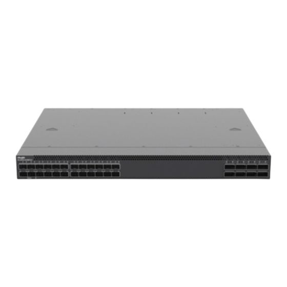
- Page 7 Hardware Installation and Reference Guide Product Overview Note The 25G/100G Ethernet port of the RG-S6150-48VS8CQ-X switch does not support direct attach copper (DAC). The 48VS port license supports 25G port and does not support FEC-RS. Product Appearance The hardware of the RG-S6150-48VS8CQ-X includes the chassis, the power supply system and the heat dissipation system.
- Page 8 Hardware Installation and Reference Guide Product Overview Back Panel Figure 1-3 Back Panel of the RG-S6150-48VS8CQ-X Power Module Slot Console Port Fan Module Slot USB 2.0 Port System Status LED Assess Tag Locator LED Grounding Stud MGMT Port Asset Tag The asset tag is at the bottom right corner of the switch back panel.
- Page 9 Hardware Installation and Reference Guide Product Overview The RG-S6150-48VS8CQ-X switch supports debugging, configuration, maintenance, management and host software uploading of Console ports. Console port: Use RS-232 interface electrical level and standard RJ45 connector. This interface is connected with the serial port of terminal PC to perform system debugging, configuration, maintenance, management, and host software uploading.
- Page 10 Hardware Installation and Reference Guide Product Overview Blinking The port is transmitting or receiving data. SFP28 Port LED 1F-48F The port is not connected. Solid green The port is connected at 1/10/25 Gbps. Blinking green The port is transmitting or receiving data at 1/10/25 Gbps.
-
Page 11: Table
Rated current: 3.5 A to 7.2 A Power Consumption Less than 300 W Optical Module Refer to Appendix 7.2 Note The supported modules update at any time, contact Ruijie Networks for details. Temperature Warning Support temperature warning and over-temperature protection. EMC Certification GB 9254-2008... - Page 12 Hardware Installation and Reference Guide Product Overview Safety Regulation GB 4943.1-2011 Compliance Working Temperature 0° C to 45° C (32° F to 113° F) –40° C to 70° C (–40° F to 158° F) Storage Temperature Working Humidity 10% to 90% RH (non-condensing) Weight Net weight: 10 kg (20.05 lbs., with 4 fan modules and 2 power modules) Dimensions...
- Page 13 Hardware Installation and Reference Guide Product Overview Figure 1-7 Front Panel of the RG-S6150-24VS8CQ-X System Status LED SFP28 Port LED Locator LED QSFP28 Port SFP28 Port QSFP28 Port LED Note The RG-S6150-24VS8CQ-X supports 100GE QSFP28 module, 25GE SFP28 module, 10GE SFP+ module and GE SFP+ module.
- Page 14 Hardware Installation and Reference Guide Product Overview Figure 1-9 Asset Tag of the RG-S6150-24VS8CQ-X External Ports The RG-S6150-24VS8CQ-X provides the following ports: Universal serial bus (USB) port: This port can connect with USB memory to save logs, host versions, warnings and other diagnostic messages.
- Page 15 Hardware Installation and Reference Guide Product Overview System Status LED Status The system is not powered up. (Front panel/Back Solid red One of the modules of the system fails. panel) There are less than 3 fans. The internal or partial temperature exceeds the warning working temperature, and the switching service resets.
- Page 16 1.3.1 RG-PA550I II-F Power Supply Module The RG-S6150-X series switches support the RG-PA550I II-F power supply module. The smart power supply module supports power management, and the switch can read input power, input current, and temperature in real time. The power supply module supports hot swapping.
- Page 17 Hardware Installation and Reference Guide Product Overview Table 1-6 Technical Specifications Input Rated AC input: 100 V AC to 240 V AC; 50/60 Hz Voltage HVDC input: 240 V DC Range Maximum AC input: 90 V AC to 264 V AC; 47/63Hz Input Voltage HVDC input: 192 V DC to 288 V DC Range...
- Page 18 Hardware Installation and Reference Guide Preparing for Installation Preparing for Installation Safety Precautions Note To avoid body injury and device damage, please carefully read the safety precautions before you install the RG -S6150-X series switches. The following safety precautions do not cover all possible dangers. 2.1.1 General Safety Precautions ...
- Page 19 Do not stare at any fiber port under any circumstances, as this may cause permanent damage to your eyes. Installation Environment Requirements Install the RG-S6150-X series switches indoors. To ensure the normal operation and prolonged service life of the device, the installation site must meet the following requirements.
-
Page 20: Rg-S6150-48Vs8Cq-X
2.2.3 Temperature and Humidity Requirements To ensure the normal operation and prolonged service life of the RG-S6150-X series switches, maintain an appropriate temperature and humidity in the equipment room. The equipment room with too high or too low temperature and humidity for a long period of time may damage the equipment. -
Page 21: Table
2.2.5 Grounding Requirements A good grounding system is the basis for the stable and reliable operation of the RG-S6150-X series switches. It is the key to prevent lightning stroke and resist interference. Please carefully check the grounding conditions on the installation site according to the grounding requirements, and perform grounding properly as needed. - Page 22 Hardware Installation and Reference Guide Preparing for Installation Note For lightning protection, refer to Appendix 7.3. EMC Grounding Grounding required for electromagnetic compatibility includes shielded grounding, filter grounding, noise and interference suppression, and level reference, which contribute to the overall grounding requirements. The grounding resistance should be smaller than 1 ohm.
- Page 23 Hardware Installation and Reference Guide Preparing for Installation Tools Table 2-4 Tools Phillips screwdriver, related Ethernet and fiber-optic cables, bolts, diagonal pliers, Common Tools cable ties Antistatic gloves, wire stripper, crimping pliers, crystal connector crimping pliers, and Special Tools wire cutter Cleaning Tools Dust-free paper, fiber end-face microscope Meters...
- Page 24 Hardware Installation and Reference Guide Installing the Switch Installing the Switch RG-S6150-X series switches must be installed indoors. Note Please ensure that you have carefully read Chapter 2 and make sure that the requirements in Chapter 2 are all met.
- Page 25 Hardware Installation and Reference Guide Installing the Switch Prepare for installation Prepare for installation Install the cabinet Mount the switch into the cabinet Ground the switch Connect the power supply Install the modules Connect the cables Bundle the cables Verify the installation Before You Begin Carefully plan and arrange the installation position, networking mode, power supply, and cabling before installation.
- Page 26 Hardware Installation and Reference Guide Installing the Switch The power supply and required current are available at the installation site. The Ethernet cables have already been deployed at the installation site. Mounting the Cabinet Precautions When mounting the cabinet, please note the followings: ...
- Page 27 Mounting the Switch in a Rack All models of the RG-S6150-X series switches can be installed in a 19-inch EIA rack. Mount the switch in the rack with the front panel face forward. You are advised to use a tray to install the switch and secure the tray on the bracket, or use the rear bracket provided with the switches.
- Page 28 Hardware Installation and Reference Guide Installing the Switch Use the provided screws to attach a rack- Attach the left and right guide rails to the mount guide to each side of the switch. rack. Tighten the screws to secure the brackets Slide the rack-mount guides onto the guide on the rack.
- Page 29 Hardware Installation and Reference Guide Installing the Switch Figure 3-3 Mounting the Switch on a Workbench Attach the four rubber pads to Place the switch on the workbench. the four corners on the switch bottom. Installing and Removing a Fan Module Precautions ...
- Page 30 Hardware Installation and Reference Guide Installing the Switch Caution Slide the fan module into the slot. Verify that the fan module is in the correct orientation. If you find the direction is incorrect when inserting the module, pull the fan module out, and slide it into the slot again.
- Page 31 Hardware Installation and Reference Guide Installing the Switch Installing a Power Supply Module (1) Remove the new power supply module from its packing materials and make sure the input method and specifications meet requirements. (2) Remove the filler panel covering the slot. Keep the module nameplate face upward. Grasp the handle with one hand and place your other hand under the power supply module to support its weight.
- Page 32 Hardware Installation and Reference Guide Installing the Switch Figure 3-7 Retainer Strip, Retainer Clamp and Latches Latch B Latch A (2) Thread the retainer strip through the hole at the bottom of the clamp and lock it into place. If you want to remove the strip, press the latch A and pull the strip out.
- Page 33 Hardware Installation and Reference Guide Installing the Switch Figure 3-9 (b) Installing the Retainer Strip Removing a Power Supply Module (6) Press the latch on the module and grasp the handle with one hand to pull a part of the module. Place your other hand under the module to support its weight.
- Page 34 Hardware Installation and Reference Guide Installing the Switch Connecting a Grounding Cable Connect the PGND to the grounding lug of the cabinet and then connect the grounding lug to the grounding bar of the equipment room. Precautions The sectional area of the grounding wire should be determined according to the possible maximum current. Cables with good conductor should be used.
- Page 35 Hardware Installation and Reference Guide Installing the Switch Simple Connection Steps (1) Connect one end of the RJ45 connector to the Ethernet MGMT interface of the device board, and the other end to the NM or a control terminal (2) Insert the single-mode or multi-mode fiber into the appropriate interface according to the identification on the panel of the line card.
- Page 36 Hardware Installation and Reference Guide Installing the Switch Checking Power Supply Verify that the power cord is properly connected and compliant with safety requirements. Note Please turn off the power to avoid personal injury and damage to components before checking the power supply.
- Page 37 Hardware Installation and Reference Guide Verifying Operating Status Verifying Operating Status Establishing the Configuration Environment Establishing the Configuration Environment Connect the PC to the console port of the switch through the console cable, as shown in Figure 4-1. Figure 4-1 Schematic diagram of the configuration environment Connecting the Console Cable (1) Connect one end of the DB-9 jack of the console cable to the serial port of the PC.
- Page 38 Hardware Installation and Reference Guide Verifying Operating Status Figure 4-2 Schematic diagram of the configuration environment (3) Enter the name of the new connection and click OK. A window appears as shown in Figure 4-3. In the column of Connect Using field, select the serial port you want to use. Figure 4-3 Schematic diagram of the configuration environment (4) After the serial port is selected, please click OK.
- Page 39 Hardware Installation and Reference Guide Verifying Operating Status Figure 4-4 Schematic diagram of the configuration environment (5) After the serial port parameters are set, click OK to enter hyper terminal window. Powering on the Switch Checking before Power-on Check if the switch is fully grounded. ...
- Page 40 Working status of fan and power supply Temperature status Note For the monitoring commands, refer to RG-S6150-X Series Switches RGOS Configuration Guide. Hardware Maintenance Expansion Module Maintenance To replace a board, do replacement according to the instructions provided in Sections of Installing Modules and Removing Modules.
- Page 41 Throwing the battery into a fire or oven, or mechanically crushing or cutting it may cause the battery to explode. Replacing Fuses Please contact the technical support representatives of Ruijie Networks for replacing fuses. Technical staff of Ruijie Networks will replace the fuse of the same model.
- Page 42 Check the installation of the power supply module Check the connector of each module Check the installation of other modules Check the LEDs on the device Check serial port connection and parameters Check the cable connection Contact Technical Support of Ruijie Networks...
- Page 43 [Troubleshooting] Such a problem is related to the settings of the serial port. Check if the settings of such parameters as the baud rate match those in RG-S6150-X Series Switches RGOS Configuration Guide.
- Page 44 If the newly-inserted module still cannot be powered on even though the checking is ok, please contact Ruijie Customer Service Department for technical support. Fault 7: The link cannot be set up between fiber ports.
- Page 45 Hardware Installation and Reference Guide Appendix Appendix Connectors and Connection Media 10GBASE-T/5GBASE-T/2.5GBASE-T/1000BASE-T/100BASE-TX Port 10GBASE-T/5GBASE-T/2.5GBASE-T/1000BASE-T/100BASE-TX is a port that supports self-adaptation of five rates, and automatic MDI/MDIX Crossover at these five rates. 10GBASE-T 10GBASE-T complies with IEEE 802.3an standard, and the supported cables and cabling distances are listed in the following table.
- Page 46 Hardware Installation and Reference Guide Appendix It is recommended to use CAT6A shielded wire or wires with higher specifications for the cabling of the new equipment room. CAT6A or CAT7 shielded wire can maximize the avoidance of external crosstalks. Note the cabling system and the overall grounding when shielded wire is used.
- Page 47 Hardware Installation and Reference Guide Appendix Note 2.5GBASE-T is applied to transmit CAT5e UTP. The maximum transmission distance will be less than 50 m (164.04 ft) when CAT5e UTP unshielded wire is exposed in severe condition and influenced by external crosstalk. If CAT5e UTP wire is applied in the cabling of the equipment room, the cabling must meet TIA TSB-5021 requirements.
- Page 48 Hardware Installation and Reference Guide Appendix Input Receive Data- Output Transmit Data- Output Transmit Data+ Input Receive Data+ Output Transmit Data- Input Receive Data- 4, 5, 7, 8 Not Used Not Used Figure 7-2 shows the feasible connections of the straight-through and crossover twisted pairs of the 100BASE- Figure 7-2 Connection of the twisted pairs of the 100BASE-TX Fiber Connection For the fiber ports, select single-mode or multiple-mode fibers for connection according to the fiber module...
- Page 49 Hardware Installation and Reference Guide Appendix Mini-GBIC, 10G, 25G, 40G and 100G Module We provide Gigabit SFP modules (Mini-GBIC modules), 10G SFP+ modules, 40G QSFP+ modules, 100G QSFP28 modules and AOC modules according to the port types. You can select modules to suit your specific needs.
- Page 50 Hardware Installation and Reference Guide Appendix GE-SFP-LH40- 1550TX/1310RX SM1550-BIDI SFP-S4- 1310 -9.5 R1000P1 V1 Note According to the specifications of intensity of received light, install an on-line optical attenuator to avoid overload when using short fiber-optic cables for following modules: GE-SFP-LH40-SM1310-BIDI, GE-SFP-LH40- SM1550-BIDI, MINI-GBIC-LH40-SM1310, MINI-GBIC-ZX50-SM1550, MINI-GBIC-ZX80-SM1550, MINI-GBIC- ZX100-SM1550, SDH155-SFP-LH40-SM1310, SDH155-SFP-LH80-SM1550.
- Page 51 Hardware Installation and Reference Guide Appendix GE-SFP-LX20- 20 km 9/125 SM1310-BIDI GE-SFP-LX20- 20 km 9/125 SM1550-BIDI GE-SFP-LH40- 40 km 9/125 SM1310-BIDI 40 km GE-SFP-LH40- 9/125 SM1550-BIDI 1310 10 km SFP-S4-R1000P1 9/125 Table 7-5 Pairing Models of BIDI SFP Modules Rate/Distance Paring Models GE-SFP-LX20-SM1310-BIDI 1000 Mbps/20 km...
- Page 52 Hardware Installation and Reference Guide Appendix 1550 40 km -4.7 -11.3 SFP- connector) SM155 1550 80 km SFP- connector) SM155 Table 7-7 Modules not Supporting 10G SFP+ Model Wavelength Optical Core Modular Intensity of Intensity of Fiber Size Bandwidth Cabling Transmitted Received (nm)
- Page 53 Hardware Installation and Reference Guide Appendix (MPO 4700 150 m connec (OM4) tor) 40G-QSFP- 840, 2000 300 m -7.6 to 2.3 -9.9 to 2.4 LSR-MM850 (MPO (OM3) connec 4700 400 m tor) (OM4) 40G-QSFP- 1264.5, 10 km -7.0 to 2.3 -13.7 to 2.3 LR4-SM1310 1277.5,...
- Page 54 Hardware Installation and Reference Guide Appendix (OM3) (MPO 100G- connect QSFP- 4700 100 m (OM4) MM850 100G- 1294.53, 10 km -4.3 to 4.5 -10.6 to 4.5 QSFP- 1296.59 LR4- 1299.02, SM1310 1301.09 1303.54, 1305.63 1308.09, 1310.19 100G- 1264.5, 2 km -6.5 to 2.5 -11.5 to 2.5 QSFP-...
- Page 55 Hardware Installation and Reference Guide Appendix Lightning Protection Installing AC Power Arrester (lightning protection cable row) The external lightning protection cable row should be used on the AC power port to prevent the switch from being struck by lightning when the AC power cable is introduced from the outdoor and directly connected to the power port of the switch.
- Page 56 Hardware Installation and Reference Guide Appendix on the right, the polarity of the arrester power cable shall be reversed by the power arrester; if the LED is still Red, it is confirmed that the arrester PE terminal has not been grounded. Installing the Ethernet Port Arrester During the switch usage, the Ethernet port arrester should be connected to the switch to prevent the switch damage by lightning before the outdoor network cable connects to the switch.
- Page 57 Hardware Installation and Reference Guide Appendix Reversed installation direction of the arrester. Connect the external Ethernet cable to the IN end and connect the Ethernet port of the switch to the OUT end. Poor grounding of the arrester. The ground cable of the arrester should be as short as possible to ensure that it is in good contact with the ground terminal of the switch.
- Page 58 Hardware Installation and Reference Guide Appendix Cables of different types (such as power cords, signal cables, and grounding cables) should be separated in cabling and bundling and no mixed bundling is allowed. When they are close, crossover cabling can be adopted.
- Page 59 Hardware Installation and Reference Guide Appendix Figure 7-8 Bundling up cables (3) Cables not to be assembled or remaining parts of cables should be folded and placed in a proper position of the cabinet or cabling slot. The proper position indicates a position that will not affect device running or cause device damage or cable damage during commissioning.
- Page 60 Hardware Installation and Reference Guide Appendix The hard power cable should be fastened at the terminal connection area to prevent stress on terminal connection and cable. Do not use self-tapping screws to fasten terminals. Power cables of the same type and in the same cabling direction should be bundled up into cable bunches, with cables in cable bunches clean and straight.
- Page 61 Hardware Installation and Reference Guide Appendix Site Selection The equipment room should be at least 5 km (3.11 miles) 5away from heavy pollution sources, such as the smelter works, coal mine, and thermal power plant. The equipment room should be at least 3.7 km (2.30 miles) away from medium pollution sources, such as the chemical factory, rubber factory, and electroplating factory.
Need help?
Do you have a question about the RG-S6150-X Series and is the answer not in the manual?
Questions and answers