
Related Manuals for Ruijie RG-CS86 Series


Summary of Contents for Ruijie RG-CS86 Series
- Page 1 Ruijie RG-CS86 Series Switches Hardware Installation and Reference Guide Document Version: V1.1 Date: 2023.07.13 Copyright © 2023 Ruijie Networks...
- Page 2 Due to product version upgrades or other reasons, the content of this document will be updated from time to time. Ruijie Networks reserves the right to modify the content of the document without any notice or prompt. This manual is for reference only. Ruijie Networks endeavors to ensure content accuracy and will not shoulder...
- Page 3 Ruijie RG-CS86 Series Switches Hardware Installation and Reference Guide (V1.1) Preface Intended Audience This document is intended for: Network engineers Technical support and servicing engineers Network administrators Technical Support Ruijie Networks website: https://www.ruijienetworks.com/ Technical support website: https://ruijienetworks.com/support...
- Page 4 Ruijie RG-CS86 Series Switches Hardware Installation and Reference Guide (V1.1) Warning An alert that calls attention to important rules and information that if not understood or followed can result in data loss or equipment damage. Caution An alert that calls attention to essential information that if not understood or followed can result in function failure or performance degradation.
- Page 5 Gbps or 10 Gbps). Operation at mixed rates is not supported. 25GE SFP28 ports of the RG-CS86 series multi-GE switches, when operating at the rate of 25 Gbps, support optical modules, but do not support Direct Attach Copper (DAC) cables. See Appendix B for supported optical module models and specifications.
- Page 6 10GE SFP+ ports of the RG-CS86 series multi-GE switches support 10GBASE-R and 1000BASE-X standards. When operating in 1000BASE-X mode, these ports support auto-negotiation without manually configuring the rate and duplex mode. 40GE QSFP+ ports of the RG-CS86 series multi-GE switches support both 40GE mode and 4x10GE mode. RG-CS86-24MG4VS-UP Specifications...
- Page 7 Ruijie RG-CS86 Series Switches Hardware Installation and Reference Guide (V1.1) Temperature Support temperature alarm and over-temperature protection. Alarm GB/T 9254.1 Class A Certification Safety Regulation GB 4943.1 Compliance Altitude 0-5000 m (0-16404 ft.) 0º C to 45º C (32º F to 113 º F) at a height below 3000 m (9842 ft.) above the sea level...
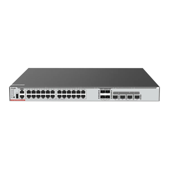
- Page 8 Ruijie RG-CS86 Series Switches Hardware Installation and Reference Guide (V1.1) The front panel of the RG-CS86-24MG4VS-UP Ethernet switch is provided with 24 multi-GE electrical ports (100ME/1GE/2.5GE/5GE), with each port supporting IEEE 802.3bt Type 4 (90 W) PoE, four 25G optical ports, one management Ethernet electrical port (MGMT), one USB port, and one console port (Console).
- Page 9 Ruijie RG-CS86 Series Switches Hardware Installation and Reference Guide (V1.1) Blinking The port is sending and receiving traffic at 100/10 Mbps. yellow No link is established on this port. Solid green A 1 Gbps/2.5 Gbps/5 Gbps link is established on this port.
- Page 10 Ruijie RG-CS86 Series Switches Hardware Installation and Reference Guide (V1.1) Figure 1-1 Appearance of an RG-CS86-24MG4VS-UP Switch Front Panel Figure 1-2 Front Panel of an RG-CS86-24MG4VS-UP Switch Note 1. System status LED 7. Ethernet port for management 2. MGMT interface status LED 8.
- Page 11 Ruijie RG-CS86 Series Switches Hardware Installation and Reference Guide (V1.1) Figure 1-3 Rear Panel of an RG-CS86-24MG4VS-UP Switch Note 1. Grounding stud 2. AC power connector External Ports The RG-CS86-24MG4VS-UP switch provides the following ports: USB port: The USB port is the interface into which you plug your USB storage device for online upgrade or log storage.
- Page 12 Ruijie RG-CS86 Series Switches Hardware Installation and Reference Guide (V1.1) If you want to switch the LED mode, press the button for over two seconds. Heat Dissipation The RG-CS86-24MG4VS-UP switch adopts a left-to-right and front-to-right airflow design to ensure that the switch works properly in the specified environment.
- Page 13 Ruijie RG-CS86 Series Switches Hardware Installation and Reference Guide (V1.1) Quantity: 2 Supported power module model: RG-PA600I-P-F AC Input Rated Voltage Range: 100 V AC to 240 V AC Maximum Voltage Range: 90 V AC to 264 V AC Frequency: 50/60 Hz...
- Page 14 Ruijie RG-CS86 Series Switches Hardware Installation and Reference Guide (V1.1) AC Input: 90 V AC to 176 V AC (excluded) Power supply: two RG-PA600I-P-F power modules PoE available power: 880 W Power supply: two RG-PA1000I-P-F power modules PoE available power: 1420 W...
- Page 15 Ruijie RG-CS86 Series Switches Hardware Installation and Reference Guide (V1.1) On the front panel of the RG-CS86-48MG4VS2QXS-UPD Ethernet switch, there are 48 multi-GE electrical ports (100ME/100ME/1GE/2.5GE/5GE), with the first 24 electrical ports supporting IEEE 802.3bt Type 4 (90 W) PoE, and the last 24 electrical ports supporting IEEE 802.3bt Type 4 (30 W) PoE, four 25GE optical ports, and two 40GE optical ports.
- Page 16 Ruijie RG-CS86 Series Switches Hardware Installation and Reference Guide (V1.1) Note 1. LED mode LED 8. Electrical port LED 2. Fan status LED (FAN) 9. 100ME/1GE/2.5GE/5GE multi-GE electrical ports 3. PWR2 status LED 10. SFP28 port LED 4. PWR1 status LED 11.
- Page 17 Ruijie RG-CS86 Series Switches Hardware Installation and Reference Guide (V1.1) IEEE 802.3bt Type 4 (90W) PoE, and the last 24 ports support IEEE 802.3bt Type 4 (30W) PoE. SFP28 ports: four 25GE/10GE SFP28 ports, supporting 25GE optical module, and 10GE optical module or DAC cable, but not 25GE copper cable.
- Page 18 Ruijie RG-CS86 Series Switches Hardware Installation and Reference Guide (V1.1) One fan module is faulty. Solid red Fan module model is not supported. One fan module is not seated. Solid green The LED indicates the switching status. PoE LED Solid yellow The LED indicates the PoE power supply status.
- Page 19 Ruijie RG-CS86 Series Switches Hardware Installation and Reference Guide (V1.1) The LED Mode button is used to switch the LED mode. The green LED Mode indicator indicates the switching status. Press the LED Mode button, and the LED Mode indicator will turn yellow, indicating the PoE status.
- Page 20 Ruijie RG-CS86 Series Switches Hardware Installation and Reference Guide (V1.1) Supported Fan module model: M2SFAN I-F Quantity: 2 Supported power module model: RG-PA600I-P-F AC Input Rated Voltage Range: 100 V AC to 240 V AC Maximum Voltage Range: 90 V AC to 264 V AC...
- Page 21 Ruijie RG-CS86 Series Switches Hardware Installation and Reference Guide (V1.1) Power supply: two RG-PA600I-P-F power modules PoE available power: 930 W Power supply: two RG-PA1000I-P-F power modules PoE available power: 1470 W PoE Power Four pairs (1-2, 3-6, 4-5 and 7-8 pairs)
- Page 22 Ruijie RG-CS86 Series Switches Hardware Installation and Reference Guide (V1.1) Appearance On the front panel of the RG-CS86-24XMG4XS4VS-UPD Ethernet switch, there are 24 multi-GE electrical ports (100ME/1GE/2.5GE/5GE/10GE), with each electrical port supporting IEEE 802.3bt Type 4 (90 W) PoE, four 10GE optical ports, four 25GE optical ports, one management Ethernet electrical port (MGMT), one USB port, and one console port (Console).
- Page 23 Ruijie RG-CS86 Series Switches Hardware Installation and Reference Guide (V1.1) Note 1. LED mode LED 9. Console port 2. Fan status LED (FAN) 10. Ethernet port for management (MGMT) 3. PWR2 status LED 11. Multi-GE electrical port LED 4. PWR1 status LED 12.
- Page 24 Ruijie RG-CS86 Series Switches Hardware Installation and Reference Guide (V1.1) SFP+ ports: four 10G/1G SFP+ ports, supporting optical modules and DAC cable, and compatible with the 1000BASE-X mode. SFP28 ports: four 25GE/10GE SFP28 ports, supporting 25GE optical module, and 10GE optical module or DAC cable, but not 25GE copper cable.
- Page 25 Ruijie RG-CS86 Series Switches Hardware Installation and Reference Guide (V1.1) No link is is established on this port. Green A 1000 Mbps link is established on this port. The port is sending and receiving traffic at 1000 MGMT Port Blinking green MGMT Mbps.
- Page 26 Ruijie RG-CS86 Series Switches Hardware Installation and Reference Guide (V1.1) Figure 1-12 Airflow Direction Module 1.4.1 RG-PA600I-P-F Power Module RG-CS86-48MG4VS2QXS-UPD and RG-CS86-24XMG4XS4VS-UPD support RG-PA600I-P-F swappable power module. The RG-PA600I-P-F is an AC module (AC/HVDC input and DC output) providing an output voltage of 56 V and an output power of up to 600 W.
- Page 27 Ruijie RG-CS86 Series Switches Hardware Installation and Reference Guide (V1.1) Voltage Range HVDC Input: 192 V DC to 288 V DC Maximum Input Current Output Voltage 56 V Maximum Output 10.72A Current Maximum Output 600 W Power PoE Available PoE available power is subject to the product model (see data sheet for details).
- Page 28 Ruijie RG-CS86 Series Switches Hardware Installation and Reference Guide (V1.1) Alarming When a power fault occurs, the output status LED turns off. LEDs Name Status Description The power module is not connected to a power cord. A power output error occurred,...
- Page 29 Ruijie RG-CS86 Series Switches Hardware Installation and Reference Guide (V1.1) 1000 W (Input Voltage: 176 V AC to 290 V AC or 190 V DC to 290 V DC) Maximum Output Power 930 W (Input Voltage: 90 V AC to 176 V AC, 176 V AC not included) PoE Available PoE available power is subject to the product model (see data sheet for details).
- Page 30 Ruijie RG-CS86 Series Switches Hardware Installation and Reference Guide (V1.1) A power output error occurred, including fan fault, output short-circuit, output Solid red overcurrent protection, output overvoltage protection, power supply failure and overheat protection. Solid green The power module is functioning normally.
- Page 31 Ruijie RG-CS86 Series Switches Hardware Installation and Reference Guide (V1.1) Preparing for Installation Safety Precautions Note To avoid personal injury and device damage, carefully read the safety precautions before you install the device. The following safety precautions may not cover all possible dangers.
- Page 32 Ruijie RG-CS86 Series Switches Hardware Installation and Reference Guide (V1.1) Caution Improper or incorrect electric operations may cause a fire, electric shock, and other accidents, and lead to severe and fatal personal injury and device damage. Direct or indirect contact with high voltage or mains power supply through wet objects may cause fatal dangers.
- Page 33 Ruijie RG-CS86 Series Switches Hardware Installation and Reference Guide (V1.1) 2.1.5 Laser Safety Among the modules supported by the device, many optical modules are Class I laser products. Precautions When an optical transceiver is working, ensure that its port is connected to an optical fiber or covered by a dust cap to keep out dust and prevent it from burning your eyes.
- Page 34 Ruijie RG-CS86 Series Switches Hardware Installation and Reference Guide (V1.1) The table below lists the ambient temperature and humidity requirements of the device. Model Operating Temperature Operating Humidity RG-CS86-24MG4VS-UP 0º C to 45º C (32º F to 113º F) 10% to 90% (non-condensing) RG-CS86-48MG4VS2QXS-UPD 0º...
- Page 35 Ruijie RG-CS86 Series Switches Hardware Installation and Reference Guide (V1.1) 2.2.5 Grounding Requirements A proper grounding system is the basis for stable and reliable operation of the device. It is indispensable for preventing lightning strikes and interference. Carefully check the grounding conditions at the installation site according to the grounding specifications, and complete grounding properly based on the actual situation.
- Page 36 Dust-free paper, fiber end-face microscope Meters Multimeter, bit error rate tester (BERT), optical power meter Note The RG-CS86 series multi-GE switches are delivered without a tool kit. The tool kit is customer-supplied. Unpacking the Switch Package Contents Chassis Kit Switch, yellow and green grounding cable, Quick Start Guide and Package Contents...
- Page 37 Ruijie RG-CS86 Series Switches Hardware Installation and Reference Guide (V1.1) Installing the Switch The RG-CS86 series multi-GE switches must be installed indoors. Note Before installing the device, make sure that you have carefully read and met the requirements specified in Chapter 2.
- Page 38 Ruijie RG-CS86 Series Switches Hardware Installation and Reference Guide (V1.1) The power supply and required current are available in the installation site. The Ethernet cables have been deployed in the installation site. Mounting the Cabinet Precautions When mounting the cabinet, you must pay attention to the following: ...
- Page 39 Installing the Switch on a Rack The RG-CS86 series multi-GE switches meet the EIA standard, and can be installed in a 19-inch rack. During installation, place the device on the rack with the front panel facing forward. RG-CS86-48MG4VS2QXS-UPD and RG-CS86-24XMG4XS4VS-UPD switches are shipped with L brackets and shelf bracket rails.
- Page 40 Ruijie RG-CS86 Series Switches Hardware Installation and Reference Guide (V1.1) Figure 3-1 Mounting on a Rack Mounting on a Workbench In some cases, if a standard 19-inch rack is not available, the switch can be mounted on a clean workbench.
- Page 41 Ruijie RG-CS86 Series Switches Hardware Installation and Reference Guide (V1.1) Figure 3-2 Mounting on a Workbench Installing and Removing a Fan Module Wear an ESD wrist strap before performing the following operation. Installing a Fan Module (1) Remove the fan module from its package.
- Page 42 Ruijie RG-CS86 Series Switches Hardware Installation and Reference Guide (V1.1) (3) Install the blank panel in the empty slot. Put the removed fan module back into its package. Figure 3-4 Removing a Fan Module Caution Make sure that the fan module is pulled out of the slot gently.
- Page 43 Grounding the Switch A Ground cable is installed on the back of RG-CS86 series switch. First connect the Ground cable to the grounding terminal of the cabinet and then connect the grounding terminal to the grounding bar of the equipment room.
- Page 44 Ruijie RG-CS86 Series Switches Hardware Installation and Reference Guide (V1.1) Connecting the External Interface Cables Precautions Correctly distinguish single-mode and multi-mode fibers and ports. Avoid a small bend radius at the connector. Steps (1) Connect the RJ-45 connector of the delivered Ethernet cable to the management port of the switch and the other end to the management terminal.
- Page 45 Ruijie RG-CS86 Series Switches Hardware Installation and Reference Guide (V1.1) Verify that the grounding cables are connected properly and match the requirement. Verify that interface cables are routed indoors. If not, check whether the power supply and interfaces are protected from lightning strikes.
- Page 46 Ruijie RG-CS86 Series Switches Hardware Installation and Reference Guide (V1.1) System Debugging Setting Up the Configuration Environment Setting Up the Environment Connect a PC to the console port of the switch by using an Ethernet cable, as shown in Figure 4-1.
- Page 47 Ruijie RG-CS86 Series Switches Hardware Installation and Reference Guide (V1.1) Figure 4-2 (1) In the Name box, enter the new connection name and click OK. The Connect to dialog will appear. From the Connect Using drop-down list, select the COM1 port to be used.
- Page 48 Ruijie RG-CS86 Series Switches Hardware Installation and Reference Guide (V1.1) Figure 4-4 (3) Click OK. The HyperTerminal window will appear. Powering on the Switch Checking Before Power-On Check that the device is properly grounded. Check that the power module is securely seated.
- Page 49 System temperature Note For the monitoring commands, see the RG-CS86 series Multi-GE Switches Configuration Guide. Hardware Maintenance Maintenance of Expansion Modules If the expansion module needs to be replaced in case of a failure, the operation instructions for installation and removal of the expansion module must be followed for replacing the expansion module.
- Page 50 Ruijie RG-CS86 Series Switches Hardware Installation and Reference Guide (V1.1) Replacing Lithium Battery The device has a built-in lithium battery to maintain the real-time clock without external power. To replace the lithium battery, contact technical support personnel. Risk of fire or explosion or defeat the safeguard of equipment if the battery is replaced by an incorrect type.
- Page 51 Ruijie RG-CS86 Series Switches Hardware Installation and Reference Guide (V1.1) Troubleshooting Troubleshooting Flowchart Abnormal working after installation Check the cabinet installation Check the mounting of the switch in the cabinet Check the power connection Check the installation of the power supply module...
- Page 52 HyperTerminal. Check whether the configuration of the serial port on the HyperTerminal is consistent with that in Configuration Guide. If there is still no output on the serial port, please contact Ruijie technical support. Fault 5: The serial port console output is garbled.
- Page 53 Ruijie RG-CS86 Series Switches Hardware Installation and Reference Guide (V1.1) Verify that the expansion module is inserted in place. If everything is normal, but the new module still cannot be powered on, contact Ruijie Networks Customer Service Department for technical support.
- Page 54 Ruijie RG-CS86 Series Switches Hardware Installation and Reference Guide (V1.1) Appendix A Connectors and Connection Media 10GBASE-T/5GBASE-T/2.5GBASE-T/1000BASE-T/100BASE-TX Port The 10GBASE-T/5GBASE-T/2.5GBASE/1000BASE-T/100BASE-TX port supports five kinds of adaptive speeds and supports the automatic MDI/MDIX crossover function under at these five kinds of speeds.
- Page 55 Ruijie RG-CS86 Series Switches Hardware Installation and Reference Guide (V1.1) If you need to bundle cables, you are advised to tie CAT6A UTP cables every 50 cm to 70 cm (19.69 in. to 27.56 in.), and the CAT6 UTP cables every 160 cm to 180 cm (62.99 in. to 70.87 in.).
- Page 56 Ruijie RG-CS86 Series Switches Hardware Installation and Reference Guide (V1.1) (6) Replace the CAT5e connector with the CAT6 connector. 1000BASE-T Compliant with IEEE 802.3ab, 1000BASE-T requires CAT5, 5E or higher 100-ohm twisted pairs with a maximum distance of 100 meters (328 feet). The 1000BASE-T port requires all four pairs of wires be connected for data transmission.
- Page 57 Ruijie RG-CS86 Series Switches Hardware Installation and Reference Guide (V1.1) Figure A-4 Fiber-Optic Cable Connection - 53 -...
- Page 58 Ruijie RG-CS86 Series Switches Hardware Installation and Reference Guide (V1.1) Appendix B Mini-GBIC, 10GE, 25GE, 40GE and 100GE SFP Modules We provide Gigabit SFP modules (Mini-GBIC modules), 10GE SFP+modules, 40GE QSFP+ modules, 100GE QSFP28 modules and AOC modules according to the SFP port types. You can select the module to suit your specific needs.
- Page 59 Ruijie RG-CS86 Series Switches Hardware Installation and Reference Guide (V1.1) GE-SFP-LH40-SM1550- 1550TX/131 Single BIDI -mode Single SFP-S4-R1000P1 V1 1310 -9.5 -mode Caution According to the received light intensity index, for the following modules, when using short-distance single-mode fiber, an online optical attenuator should be inserted in the link to avoid damage to the optical module.
- Page 60 Ruijie RG-CS86 Series Switches Hardware Installation and Reference Guide (V1.1) GE-SFP-LH40-SM1550-BID Single-mo 9/125 40 km Single-mo SFP-S4-R1000P1 V1 1310 9/125 10 km Pairing of SFP BIDI Optical Modules Rate/Distance Pairing Model GE-SFP-LX20-SM1310-BIDI GE/20 km GE-SFP-LX20-SM1550-BIDI GE-SFP-LH40-SM1310-BIDI GE/40 km GE-SFP-LH40-SM1550-BIDI Caution BIDI optical modules must be used in pairs.
- Page 61 Ruijie RG-CS86 Series Switches Hardware Installation and Reference Guide (V1.1) SR-MM8 mode 26 m fiber 2000 conne 82 m ctor) 66 m Single -mode XG-SFP- fiber LR-SM1 1310 conne ctor) Single -mode XG-SFP- fiber ER-SM1 1550 conne ctor) Single -mode...
- Page 62 Ruijie RG-CS86 Series Switches Hardware Installation and Reference Guide (V1.1) fiber conne ctor) Current models of 10G SFP+ copper cable modules: Copper Suppo Conductor Modul Connect Cable rted Model Diameter Rate (Gbps) e Type or Type Length (AWG) (Yes/N Passiv...
- Page 63 Ruijie RG-CS86 Series Switches Hardware Installation and Reference Guide (V1.1) (μm) (nm) (MHz· k Dista (Yes/No tted d Light Light (dBm) (dBm) 2000 Multi-mo -7.6 to -9.5 to 40G-Q SFP-S (MPO R-MM8 (Per (Per connecto lane) lane) 4700 2000 Multi-mo -7.6 to...
- Page 64 Ruijie RG-CS86 Series Switches Hardware Installation and Reference Guide (V1.1) Intensity Intensity Modular Max. Wavele Support Bandwi Cabli Transmi ngth Size Receive Model Fiber Type tted d Light (MHz· k Dista (μm (nm) (Yes/No Light (dBm) (dBm) 100GB 70 m...
- Page 65 Ruijie RG-CS86 Series Switches Hardware Installation and Reference Guide (V1.1) Appendix C Lightning Protection Installing an AC Power Arrester (Lightning Resistance Socket) When an AC power cord is introduced from outdoors and directly connected to the power port of the switch, the AC power port must be connected to an external lightning protection power strip to protect the switch against lightning strokes.
- Page 66 Ruijie RG-CS86 Series Switches Hardware Installation and Reference Guide (V1.1) If not, the polarity of the arrester power cord should be reversed. In this case, you should open the power arrester and rectify the polarity of the connection. If the indicator is still red, the arrester's PE terminal is not grounded.
- Page 67 Ruijie RG-CS86 Series Switches Hardware Installation and Reference Guide (V1.1) Note The Ethernet port arrester is only for the 10/100 Mbps copper ports with an RJ-45 connector. The Ethernet port arrester is not delivered with the switch. Please purchase it based on actual requirements.
- Page 68 Ruijie RG-CS86 Series Switches Hardware Installation and Reference Guide (V1.1) Appendix D Cabling Recommendations When the switch is installed in a standard 19-inch rack, secure the cables around the cable management brackets. Adopt top cabling or bottom cabling according to the actual situation in the machine room. All adapted connectors should be placed at the bottom of the rack in an orderly manner instead of outside the rack that is easy to touch.
- Page 69 Ruijie RG-CS86 Series Switches Hardware Installation and Reference Guide (V1.1) Figure D-1 Binding Cables (1) Cables of different types (such as power cords, signal cables, and ground cables) should be separated in cabling and bundling. Mixed bundling is disallowed. When they are close to each other, you are advised to adopt crossover cabling.
- Page 70 Ruijie RG-CS86 Series Switches Hardware Installation and Reference Guide (V1.1) Figure D-2 Binding Cables (2) When cables need to be bent, please bundle them up but do not tie cable ties within the bend. Otherwise, stress may be generated on the cables and causes the wires inside to break, as shown in Figure D-3.
- Page 71 Ruijie RG-CS86 Series Switches Hardware Installation and Reference Guide (V1.1) measures should be taken to retain the terminal, as shown in Figure D-4. Figure D-4 Cable Fastening Hard power cords should be fastened in the terminal connection area to prevent stress on terminal connection and cable.
- Page 72 Ruijie RG-CS86 Series Switches Hardware Installation and Reference Guide (V1.1) terminal should not be exposed outside the terminal block when assembled. - 68 -...
- Page 73 Ruijie RG-CS86 Series Switches Hardware Installation and Reference Guide (V1.1) Appendix E Site Selection The machine room should be at least 5 km (3.11 miles) away from heavy pollution sources, such as the smelter works, coal mine, and thermal power plant. The machine room should be at least 3.7 km (2.30 miles) away from medium pollution sources, such as the chemical factory, rubber factory, and electroplating factory.
- Page 74 (Ruijie Intelligent Tech Assistant QR Code) · Ruijie Networks Intelligent Service: http://yixiu.ruijie.com.cn:8888/robot/interface/index.html Ruijie Intelligent Tech Assistant covers the most complete knowledge content and the highest search hit rate. · Ruijie Networks website: https://www.ruijie.com.cn/ You can obtain the latest product technical data, product troubleshooting analysis, application solutions, software upgrade information, and so on on the official website.
Need help?
Do you have a question about the RG-CS86 Series and is the answer not in the manual?
Questions and answers