
Related Manuals for Ruijie RG-S5750-H Series


Summary of Contents for Ruijie RG-S5750-H Series
- Page 1 Ruijie RG-S5750-H Series Switches Hardware Installation and Reference Guide Document Version: V1.16 Date: 2023.09.06 Copyright © 2023 Ruijie Networks...
- Page 2 Due to product version upgrades or other reasons, the content of this document will be updated from time to time. Ruijie Networks reserves the right to modify the content of the document without any notice or prompt. This manual is for reference only. Ruijie Networks endeavors to ensure content accuracy and will not shoulder any responsibility for losses and damages caused due to content omissions, inaccuracies or errors.
- Page 3 Preface Intended Audience This document is intended for: Network engineers Technical support and servicing engineers Network administrators Technical Support Ruijie Networks Website: https://www.ruijienetworks.com/ Technical Support Website: https://ruijienetworks.com/support Case Portal: https://caseportal.ruijienetworks.com Community: https://community.ruijienetworks.com ...
- Page 4 2. Signs The signs used in this document are described as follows: Warning An alert that calls attention to important rules and information that if not understood or followed can result in data loss or equipment damage. Caution An alert that calls attention to essential information that if not understood or followed can result in function failure or performance degradation.
-
Page 5: Product Overview
Product Overview 1 Product Overview Ruijie RG-S5750H series switches are the next-generation Layer 3 switches. Featuring high performance, reliable security, and multiple services, RG-S5750H series switches are mainly applicable to the convergence layer of large-scale networks to provide full line-rate exchanging. Complete QoS features differentiate services according to business needs to ensure the prompt transmission of key data. - Page 6 512 MB Flash Memory SDRAM 1 GB See Appendix B. Optical Module The supported module type may update without prior notification. Consult Ruijie Networks for the latest information. Expansion 2 slots Module Slot 2 slots Supported power module: RG-PA70I ...
- Page 7 Hardware Installation and Reference Guide Product Overview Maximum voltage: 192V to 288V Rated current per input: 2A The HVDC input of the RG-PA70I power module is only applicable to the Chinese region. Supported power module: RG-PD70I DC input: Rated voltage: -36V to -72V Rated current per input: 3.15A The RG-PD70I power module is only suitable for use in the Chinese region.
- Page 8 Hardware Installation and Reference Guide Product Overview Front Panel Figure 1-2 Front Panel of RG-S5750C-28GT4XS-H Note: 1. System status LED 7. Switch port status LED 2. Power status LED (PWR1) 8. USB port 3. Power status LED (PWR2) 9. Mini USB port 4.
- Page 9 Hardware Installation and Reference Guide Product Overview RG-S5750C-28GT4XS-H supports 2 power modules. For details, see the section “Power Modules”. Dual-power input: The switch can be powered by one power module, or two power modules. When both two modules are available, the switch is powered in current sharing mode. When the switch is powered by the dual-power modules, if the system working power is greater than the capacity of single power module, power redundancy cannot work;...
- Page 10 Hardware Installation and Reference Guide Product Overview Panel State Meaning Identification 1. Temperature of inlet/outlet air exceeds the normal operating temperature range. 2. The power supplies cannot support the whole system. Check the working environment of the switch and power supplies immediately. The switch is faulty.
- Page 11 512 MB SDRAM 1 GB See Appendix B. Optical Module The supported module type may update without prior notification. Consult Ruijie Networks for the latest information. 2 slots Supported expansion module: M5000H-04XS (for expansion module slot 1) Expansion...
- Page 12 Hardware Installation and Reference Guide Product Overview DC input: Rated voltage: -36V to -72V Rated current per input: 3.15A The RG-PD70I power module is only suitable for use in the Chinese region. Not supported SFP Port 10GBase-R SFP+ Port 1000Base-X Power <45W (without expansion modules) Consumption...
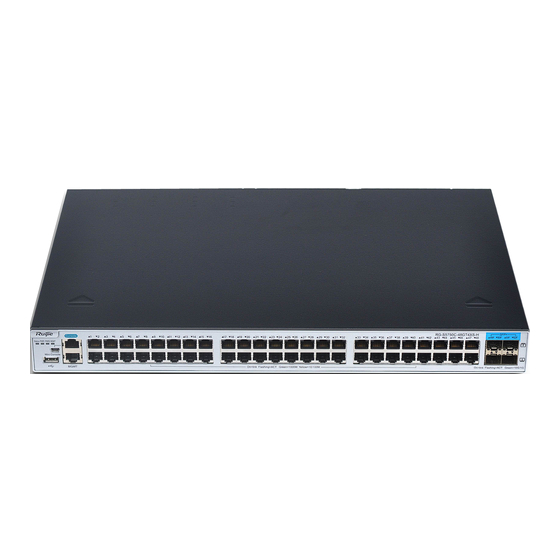
- Page 13 Hardware Installation and Reference Guide Product Overview Front Panel Figure 1-6 Front Panel of RG-S5750C-48GT4XS-H Note: 1. System status LED 7. Switch port status LED 2. Power status LED (PWR1) 8. USB port 3. Power status LED (PWR2) 9. Mini USB port 4.
- Page 14 Hardware Installation and Reference Guide Product Overview The RG-S5750C-48GT4XS-H supports two power modules. For details, see the section “Power Modules”. Dual-power input: The switch can be powered by one power module, or two power modules. When both two modules are available, the switch is powered in current sharing mode. When the switch is powered by the dual-power modules, if the system working power is greater than the capacity of single power module, power redundancy cannot work;...
- Page 15 Hardware Installation and Reference Guide Product Overview Panel State Meaning Identification 1. Temperature of inlet/outlet air exceeds the normal operating temperature range. 2. The power supplies cannot support the whole system. Check the working environment of the switch and power supplies immediately. The switch is faulty.
- Page 16 512 MB Flash Memory SDRAM 1 GB See Appendix B. Optical Module The supported module type may update without prior notification. Consult the Ruijie Networks for the latest information. Expansion 2 slots Module Slot 2 slots Supported power module: RG-PA70I ...
- Page 17 Hardware Installation and Reference Guide Product Overview Storage temperature: -40º C to 70º C Operating humidity: 10% to 90% RH Humidity Storage humidity: 5% to 95% RH Altitude 0 to 5000m Speed adjustment and fault alarm Temperature Supported Alarm GB/T 9254.1 EMI Standard Safety GB 4943.1...
- Page 18 Hardware Installation and Reference Guide Product Overview Note: 1. System status LED 7. GE SFP port 2. Power status LED (PWR1) 8. Switch port status LED 3. Power status LED (PWR2) 9. USB port 4. MGMT port status LED 10.Mini USB port 5.
- Page 19 Hardware Installation and Reference Guide Product Overview Panel State Meaning Identification The switch is not receiving power. The switch is being initialized with 3Hz Blinking green blinking. (3 Hz) Continuous blinking indicates errors. Blinking green Supports remote on/off to locate the (10Hz) switch.
- Page 20 Technical Specifications Model RG-S5750C-48SFP4XS-H Dual-core with each 1.0 GHz 8 MB BOOTROM Flash Memory 512 MB 1 GB SDRAM See Appendix B. Optical Module The supported module type may update without prior notification. Consult the Ruijie Networks for the latest information.
- Page 21 Hardware Installation and Reference Guide Product Overview 2 slots Supported expansion module : M5000H-04XS (for expansion slot 1) Expansion Module Slot If expansion module slot 1 is installed with the M5000H-04XS module, expansion module sot 2 does not support any expansion modules. ...
- Page 22 Hardware Installation and Reference Guide Product Overview Dimensions 440 mm x 340 mm x 44 mm (W x D x H) Weight 4.7kg (without packing material) Product Appearance The RG-S5750C-48SFP4XS-H Ethernet switch provides 48 GE SFP ports, 4 10GE SFP+ ports, 1 MGMT port, 1 USB port, 1 Mini USB port, and 1 Console port on the front panel, as well as 2 power module slots and 2 expansion module slots on the back panel.
- Page 23 Hardware Installation and Reference Guide Product Overview Note: 1. Expansion module slot 1 4. Power module slot 2 2. Expansion module slot 2 5. Grounding stud 3. Power module slot 1 Power Supply The RG-S5750C-48SFP4XS-H supports RG-PA150I-F. For details, see the section “Power Modules”. Dual-power input: The switch can be powered by one power module, or two power modules.
- Page 24 Hardware Installation and Reference Guide Product Overview Panel State Meaning Identification The switch is being initialized with 3Hz Blinking green blinking. (3 Hz) Continuous blinking indicates errors. Blinking green Supports remote on/off to locate the (10Hz) switch. Solid green The switch is operational. Temperature alarm: System status 1.
- Page 25 512 MB SDRAM 1 GB See Appendix B. Optical Module The supported module type may update without prior notification. Consult the Ruijie Networks for the latest information. RG-M5000E-AC500P Rated voltage: 100V to 240V Frequency: 50/60Hz Rated current: 7A to 3.5A...
- Page 26 Hardware Installation and Reference Guide Product Overview The RG-M5000E-DC500P power module is only suitable for use in the Chinese region. SFP Port Not supported 10GBbase-R SFP+ Port 1000Base-X All RJ45 ports support PoE. Each port supports up to 30W PoE. The max power is subject to the configured power supply.
- Page 27 Hardware Installation and Reference Guide Product Overview Front Panel Figure 1-18 Front Panel of RG-S5750-48GT4XS-HP-H Note: 1. System status LED 8. Switch port status LED 2. Power status LED (PWR1) 9. PoE button 3. Power status LED (PWR2) 10. USB port 4.
- Page 28 Hardware Installation and Reference Guide Product Overview When the switch is powered by the dual-power modules, if the system working power is greater than the capacity of single power module, power redundancy cannot work; if one power module fails, the switch system will be affected. Heat Dissipation The RG-S5750-48GT4XS-HP-H is designed with left and right fans for heat dissipation, thereby ensuring the normal function of the device in the specified environment.
- Page 29 Hardware Installation and Reference Guide Product Overview Panel State Meaning Identification 3. RG-PA1150P-F is used with RG- M5000E-AC500P/RG-M5000E- DC500P Check the working environment of the switch and power supplies immediately. The switch is faulty. For details, see the Solid red chapter “Troubleshooting”.
- Page 30 Flash Memory SDRAM 1 GB See Appendix B. Optical Module The supported module type may update without prior notification. Consult the Ruijie Networks for the latest information. RG-M5000E-AC500P Rated voltage: 100V to 240V Frequency: 50/60Hz Rated current: 7A to 3.5A...
- Page 31 Hardware Installation and Reference Guide Product Overview SFP Port Not supported 10GBbase-R SFP+ Port 1000Base-X All RJ45 ports support PoE. Each port supports up to 30W PoE. The max power is subject to the configured power supply. The maximum number of PoE devices supported by the switch is determined by the available PoE consumption of the switch and the actual PoE consumption of each device.
- Page 32 Hardware Installation and Reference Guide Product Overview Front Panel Figure 1-22 Front Panel of RG-S5750-24GT4XS-HP-H Note: 1. System status LED 8. Switch port status LED 2. Power status LED (PWR1) 9. PoE button 3. Power status LED (PWR2) 10. USB port 4.
- Page 33 Hardware Installation and Reference Guide Product Overview When the switch is powered by the dual-power modules, if the system working power is greater than the capacity of single power module, power redundancy cannot work; if one power module fails, the switch system will be affected. Heat Dissipation The RG-S5750-24GT4XS-HP-H is designed with left and right fans for heat dissipation, thereby ensuring the normal function of the device in the specified environment.
-
Page 34: Expansion Modules
Hardware Installation and Reference Guide Product Overview Panel State Meaning Identification 3. RG-PA1150P-F is used with RG- M5000E-AC500P/RG-M5000E- DC500P Check the working environment of the switch and power supplies immediately. The switch is faulty. For details, see the Solid red chapter “Troubleshooting”. -
Page 35: Power Modules
Hardware Installation and Reference Guide Product Overview M5000H-04XS is only supported on the expansion module slot 1 of RG-S5750C-48GT4XS-H and RG-S5750C-48SFP4XS-H. If expansion module slot 1 is installed with the M5000H-04XS module, expansion module sot 2 does not support any expansion modules. Module Description External port... - Page 36 Hardware Installation and Reference Guide Product Overview Maximum 90 V to 264 V 192 V to 288 V 47/63 Hz Voltage Input Current 12 V Output Voltage Max Current 5.83 A Output Max Power 70 W Output Input Leakage ≤1.75 mA Current Dimensions 156 mm x 50.5 mm x 38 mm...
- Page 37 Hardware Installation and Reference Guide Product Overview 1.1.2 RG-PD70I The RG-PD70I power module is only suitable for use in the Chinese region. Specification Power Model RG-PD70I (DC input) Device Model RG-S5750C-28GT4XS-H, RG-S5750C-28SFP4XS-H, RG-S5750C-48GT4XS-H Rated Voltage -36 V to -72 V Input Current 3.15 A 12 V...
- Page 38 Hardware Installation and Reference Guide Product Overview Status Solid The module is operational. green 1.1.3 RG-PA150I-F Specification Power Model RG-PA150I-F (AC input) RG-PA150I-F (HVDC input) RG-S5750C-48GT4XS-H RG-S5750C-48GT4XS-H Device Model 100 V to 240 V Rated Voltage 240 V 50/60 Hz Maximum 90 V to 264 V 192 V to 288 V...
- Page 39 Hardware Installation and Reference Guide Product Overview Supports to disconnect one redundant power module from the outside Hot Swapping power supply system, plug and unplug power modules while the device is powered on. Power Supply Alarm Alarms power supply faults through the power status LED. Panel Identification State Meaning Status...
- Page 40 Hardware Installation and Reference Guide Product Overview Panel Identification State Meaning Solid red There is no power output or output error occurs. Status Solid Output is OK. green Solid red Input error. Status Solid Input is OK. green 1.1.5 RG-M5000E-DC500P The RG-M5000E-DC500P power module is only suitable for use in the Chinese region.
- Page 41 Hardware Installation and Reference Guide Product Overview Status Solid Output is OK. green Solid red Input error. Status Solid Input is OK. green 1.1.6 RG-PA1150P-F Specification Power Model RG-PA1150P-F (AC input) RG-PA1150P-F (HVDC input) RG-S5750-48GT4XS-HP-H RG-S5750-48GT4XS-HP-H Device Model RG-S5750-24GT4XS-HP-H RG-S5750-24GT4XS-HP-H 100 V to 240 V 240 V Rated Voltage...
- Page 42 Hardware Installation and Reference Guide Product Overview The RG-PA1150P-F power module is only suitable for use in the Chinese region. Panel Identification State Meaning There is no power output or output error occurs. Status Solid Output is OK. green...
-
Page 43: Preparation Before Installation
Hardware Installation and Reference Guide Preparation before Installation 2 Preparation before Installation 2.1 Safety Suggestions To avoid personal injury and equipment damage, please carefully read the safety suggestions before you install the RG-S5750H series. The following safety suggestions may not cover all possible dangers. This equipment is not suitable for use in locations where children are likely to be present. - Page 44 Hardware Installation and Reference Guide Preparation before Installation Direct or indirect touch through a wet object on high-voltage and commercial electricity may bring a fatal danger. If a power supply system is equipped with a leakage protector (also referred to as "leakage current switch"...
-
Page 45: Installation Site Requirements
Hardware Installation and Reference Guide Preparation before Installation 2.2 Installation Site Requirements The RG-S5750H series must be used indoors. To ensure its functioning and prolong its service life, the installation site must meet the following requirements. 2.2.1 Ventilation RG-S5750H should be placed at least 10 cm away from surrounding walls to effective ventilation and heat dissipation. - Page 46 Hardware Installation and Reference Guide Preparation before Installation of some parts. The equipment room should be protected from the intrusion of harmful gases (for example, SO S, NO and Cl ), whose requirements are listed in the following table. Average (mg/m Maximum (mg/m 2.2.4 Grounding A good grounding system is the basis for the stable and reliable operation of the RG-S5750H series,...
-
Page 47: Lightning Resistance
Hardware Installation and Reference Guide Preparation before Installation 2.2.5 Lightning Resistance When the AC power cable is imported outdoors and directly connected to the power port of the switch, lightning preventing wires should be adopted to prevent the switch from being hit by lightning shocks. The lightning preventing wires can be fixed on the cabinet, work station, or the equipment room’s wall through line buckles and screws. -
Page 48: Precautions For Fiber Connections
Hardware Installation and Reference Guide Preparation before Installation Cables must be connected to interfaces inside the room to prevent damage to the device’s signal ports caused by over-voltage and over-current generated by thunder and lightning. 2.3 Precautions for Fiber Connections Before you connect the fibers, check that the optical connector type and fiber type match the optical interface type used. -
Page 49: Product Installation
Hardware Installation and Reference Guide Product Installation 3 Product Installation Please ensure that you have carefully read Chapter 2 and make sure that the requirements set forth in Chapter 2 have been met. 3.1 Installation Flowchart 3.2 Pre-installation Confirmation Before installation, please confirm the following points: ... -
Page 50: Installing The Switch
Hardware Installation and Reference Guide Product Installation 3.3 Installing the Switch Precautions During installation, note the following points: Connect the power cables of different colors to the corresponding grounding posts. Ensure that the connected power cables have sound contact. ... -
Page 51: Mounting The Switch On A Table
Hardware Installation and Reference Guide Product Installation 3.3.3 Mounting the Switch on a Table Users may not have a 19-inch rack. Thus, it is common to mount the switch on the workbench with 2 simple steps: Attach the four rubber feet to the recessed areas on the bottom of the switch. ... - Page 52 Hardware Installation and Reference Guide Product Installation Insert the expansion module smoothly. Pay attention to the direction of the expansion panel to avoid wrong insertion. Do not hold the edge of the PCB or collide the components on the PCB. If it is difficult or even impossible to insert the module, pull out the module, make sure the expansion module and guide rail are well aligned, and then insert the module again.
- Page 53 Hardware Installation and Reference Guide Product Installation Install a baffle on the location where an expansion module is removed to ensure normal ventilation and dissipation and avoid dust in the chassis. 3.5 Installing and Removing the Power Modules Wear anti-static gloves before the following operations. Installing an RG-PA70I or RG-PA150I-F Power Module Step 1: Take a new power module out of the package and confirm the input mode and the input parameters of the power module match the requirements.
- Page 54 Hardware Installation and Reference Guide Product Installation Remove the power module uprightly and slowly. Install a baffle in the location where the power module is removed to ensure the normal ventilation and dissipation and avoid the dust in the chassis. Installing an RG-PD70I Power Module Step 1: Take a new power module out of the package and confirm the input mode and the input parameters of the power module match the requirements.
- Page 55 Hardware Installation and Reference Guide Product Installation Insert the power module smoothly. Please pay attention to the direction of the power panel to avoid wrong insertion. If it is difficult or even impossible to insert the module, pull out the module, make sure the expansion module and guide rail are well aligned, and then insert the module again.
-
Page 56: Grounding The Switch
Hardware Installation and Reference Guide Product Installation If you want to use RG-M5000E-DC500P to provide power for RG-S5750-24GT/8SFP-P or RG- S5750-48GT/4SFP-P, please refer to the following figure and installation steps. Figure 3-10 Power Supply Connection Installation Steps Take out power supply RG-M5000E-DC500P and DC power cord, and insert the power supply into the power slot. -
Page 57: Connecting The External Port Cables
Hardware Installation and Reference Guide Product Installation The maintenance personnel shall check whether or not the AC socket powering the switch is well connected to the building protective earth (PE). If not, the personnel shall connect the grounding lug of the AC socket with the PE by using a grounding connector. The AC socket shall be installed near the equipment and shall be easily used. -
Page 58: Checking After Installation
Hardware Installation and Reference Guide Product Installation 3.9 Checking after Installation Before checking the installation, switch off the power supply to avoid any personal injury or damage to the component due to connection errors. Check that the ground line is connected. ... -
Page 59: System Debugging
Hardware Installation and Reference Guide System Debugging 4 System Debugging 4.1 Establishing the Configuration Environment Establishing the Configuration Environment Use the Console cable to connect the PC to the switch. Figure 4-1 Configuration Environment Connecting the Console Cable The RG-S5750H series switches support the following connecting ways: Step 1: Connect the serial &... - Page 60 Hardware Installation and Reference Guide System Debugging Step 1: Start the PC and run the terminal simulation program on the PC, such as Terminal on Windows 3.1 or HyperTerminal on Windows 95/98/NT/2000/XP. Step 2: Set terminal parameters. The parameters are as follows: baud rate 9600, data bit 8, parity check none, stop bit 1, and flow control as none.
-
Page 61: Power-On Startup
Hardware Installation and Reference Guide System Debugging After setting the parameters, click OK to enter the super terminal page. 4.2 Power-on Startup Checking before Power-on The switch is fully grounded. The power cable is correctly connected. The power cable is buckled after connected. ... -
Page 62: Monitoring And Maintenance
Hardware Installation and Reference Guide Monitoring and Maintenance 5 Monitoring and Maintenance Monitoring LED When the RG-S5750H is running, users can monitor the status of host and each module by inspecting corresponding LEDs. When the system status LED is red, it means the system has a fault, in which case you can determine and eliminate the fault by viewing with the management software. - Page 63 Throwing the battery into a fire or oven, or mechanically crushing or cutting it may cause the battery to explode. Replacing Fuses Please contact the TAC of Ruijie Networks for replacing fuses. Technical staff of Ruijie Networks will replace the fuse of the same model.
-
Page 64: General Troubleshooting Flowchart
Fault 1: The password to login the management interface is lost. Fault Description: A password is manually configured but it is forgotten or lost, causing failure in login and configuration. Troubleshooting: Contact TAC of Ruijie Networks for technical support. Fault 2: The AC power module does not work. Fault Description:... - Page 65 Check whether the configuration of the serial port on the super terminal is the same as that described in Configuration Guide. If not, modify the serial port configuration parameters. If there is still no serial port printed information, please contact TAC of Ruijie Networks for technical support.
- Page 66 Hardware Installation and Reference Guide Troubleshooting Check whether the receiving and sending ends are wrongly connected. The sending end of the fiber interface needs to be connected to the receiving end of the other fiber interface. You can check by changing the sequence in which the two optical fibers are connected on the optical module.
-
Page 67: Appendix A Connectors And Connection Media
Hardware Installation and Reference Guide Appendix A Connectors and Connection Media Appendix A Connectors and Connection Media 1000BASE-T/100BASE-TX/10BASE-T Ports The 1000BASE-T/100BASE-TX/10BASE-T is a port that supports adaptation of three rates, and automatic MDI/MDIX Crossover at these three rates. The 1000BASE-T complies with IEEE 802.3ab, and uses the cable of 100-ohm Category-5 or Supper Category-5 UTP or STP, which can be up to 100 m. - Page 68 Hardware Installation and Reference Guide Appendix A Connectors and Connection Media Optical Fiber Connection For the optical fiber ports, select single-mode or multiple-mode optical fibers for connection according to the fiber module connected. The connection schematic diagram is shown in Figure A-4: Figure A-4 Schematic Diagram for optical fiber connection...
-
Page 69: Appendix B Mini-Gbic, 10G Sfp+ And 40G Qsfp
Appendix B Mini-GBIC, 10G SFP+ and 40G QSFP+ Modules Specifications Ruijie Networks provides various Gigabit SFP (Mini-GBIC modules), and 10G SFP transceivers for interfaces of modules on the switch. You can select the most suitable SFP transceivers as needed. This appendix describes the models and specifications of some of the Gigabit and 10G SFP transceivers for your reference. - Page 70 Hardware Installation and Reference Guide Appendix B Mini-GBIC, 10G SFP+ and 40G QSFP+ Modules Specifications SMF=Single-mode fiber GE Mini-GBIC (SFP) Models and Specifications Table B-2 Existing GE Mini-GBIC (SFP) Models Supported Transmit Receive Wavelength Fiber (dBm) (dBm) Model (nm) type (Yes/No) MINI-GBIC-SX-MM850 -9.5...
- Page 71 Hardware Installation and Reference Guide Appendix B Mini-GBIC, 10G SFP+ and 40G QSFP+ Modules Specifications 62.5/125 275 m MINI-GBIC-SX-MM850 50/125 550 m MINI-GBIC-LX-SM1310 9/125 10 km 62.5/125 275 m GE-eSFP-SX-MM850 50/125 550 m GE-eSFP-LX-SM1310 9/125 10 km GE-SFP-LX-SM1310 9/125 10 km MINI-GBIC-LH40- 9/125 40 km...
- Page 72 Hardware Installation and Reference Guide Appendix B Mini-GBIC, 10G SFP+ and 40G QSFP+ Modules Specifications Table B-4 Existing Mini-GBIC-GT models supported: Standard Model 1000Base-T Mini-GBIC-GT Table B-4 (continued) Cabling 1000baseT Cable Type DDM (Yes/No) Distance Mini-GBIC-GT Catogary-5 or above UTP/STP 100 m 10G SFP+ Models and Specifications Table B-5 Existing 10G SFP+ models supported:...
- Page 73 Passive SFP+ 10.3125 supported + models may update without prior notification, contact Ruijie Networks after-sales personnel for the latest information. SPF+ copper cables can be inserted to ports directly without the help of other cables. 40G QSFP+ Models and Specifications...
- Page 74 Hardware Installation and Reference Guide Appendix B Mini-GBIC, 10G SFP+ and 40G QSFP+ Modules Specifications 150 m 4700 (OM4) 300 m 2000 40G-QSFP- (OM3) (840 ,860) LSR-MM850 400 m 4700 (OM4) (1264.5,1277.5) 40G-QSFP- (1284.5,1297.5) 10 km LR4-SM1310 (1304.5,1317.5) (1324.5,1337.5) 40G-QSFP- LR4-PSM- (1260,1355) MPO/APC...
-
Page 75: Appendix C Lightning Protection
Hardware Installation and Reference Guide Appendix C Lightning Protection Appendix C Lightning Protection Installing AC Power Arrester (lightning protection cable row) The external lightning protection cable row shall be used on the AC power port to prevent the switch from being struck by lightning when the AC power cable is introduced from the outdoor and directly connected to the power port of the switch. - Page 76 Hardware Installation and Reference Guide Appendix C Lightning Protection During the switch usage, the Ethernet port arrester shall be connected to the switch to prevent the switch damage by lightning before the outdoor network cable connects to the switch. Tools: Cross or straight screwdriver, Multimeter, Diagonal pliers Installation Steps: ...
- Page 77 Hardware Installation and Reference Guide Appendix C Lightning Protection Ethenet Port Arrester Hardware Installation Guide, which contains the technical specification and the maintenance and installation of the arrester. You may pay attention to the following conditions during the actual installation to avoid influencing the performance of the Ethernet port arrester: ...
-
Page 78: Appendix D Cabling Recommendations
Hardware Installation and Reference Guide Appendix D Cabling Recommendations Appendix D Cabling Recommendations When RG-S5750H series switches are installed in standard 19-inch racks, route cable bundles upward or downward along the sides of the rack depends on the actual situation in the equipment room. All cable connectors should be placed at the bottom of the rack rather than be exposed outside of the cabinet. - Page 79 Hardware Installation and Reference Guide Appendix D Cabling Recommendations Route and bundle power, signal, ground cables separately. When the cables are close to each other, cross them. When power cables run parallel to signal cables, the distance between them must b ...
- Page 80 Hardware Installation and Reference Guide Appendix D Cabling Recommendations Wrap up unnecessary or excess cables and bind them to the appropriate rack position, where device operation is not affected and no damages occur to the device and cables during debugging. ...
- Page 81 Hardware Installation and Reference Guide Appendix D Cabling Recommendations Bundle cables of the same type and running in the same direction into groups. Keep cables clean and straight. Cables shall be tied according to the following table. Diameter of Cable Bundle (mm) Space between Bundles (mm) 80 to 150 10 to 30...
-
Page 82: Appendix E Site Selection
Hardware Installation and Reference Guide Appendix E Site Selection Appendix E Site Selection The machine room should be at least 5km away from the heavy pollution source such as the smelter, coal mine and thermal power plant, 3.7km away from the medium pollution source such as the chemical industry, rubber industry and electroplating industry, and 2km away from the light pollution source such as the food manufacturer and leather plant. -
Page 83: Appendix F Mini Usb Console Driver Installation
Hardware Installation and Reference Guide Appendix F Mini USB Console Driver Installation Appendix F Mini USB Console Driver Installation The Mini USB Console driver can be downloaded on the official TI website (http://www.ti.com/). The driver is now supported only on 32-bit Windows XP, 64-bit Windows XP, 32-bit Window Vista, 64-bit Window Vista, 32-bit Windows 7, and 64-bit Windows 7. - Page 84 Hardware Installation and Reference Guide Appendix F Mini USB Console Driver Installation Step 3: Select the unpackage directory and click Install. Step 4: After the driver is installed, click Finish.
- Page 85 Hardware Installation and Reference Guide Appendix F Mini USB Console Driver Installation After the Mini USB Console driver is installed, you are able to perform commissioning on devices with Mini USB ports using Type-A male USB to male Mini USB cables. Right click Computer, choose Manage-Device Manager-Ports (COM &...
Need help?
Do you have a question about the RG-S5750-H Series and is the answer not in the manual?
Questions and answers