Table of Contents
Advertisement
Quick Links
Advertisement
Table of Contents
Troubleshooting

Related Manuals for Ruijie RG-S6920-4C Series


Summary of Contents for Ruijie RG-S6920-4C Series
- Page 1 Ruijie RG-S6920-4C Series Switches Hardware Installation and Reference Guide...
- Page 2 This document is provided “as is”. The contents of this document are subject to change without any notice. Please obtain the latest information through the Ruijie Networks website. Ruijie Networks endeavors to ensure content accuracy and will not shoulder any responsibility for losses and damages caused due to content omissions, inaccuracies or errors.
- Page 3 Appendix B "10G, 25G, 40G and 100G Modules" Appendix C “Lightening Protection” Appendix D “Cabling Recommendations in Installation” Appendix E “Site Selection” Obtaining Technical Assistance Ruijie Networks Website: https://www.ruijienetworks.com/ Technical Support Website: https://ruijienetworks.com/support Case Portal: https://caseportal.ruijienetworks.com ...
- Page 4 Describes network protocols and related mechanisms that supported by the Configuration Guide product, with configuration examples. Describes the related configuration commands, including command modes, Command Reference parameter descriptions, usage guides, and related examples. Symbol Conventions Means reader take note. Notes contain helpful suggestions or references. Means reader be careful.
-
Page 5: Product Overview
Rated current: 5.2 A to 14 A Power Less than 2400 W Consumption Refer to Appendix B Optical Module The supported modules update at any time, contact Ruijie Networks for details. SFP+ Port Supported QSFP28 Port Supported FC Port Unsupported... - Page 6 Hardware Installation and Reference Guide Product Overview Temperature Support temperature warning and over-heating protection. Warning EMC Standards GB9254-2008 CLASS A Safety Standards GB4943-2011 Working 0 ° C to 40 ° C (32 ° F to 104 ° F) Temperature Storage -40 °...
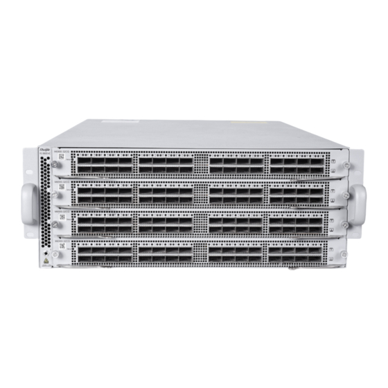
- Page 7 Hardware Installation and Reference Guide Product Overview Notes: Line Card Indicator Screws QSFP28 Port Line Card Handle QSFP28 Port Indicator Ground for ESD Wrist Strap Banana Jack The S6920-4C supports 100G QSFP28 module and 10G SFP+ module. Rear Panel Figure 1-3 Rear Panel of the S6920-4C Notes: Power Module Slot USB2.0 Port...
- Page 8 To protect the data and avoid device damage, use qualified USB flash disks of good brands. At the same time, the local USB port is compatible with most of the USB controllers except some USB flash disks. RG-S6920-4C series switches support debugging, configuration, maintenance, management and host software uploading of Console ports.
- Page 9 40G/100Gbps. Power Supply The RG-S6920-4C series switches support power supply the RG-PA1200I-F. The smart power supply module supports power management, and the host can read input power, input current, and temperature in real time. The power supply module supports hot swapping.
- Page 10 The working temperature of the RG-S6920-4C switches is 0° C to 45° C (32° F to 113° F), and the heat dissipation design needs to ensure the stability, safety and maintainability in such environment. The RG-S6920-4C series switches adopt fan ventilation and forced convection to ensure the device can work normally in specified environment. Dust the device every three months to avoid blocking the ventilation openings.
-
Page 11: Preparation Before Installation
Hardware Installation and Reference Guide Preparation before Installation 2 Preparation before Installation 2.1 Safety Precautions To avoid body injury and device damage, please carefully read the safety precautions before you install the RG- S6920-4C. The following safety precautions do not cover all possible dangers. 2.1.1 Installation Safety ... -
Page 12: Laser Safety
Hardware Installation and Reference Guide Preparation before Installation Any nonstandard and inaccurate electrical operation can cause accidents such as fires or electrical attacks, thus causing severe, or even fatal damages to human bodies and the devices. Direct or indirect touch through a wet object on high-voltage and mains supply can bring a fatal danger. 2.1.4 Electrostatic Discharge Damage Precautions The RG-S6920-4C designing gives a great consideration to prevent electrostatic discharge damage and adopts multiple measures. -
Page 13: Ventilation Requirements
Hardware Installation and Reference Guide Preparation before Installation Install the switch in an open cabinet as much as possible. If you install the switch inside a closed cabinet, be sure that the cabinet has a good ventilation and heat dissipation system. ... -
Page 14: System Grounding Requirements
All the above constitute the comprehensive grounding requirements. The grounding resistance should be less than 1Ω. There is one grounding connector at the left bottom of the chassis of RG-S6920-4C series switches. The grounding connector is pasted with conspicuous warning labels. -
Page 15: Emi Consideration
Hardware Installation and Reference Guide Preparation before Installation 2.2.6 EMI Consideration Various interference sources, from either outside or inside the device or application system, affect the system in the conductive ways such as capacitive coupling, inductive coupling, and electromagnetic radiation. There are two types of electromagnetic interferences: radiated interference and conducted interference, depending on the type of the propagation path. -
Page 16: Unpacking And Checking
Air-laid paper, fiber end microscope Meter Multimeter, errormeter, optic-power meter RG-S6920-4C series is not shipped with a tool kit. You need to prepare a tool kit by yourself. 2.5 Unpacking and Checking Goods Checklist Chassis, Yellow/green grounding cables; Quick installation guide; Packing list, Pouched... -
Page 17: Product Installation
Product Installation 3 Product Installation RG-S6920-4C series Ethernet switch must be used and fixed in the room. Make sure you have carefully read part 2, and be sure that the requirements set forth in part 2 have been met. 3.1 Installation Procedure... -
Page 18: Cabinet Installation
Hardware Installation and Reference Guide Product Installation The related network cables have already been deployed at the installation location. 3.3 Cabinet Installation Precautions When you install the cabinet, pay attention to the following requirements: All expansion bolts for fastening the cabinet base to the ground should be installed and tightened in sequence from bottom up (large plain washer, spring washer, and nut), and the installation holes on the base and the expansion bolts should be well aligned. - Page 19 During the process of installation, keep the front panel of the switch forward. It is recommended use tray to install the RG-S6920-4C series switches and fix the tray on the bracket, or use the rear bracket provided with the switches.
-
Page 20: Installing And Removing A Fan Module
Hardware Installation and Reference Guide Product Installation Distinguish the left and the right rear brackets according to the marked directions. The rear brackets provided are only applicable for cabinets with depth of 800mm to 1200mm. 3.5 Installing and Removing a Fan Module Wear anti-static gloves before the following operations. - Page 21 Hardware Installation and Reference Guide Product Installation If the screws cannot be tightened, it is probably because the fan module is not fully inserted. Please check it carefully. Power modules and fan modules with different air direction cannot be used together. Removing a Fan Module Loosen the captive screws of the fan module with a screwdriver.
- Page 22 Hardware Installation and Reference Guide Product Installation Insert the power module smoothly. Please pay attention to the direction of the power panel to avoid wrong insertion. If it is difficult or even impossible to insert the module, pull out the module, make sure the expansion module and guide rail are well aligned, and then insert the module again.
- Page 23 Hardware Installation and Reference Guide Product Installation Check whether the power cord container is correctly installed. If you can remove the strap without pressing buckle A, the strap may be installed incorrectly. Try the other side of the strap. Attach the power cord container to the installation hole of the power module. Plug the power cord into the connector.
- Page 24 Hardware Installation and Reference Guide Product Installation Remove the power module slowly. Install a filler panel in the location where the power module is removed to ensure the normal ventilation and dissipation and avoid the dust in the chassis. 3.7 Grounding A PGND is installed on the back of RG-S6920-4C.
-
Page 25: Connecting The External Interface Cables
Hardware Installation and Reference Guide Product Installation Connect the RJ45 connector to the Console interface of the management engine module with shipped console cable, and connect the DB9 connector to the NM or control terminal. By default, the baud rate is 115200, data bit 8, parity check none, stop bit 1, and flow control none. 3.9 Connecting the External Interface Cables Precautions ... - Page 26 Hardware Installation and Reference Guide Product Installation Verify that the cabinet has been fastened completely, and does not move or tilt. Verify that the equipment has been installed in the cabinet, and all the cables have been fastened to the cabinet. ...
-
Page 27: System Debugging
Hardware Installation and Reference Guide System Debugging 4 System Debugging 4.1 Establishing the Configuration Environment Establishing the Configuration Environment Connect the PC to the console port of the switch through the console cable, as shown in Figure 4-1. Figure 4-1 Schematic diagram of the configuration environment Connecting the Console Cable Connect one end of the DB-9 jack of the console cable to the serial port of the PC. - Page 28 Hardware Installation and Reference Guide System Debugging Figure 4-2 Enter the name of the new connection and click OK. A window appears as shown in Figure 4-3. In the column of Connect Using field, select the serial port you want to use. Figure 4-3 After the serial port is selected, please click OK.
-
Page 29: Power-On Startup
Hardware Installation and Reference Guide System Debugging After the serial port parameters are set, click OK to enter hyper terminal window. 4.2 Power-on Startup Checking before Power-on Check if the switch is fully grounded. Check if the fan module and the power module are correctly installed. ... -
Page 30: Monitoring And Maintenance
Working status of fan and power supply Temperature status For the monitoring commands, refer to RG-S6920-4C Series Switch RGOS Configuration Guide. 5.2 Hardware Maintenance Expansion Module Maintenance To replace a board, do replacement according to the instructions provided in Sections of Installing Modules and Removing Modules. - Page 31 Replacing Lithium Battery The built-in lithium batteries can support the real time clock of the RG-S6920-4C series switches without external power supply. Please contact the technical support representatives of Ruijie Networks for replacing lithium batteries. Technical staff of Ruijie Networks will replace the battery of the same model.
-
Page 32: Troubleshooting
Check the indicators on the device and the modules Check the connection of the serial ports and its parameters Check the connection of the fibers or cables of various ports Contact Technical Support of Ruijie Networks for hardware problems - 30 -... -
Page 33: Common Troubleshooting Procedures
RG-S6920-4C Software Configuration Guide. If not, modify the serial port configuration parameters. If there is still no serial port printed information, please contact Ruijie Customer Service Department for technical support. - Page 34 Check whether the module is inserted correctly. If the newly-inserted module still cannot be powered on even though the checking is ok, please contact Ruijie Customer Service Department for technical support. Fault 7: The link cannot be set up between fiber interfaces [Fault Description] The system runs normally.
-
Page 35: Appendix A Connectors And Connection Media
Hardware Installation and Reference Guide Appendix A Connectors and Connection Media Appendix A Connectors and Connection Media 10GBASE-T/1000BASE-T/100BASE-TX Port 10GBASE-T/1000BASE-T/100BASE-TX is a port that supports self-adaptation of three rates, and automatic MDI/MDIX Crossover at these three rates. 10GBASE-T complies with IEEE 802.3an standard, and the supported cables and cabling distances are listed in the following table. - Page 36 Hardware Installation and Reference Guide Appendix A Connectors and Connection Media Figure A-1 Four twisted pairs of the 1000BASE-T In addition to the above cables, the 100BASE-TX can use up to 100m of 100-ohm CAT5. Figure A-2 shows the definition of pin signal concerning the 100BASE-TX: Figure A-2 Definition of pin signal concerning the 100BASE-TX Socket Plug...
-
Page 37: Appendix B Mini-Gbic, 10G, 40G And 100G Module
Hardware Installation and Reference Guide Appendix B Mini-GBIC, 10G, 40G and 100G Module Appendix B Mini-GBIC, 10G, 40G and 100G Module We provide mini-GBIC module, 10G SFP+ modules, 40G QSFP+ modules, 100G QSFP28 modules. According to the interface type of the switch module. You can select modules to suit your specific needs. The following models and technical specifications of mini-GBIC modules, 10G SFP+ modules, 40G QSFP+ modules, 100G QSFP28 modules are listed for your reference. - Page 38 Hardware Installation and Reference Guide Appendix B Mini-GBIC, 10G, 40G and 100G Module (μm) Type distance Light (dbm) Light (dbm) (MHz·km) 62.5 XG-SFP-SR- 2000 300m -7.5 MM850 connecto XG-SFP-LR-S 1310 10km -8.2 -10.3 M1310 connecto XG-SFP-ER-S 1550 40km -4.7 -11.3 M1550 connecto XG-SFP-ZR-S...
- Page 39 Hardware Installation and Reference Guide Appendix B Mini-GBIC, 10G, 40G and 100G Module 25GE, 5m, SFP28 Passive SFP28 25.78125 Models and Technical Specifications of the 40G QSFP+ Module 40G QSFP+ optical modules Intensity Wavel Core Modular Intensity of Optical Model ength Size Bandwidth...
- Page 40 Hardware Installation and Reference Guide Appendix B Mini-GBIC, 10G, 40G and 100G Module 100G QSFP28 copper modules Copper Conductor Support Module Connector Model Cable Wire Diameter Data Rate(Gb/s) Type Type Length (m) (AWG) (Yes/No) 4lanes*25.7812 100GE, 1m, QSFP28 Passive QSFP28 5 (Perlane) 4lanes*25.7812 100GE, 3m, QSFP28...
-
Page 41: Appendix C Lightning Protection
Hardware Installation and Reference Guide Appendix C Lightning Protection Appendix C Lightning Protection Installing AC Power Arrester (lightning protection cable row) The external lightning protection cable row should be used on the AC power port to prevent the switch from being struck by lightning when the AC power cable is introduced from the outdoor and directly connected to the power port of the switch. - Page 42 Hardware Installation and Reference Guide Appendix C Lightning Protection Installing the Ethernet Port Arrester During the switch usage, the Ethernet port arrester should be connected to the switch to prevent the switch damage by lightning before the outdoor network cable connects to the switch . Tools: Cross or straight screwdriver, Multimeter, Diagonal pliers Installation Steps: Tear one side of the protection paper for the double-sided adhesive tape and paste the tape to the framework of the...
- Page 43 Hardware Installation and Reference Guide Appendix C Lightning Protection You should pay attention to the following conditions during the actual installation to avoid influencing the performance of the Ethernet port arrester: Reversed direction of the arrester installation. You shall connect the external network cable to the “IN” end and connect the switch Ethernet port to the “OUT”...
-
Page 44: Appendix D Cabling Recommendations In Installation
Hardware Installation and Reference Guide Appendix D Cabling Recommendations in Installation Appendix D Cabling Recommendations in Installation When the switches are installed in standard 19-inch cabinets, the cables are tied in the binding rack on the cabinet by the cable management bracket, and top cabling or bottom cabling is adopted according to the actual situation in the equipment room. - Page 45 Hardware Installation and Reference Guide Appendix D Cabling Recommendations in Installation Cables of different types (such as power cords, signal cables, and grounding cables) should be separated in cabling and bundling and no mixed bundling is allowed. When they are close, crossover cabling can be adopted. In the case of parallel cabling, power cords and signal cables should maintain a distance not less than 30 mm.
- Page 46 Hardware Installation and Reference Guide Appendix D Cabling Recommendations in Installation Cables not to be assembled or remaining parts of cables should be folded and placed in a proper position of the cabinet or cabling slot. The proper position indicates a position that will not affect device running or cause device damage or cable damage during commissioning.
- Page 47 Hardware Installation and Reference Guide Appendix D Cabling Recommendations in Installation Figure D-4 Cable fastening The hard power cable should be fastened at the terminal connection area to prevent stress on terminal connection and cable. Do not use self-tapping screws to fasten terminals. ...
-
Page 48: Appendix E Site Selection
Hardware Installation and Reference Guide Appendix E Site Selection Appendix E Site Selection The machine room should be at least 5km away from the heavy pollution source such as the smelter, coal mine and thermal power plant, 3.7km away from the medium pollution source such as the chemical industry, rubber industry and electroplating industry, and 2km away from the light pollution source such as the food manufacturer and leather plant.
Need help?
Do you have a question about the RG-S6920-4C Series and is the answer not in the manual?
Questions and answers