
Related Manuals for Generac Power Systems Power Zone 410


Summary of Contents for Generac Power Systems Power Zone 410
- Page 1 ® Owner’s Manual ® Power Zone Gateway for use with Power Zone 410 SAVE THIS MANUAL FOR FUTURE REFERENCE...
- Page 2 WARNING CANCER AND REPRODUCTIVE HARM www.P65Warnings.ca.gov. (000393a) Owner’s Manual for Power Zone Gateway on PZ 410...
-
Page 3: Table Of Contents
Table of Contents Section 1: Introduction and Safety Calendars ............17 Set Date/Time ............17 Introduction ............1 Communications ..........17 Read This Manual Thoroughly ........1 Ethernet Port Setup ........... 18 Safety Rules ............1 External Interfaces ............18 General Hazards ............2 IP Whitelisting ............25 Electrical Hazards ............2 Email .................26 Section 2: General Information... - Page 4 This page intentionally left blank. Owner’s Manual for Power Zone Gateway on PZ 410...
-
Page 5: Section 1: Introduction And Safety
Section 1: Introduction and Safety Introduction DANGER Thank you for purchasing a Generac Power Systems, Inc. product. This unit has been designed to provide high Indicates a hazardous situation which, if not avoided, performance, efficient operation and years of use when will result in death or serious injury. -
Page 6: General Hazards
Introduction and Safety General Hazards WARNING WARNING Electrocution. More than one live high voltage circuit is present. Disconnect all power Equipment damage. Only qualified service personnel may sources before servicing. Failure to do so install, operate, and maintain this equipment. Failure to could result in death or serious injury. -
Page 7: Section 2: General Information
General Information Section 2: General Information Equipment Description Codes and Standards • The Generac Power Zone Gateway (Assembly No. UL 2200 A0002163973) is a user interface for the Power Zone • ANSI/CAN/ULC 6200: ETL approval system. The Gateway can be used in applications other •... -
Page 8: Specifications
General Information Specifications Environmental Specifications Operating Temperature -40 °F (-40 °C) to 140 °F (60 °C) Humidity 5% to 90% non-condensing Enclosure UL Type IP2X Weight 0.5 lbs Power Supply Requirements Power Supply Voltage 7 to 35 V (12 / 24 V nominal) Power Supply Usage 0.5 A (maximum during power up) -
Page 9: Connection Locations
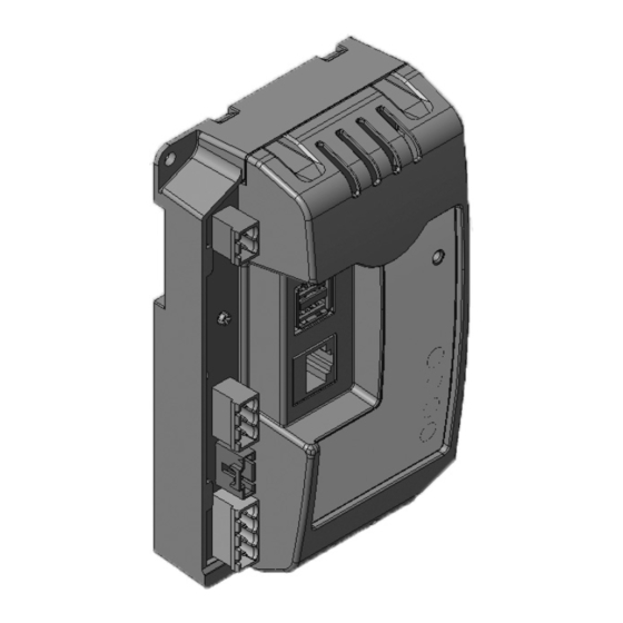
General Information Connection Locations 013864 Figure 2-1. Connection Locations (Bottom View) Power and RS-485 Connec- Communication LED (Green) USB 1 Connection tor (Gen. Controller) Power LED (Red) Aux RS-232 Port USB 2 Connection Aux Power Connection Aux RS-485 Port Ethernet Connection (Common with D) NOTE: See for more information regarding the connections and LEDs. -
Page 10: Dimensions
General Information Dimensions 013865 013866 Figure 2-2. Gateway Enclosure Dimensions 5.39 in (136.8 mm) 2.0 in (51 mm) 2.89 in (73.3 mm) 5.87 in (149 mm) 3.36 in (85.5 mm) Owner’s Manual for Power Zone Gateway on PZ 410... -
Page 11: Section 3: Installation And Operation
Green LED: Represents RS-485 (only) communi- required. This information can be accessed via the cation status. Power Zone 410’s Display. See Technical Manual – If green LED is blinking, RS-485 communication Power Zone Controller for further details. is working properly. The blinking rate will be 0.25 NOTE: The IP address and subnet mask on your PC's seconds on and 0.25 seconds off (2 Hz). -
Page 12: Home Screen
Installation and Operation Home Screen Figure 3-1. This screen displays bar graphs for the most common measurements, and an overall health check for the generator. The number of displayed mea- surements will change depending on whether or not the generator is running. 014621 Figure 3-1. -
Page 13: Top Banner
Installation and Operation Top Banner 007516 Figure 3-3. Top Banner Features (A) Keyswitch Status A red LED indicates the key is in the OFF position. A green LED indicates the key is in the AUTOMATIC posi- tion. An orange LED indicates the key is in the MANUAL position. -
Page 14: Bottom Banner
Installation and Operation Bottom Banner Figure 3-5. All of the displays and features of Power Zone are accessed via a nested menu system. Navigation is performed by selecting the relevant icon at the bottom of the screen. The icons are always visible and include a BACK icon to navigate back to the top layer. -
Page 15: Home Screen Bargraphs
Installation and Operation Home Screen Bargraphs NOTE: The “Check Engine” icon is displayed only for emissions related Diagnostic Trouble Codes (DTCs). Figure 3-6. The center of the screen contains data in Normally, these DTCs cannot be cleared manually. They the form of bargraphs. The color of the bar changes to will clear when the system has met the required condi- yellow once the measurement triggers a warning (either tions for the required length of time or number of run... -
Page 16: Language
Installation and Operation Language Changing the date/time on the Gateway means a change to the “System Time” and this will eventually change all Figure 3-9. The screen is designed to be multi-lin- other connected equipment (displays and modules) in the gual. -
Page 17: Editing
Installation and Operation 007525 Figure 3-13. Shutdown Alarm Condition (Red) 007528 Figure 3-15. Numeric Value Editing (with ranges) 007526 Figure 3-14. Warning Condition (Yellow) Editing Editing of configuration parameter values is performed by two methods: by entering a value (Figure 3-15) or selecting a value using the pull down selection box (Figure... -
Page 18: Screen Icon Details
Installation and Operation Screen Icon Details warning will display and prevent saving of data. The range will be displayed above the keyboard entry as shown in Figure 3-15. Home Screen This screen displays bar graphs for the most common measurements, and an overall health check for the gen- erator. -
Page 19: System Detail Menu
Installation and Operation 014628 Figure 3-21. Alternator Settings System Detail Menu The System Detail menu provides access to the alarm 014629 logs, run logs and maintenance logs, contact information, Figure 3-22. Reset Alarms, Warnings, and Maintenance system notes, and maintenance notes. Alarm, Warning, Run, and Maintenance Logs Alarms and Warnings 3-23. -
Page 20: Setup Menu
Auto Mains Failure (AMF) Auto Mains Failure (AMF) provides a way to control a non-intelligent transfer switch from the Power Zone 410 Controller. When AMF is enabled, the Controller monitors utility voltage and frequency, controls starting, and stopping of the generator. -
Page 21: Calendars
Installation and Operation Exercise Setup Figure 3-30. This screen is used to setup Single generator exercise. Select how often the exercise should run (weekly or biweekly) and which day of the week. Mul- tiple days can be selected. Select the start week of Bi- Weekly (this week or next week). -
Page 22: Ethernet Port Setup
Installation and Operation Ethernet Port Setup Static IP Address Configuration for Ethernet 1. See Figure 3-31. Navigate to (E) Setup (on the bottom banner) → Communications → Ethernet Gateway. 2. In the “Connection mode” setting, select “Static” (A). 3. This mode is selected to assign an IP address (IPv4) to the Ethernet interface (B). - Page 23 Installation and Operation Configuring Modbus Gateway (Pass Through) The Power Zone Gateway acts as a gateway for external systems to exchange data with a Power Zone System using Modbus. The Gateway supports both Modbus TCP and Modbus RTU over RS-485 or RS-232. To enable Modbus TCP access, the Ethernet Built In interface is configured.
- Page 24 Installation and Operation Configuring Modbus Master Figure 3-35. The Power Zone Gateway can connect to external systems over RS-485 and RS-232 as a Modbus Master. This mode of operation is required for SNMP service for the target device, Transfer Switch. Screen for Modbus Master configuration is identical for the interfaces, shown below is settings on RS-485 interface.
- Page 25 Installation and Operation SNMP (Simple Network Management Protocol) Enable SNMP (D). 2. Set SNMP version to SNMPv2c (E). 3-40. Navigate to SNMP by Figure 3-37 Figure clicking Setup (A), the Communications dropdown (B), 3. Check the “Enable Authentication” checkbox (F). External Interfaces (C), pressing on Configure in Ether- 4.
- Page 26 Installation and Operation Configure SNMPv2c 014614 Figure 3-37. Enable SNMP Agent 014612 Figure 3-39. SNMPv2c Letter Setting Name Shows Security Settings Tab. Select SNMP version SNMPv2c. Enable Authentication. Add Community. Multiple Communities can be specified, each with their own name and 014613 Figure 3-38.
- Page 27 Installation and Operation Configure SNMPv3 authentication level (K) from the dropdown list, and select the encryption setting from the dropdown 1. Enable SNMP (D). list. 2. Set SNMP version to SNMPv3 (E). 5. To delete a user, use the trash button (G) on the 3.
- Page 28 Installation and Operation SNMP Notifications 014611 014593 Figure 3-41. SNMPv3 Figure 3-42. SNMP Notifications Letter Setting Name Letter Setting Name Enable SNMP. Notifications tab selected. Select SNMP version SNMPv3. Enable SNMP Traps to be sent. Add user. Notification Options. Delete entry. Select to send out periodic message.
-
Page 29: Ip Whitelisting
Installation and Operation IP Whitelisting Figure 3-43. Navigate to IP Whitelisting by clicking Setup (A), the Communications dropdown (B), and IP Whitelis- ting (C). IP Whitelisting is useful when remote access from devices with specific IP addresses is allowed. The IP addresses can be specified by either format, individual IP address or range of IP addresses using CIDR notation. -
Page 30: Email
Installation and Operation Email Power Zone features that use email must have access to a Simple Mail Transfer Protocol (SMTP) email server. Figure 3-44. This screen allows you to set up the email server and recipient list for alarm, event, and warn- ing emails. -
Page 31: Tools Menu
Installation and Operation Tools Menu saved as key-value pairs in a text file or read from a pre- viously saved configuration file and applied to a genera- Figure 3-46. The Tools menu displays submenus for tor via the Configuration File Transfer menu, which can login, configuration file transfer, synchroscope, J1939 be found by selecting the Tools Menu icon. - Page 32 Installation and Operation 3. Select a package. certificates via the HTTPS Configuration Screen. 4. Select “Load”. To upload certificates from a remote computer: The “Load” button uploads the chosen package to the 1. Select the “Local” tab (A) in file uploader. Gateway.
-
Page 33: Help
Installation and Operation Help The Help menu provides access to the user manuals and documents, the About screen, and the Upload Docu- ments screen. 007632 Figure 3-53. Help About Screen This screen displays information about the Power Zone system such as hardware and firmware versions, exter- nal storage, and the current status of communication 009624 ports. -
Page 34: Transfer Switch Dashboard
Installation and Operation Transfer Switch Dashboard 015056 Figure 3-57. Transfer Switch Dashboard Figure 3-57. The Transfer Switch Dashboard Screen shows the current settings and readings retrieved 015058 from the Transfer Switch Controller. Figure 3-57 shows Figure 3-59. Transfer Switch Exercise three transfer switches connected and details for each one. -
Page 35: Section 4: Troubleshooting
Troubleshooting Section 4: Troubleshooting Troubleshooting Guide Problem Solution Red LED in front of Verify 12 V power and ground wires are connected properly on PWR_RS485 connector to enclosure is OFF the Power Zone Pro Main Controller BS6 connector. Green LED in front Verify the RS-485 wires are connected properly on PWR_RS485 connector to the Power of enclosure is OFF Zone 410 Controller. - Page 36 Troubleshooting This page intentionally left blank. Owner’s Manual for Power Zone Gateway on PZ 410...
- Page 37 This page intentionally left blank. Owner’s Manual for Power Zone Gateway on PZ 410...
- Page 38 Troubleshooting This page intentionally left blank. Owner’s Manual for Power Zone Gateway on PZ 410...
- Page 40 ©2023 Generac Power Systems, Inc. S45 W29290 Hwy. 59 All rights reserved. Waukesha, WI 53189 Specifications are subject to change without notice. 1-888-GENERAC (1-888-436-3722) No reproduction allowed in any form without prior written www.generac.com consent from Generac Power Systems, Inc.
Need help?
Do you have a question about the Power Zone 410 and is the answer not in the manual?
Questions and answers