
Subscribe to Our Youtube Channel
Related Manuals for TASKING iSYSTEM NXP S32K148


Summary of Contents for TASKING iSYSTEM NXP S32K148
- Page 1 NXP S32K148 Emulation Adapter Hardware User Manual V1.4, November 2023 isystem.com/start...
- Page 2 General safety instructions Please read the following safety precautions carefully before putting this device to use to avoid any personal injuries, damage to the instrument, or to the target system. Use this instrument only for its intended purpose as specified by this manual to prevent potential hazards. Use included power cord and power supply The enclosed power supply has been approved for use by iSYSTEM.
-
Page 3: Table Of Contents
Contents Introduction ............................4 Package content ..........................5 Options ..............................6 Target adaptation ........................... 6 Measurement board ..........................7 Operation ............................... 8 How to connect ............................8 Configuration ............................8 Connectors .............................. 12 Standalone operation ........................... 12 Mechanical information ......................15 Emulation Adapter .......................... -
Page 4: Introduction
Introduction NXP S32K148 Emulation Adapter is based on the 176-pin S32K148 superset device and provides full trace capability for the: · 48-pin · 64-pin · 100-pin · 144-pin device, where trace port is not available or lacks the full trace capability. The Emulation Adapter might differ in some peripherals from the target device;... -
Page 5: Package Content
Package content NXP S32K148 Emulation Adapter is delivered with all the components required for a standalone operation. Target adaptation parts for the Target board adaptation and the Power adapter must be ordered separately. Power supply package NXP S32K148 Emulation Adapter Power converter Power adapter Ordering code:... -
Page 6: Options
Options Target adaptation The Emulation Adapter adaptation to a specific target microcontroller pincount and package is done via a Conversion board and a Solder part. Conversion boards connect between the Emula- tion Adapter and the matching Solder part, which is being soldered on the embedded target side. -
Page 7: Measurement Board
Measurement board (optional) The Measurement board connects between the Emulation Adapter and the Conversion board. Embedded targets often do not have access to all the MCU pins / connected signals to connect with measurement equipment (oscilloscope, logic analyzer), its use provides easy access to all MCU pins. -
Page 8: Operation
· How to connect Emulation Adapter (video) - short link: isystem.com/ea-intro · How to connect TASKING Hardware (video) - short link: isystem.com/connect-hardware Configuration DIP1: Target reset configuration DIP switch DIP1 connects the Emulation Adapter reset line and the target reset line and is on (position next to the white dot) by default. - Page 9 Soldered jumpers are placed by default to connect ARM CoreSight 20 connector trace signals to fast trace pins: · TRACE_CLK - PTC2 · TRACE_D0 - PTD7 · TRACE_D1 - PTD12 · TRACE_D2 - PTD11 · TRACE_D3 - PTD10 If fast trace pins (PTC2, PTD7, PTD12, PTD11, PTD10) on a target board are used for other func- tionality purpose than trace, the Emulation Adapter allows connecting trace signals to alternate ports through solder jumpers: ·...
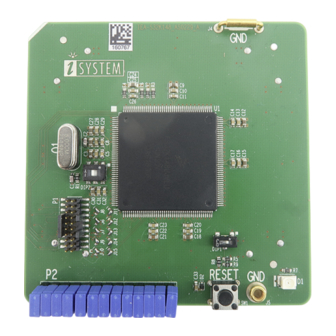
- Page 10 · TRACE CLOCK Port to PTC2 (alternative PTD16) · TRACE DATA0 Port to PTD7 (alternative PTD0) · TRACE DATA1 Port to PTD12 (alternative PTE4) · TRACE DATA2 Port to PTD11 (alternative PTD16) · TRACE DATA3 Port to PTD10 (alternative PTD15) P2: Power supply configuration Power supply of the Emulation Adapter is configured via the unshrouded 26-pin 2.54 mm header (P2).
- Page 11 If a different power source is used (e.g., a Standalone operation), remove all jumpers and apply 3V3 or 5V to: · VDD (pin 2), · VREFH (pin 4), Enclosed Power supply package (Power converter and Power adapter) simply plugs into the P2 header row, providing the necessary power supply for Emulation Adapter operation.
-
Page 12: Connectors
Connectors Be aware that debug and trace signals from the Emulation adapter superset device are not connected to the target board. They are exposed only to the connectors on the Emulation adapter. P1: CoreSight 20 connector CoreSight 20 connector P1 exposes debug and trace signals and has the following pinout on the Emulation Adapter side: Signal Dir- Signal Dir-... - Page 13 Power supply Use the enclosed IEA-PS Emulation Adapter Power converter and adapter. A Power supply package, which is delivered with the Emulation Adapter, is required when: · The Emulation Adapter is used as a standalone device . · The target board doesn’t provide an accurate supply voltage. ·...
- Page 14 source, insert the appropriate crystal into the Q1 socket, replace the default 22pF C1 and C2 ca- pacitors when necessary, and DIP switch DIP2 to position away from the white dot.
-
Page 15: Mechanical Information
Mechanical information Emulation Adapter Side view of the Emulation adapter complete setup - QFP Fixed Adaptation Top view of the Conversion board Top view of the Emulation Adapter Unit (mm) Ordering code IEA-S32K148 32.6 36.4 47.5 IEA-S32K148-xxxxx Solder parts QFP Top view of the Solder part Solder part Solder pad view In the case of soldering the Solder part manually, it’s highly recommended to prolong the solder... - Page 16 Recommended PCB footprint dimensions: Unit (mm) Ordering code IA48TQ-SOLDER 1.505 13.0 13.0 IA64ATQ-SOLDER 1.505 15.0 15.0 16.0 IA100TQ-SOLDER 16.5 1.125 17.0 17.0 2.15 19.55 19.55 IA144TQ-SOLDER 1.125 23.0 23.0 2.15 25.05 25.05 To view Emulation Adapter schematics, use the short link isystem.com/schematics.
-
Page 17: Assembly
Assembly Watch out that the pin 1 position and alignment of all pins. Avoid disassembling and reassembling the hardware setup too frequently. 1. Solder the Solder part [B] on the target PCB [A] to get a BA setup. Use the Surface Mount Technology (SMT) to solder the Solder parts to the target in- stead of the original microcontroller. - Page 18 Slot screw The Slot screw (30mm) is used to fix the Conversion board to the Solder part. The setup be- comes mechanically more robust.Screw the Conversion board to the Solder part first, before the Emulation Adapter is attached on top and watch out not to break out the Solder part, e.g., if you accidentally hit the Emulation Adapter from the side.
-
Page 19: Accessories
Accessories Ordering Code Description IC5700 iC5700 BlueBox IC5000 iC5000 BlueBox IC57031 IOM6 Hub (3 x FNet & FBridge) IC57040 IOM6 CAN/LIN IC57041 IOM6 ADIO Debug Adapters Listed Debug Adapters provide tracing functionality for the Emulation Adapter. Ordering Code Description IC50118-2 20-pin 1.27 mm CoreSight Debug Adapter IC50118-LV 20-pin 1.27 mm Low Voltage CoreSight Debug Adapter... - Page 20 Visit our website for: · Support - isystem.com/support · Tutorials - isystem.com/start · Knowledge Base - kb.isystem.com www.isystem.com...
Need help?
Do you have a question about the iSYSTEM NXP S32K148 and is the answer not in the manual?
Questions and answers