
Related Manuals for TASKING INFINEON TC265DE


Summary of Contents for TASKING INFINEON TC265DE
- Page 1 INFINEON TC265DE EMULATION ADAPTER HARDWARE USER MANUAL V2.1, May 2024 www.tasking.com...
- Page 2 Use included power cord and power supply The enclosed power supply has been approved for use by TASKING. Please contact TASKING if you need to consider an alternative power.
-
Page 3: Table Of Contents
Adaptation packages content ................. 6 Operation ......................7 Adaptation setup ....................8 Screw s ................................ 9 Configuration ....................... 10 Connectors ......................13 Power supply package ..................14 Standalone operation ................... 15 Measurement board ..................... 16 Mechanical information .................. 17 Schematics ..................... 19 www.tasking.com... -
Page 4: Introduction
Introduction Infineon TC265DE Emulation Adapter primary use case is providing AURORA GigaBit Trace (AGBT) functionality for the TC265 device in the QFP144 package featuring no trace functionality. The Emulation Adapter is based on the 216-pin emulation device. The Emulation Adapter might differ in some peripherals from the target device; therefore, the device datasheet should be checked. -
Page 5: Package Content
Power converter Power adapter Ordering code: Ordering code: Ordering code: IEA-TC265DE IEA-PS IT9V-PS GND Wire Measurement board (optional) Ordering code: Ordering code: BB-WIRE IAMTC265DE If you purchase the Power supply package individually, the Power adapter (IT9V-PS) must be ordered separately. www.tasking.com... -
Page 6: Adaptation Packages Content
Solder part IEA-TC265DE-TQ144 Fixed IA144TQ-SOLDER Fixed Adaptation The adaptation is elivered with a slot screw, which can be used to achieve a more solid and stable fixing of the Conversion board and the Solder part. Conversion board Solder part www.tasking.com... -
Page 7: Operation
Operation Emulation Adapter offers the following adaption setup: · Fixed Adaptation Top / Bottom side of the Emulation Adapter Introduction to Emulation Adapter (video) How to connect Hardware (video) isystem.com/ea-intro isystem.com/connect-hardware www.tasking.com... -
Page 8: Adaptation Setup
Adaptation setup Fixed Adaptation www.tasking.com... -
Page 9: Screws
Emulation Adapter is attached on top and watch out not to break out the Solder part, e.g., if you accidentally hit the Emulation Adapter from the side. Short Hexagon socket screw Short Hexagon socket screw, which comes with the Solder part, is not applicable with this Emulation Adapter setup. www.tasking.com... -
Page 10: Configuration
Q3 is not populated. Note that C1 and C2 values are valid for 20MHz crystal only. If different crystal is used, the default 10 pF capacitors must be replaced with proper value. J5 & J6: GND connecting points J5 and J6 provide grounding points on the Emulation Adapter. www.tasking.com... - Page 11 (floating) while the TC265DE PORST signal is low. This ensures embedded voltage regulators EVR33 and EVR13 are active by default. As soon as the PORST line is released from the low state, the HWCFG[0:2, 6] pins get connected to the target via the emulation adapter logic. www.tasking.com...
- Page 12 In principle, pins 3-4, 5-6, 7-8, must be bridged only but for the convenience and ease of use all jumpers are set, except for pins 25-26. Pin 26 is the polarizer key preventing incorrect connection of the IEA-PS power supply, when connected. www.tasking.com...
-
Page 13: Connectors
Signal Direction is described from the BlueBox perspective. Be aware that debug and trace signals from the Emulation adapter superset device are not connected to the target board. They are exposed only to the connectors on the Emulation adapter. www.tasking.com... -
Page 14: Power Supply Package
Be careful not to supply 5 V to the microcontroller power supply pin which has declared maximum voltage 3.3 V! Refer to microcontroller documentation for detailed information. External power supply requirements: Min Voltage Max Voltage Min Power 12 V www.tasking.com... -
Page 15: Standalone Operation
8) signals. The emulation adapter comes delivered together with the IEA-PS emulation adapter power supply, which simply plugs into the P2 header row, providing the necessary power supply for emulation adapter standalone operation. Double check that the IEA-PS emulation adapter power supply is configured properly for this particular emulation adapter. www.tasking.com... -
Page 16: Measurement Board
CPU signals are nicely marked) that matches your order. The black panel is placed over the Measurement board. Top view of the Measurement board Layout board example for the Measurement board Not available in every Emulation Adapter or every MCU pin count. www.tasking.com... -
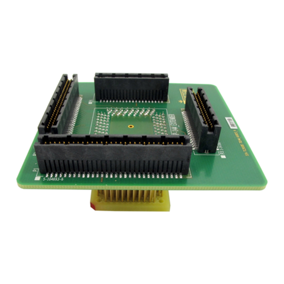
Page 17: Mechanical Information
Solder part solder pad view Top view of the Solder part Side view of the Solder part Side view of the Emulation adapter complete setup - QFP Fixed Adaptation Top view of the Emulation Adapter Top view of the Conversion board www.tasking.com... - Page 18 SOLDER Use the Surface Mount Technology (SMT) to solder the Solder parts to the user target board instead of the original microcontroller. iSYSTEM provides this soldering service on request too. Emulation Adapter Unit (mm) IEA-TC265DE 32.6 47.5 IEA-TC265DE- TQ144 www.tasking.com...
-
Page 19: Schematics
Optionally, the user could also design his target directly providing connection for the emulation adapter via the P3-P6 connectors. Connectors being used on the emulation adapter side are TE connectivity female connectors, part number: 0-0104652-4 (40-pin connector) and 0-0104652-6 (60-pin connector). The target must feature male matching connectors. www.tasking.com... - Page 20 Visit our website for: · Support - isystem.com/support · Tutorials - isystem.com/start · Knowledge Base - kb.isystem.com www.tasking.com www.tasking.com...
Need help?
Do you have a question about the INFINEON TC265DE and is the answer not in the manual?
Questions and answers