
Related Manuals for TASKING CYPRESS CYT2BL


Summary of Contents for TASKING CYPRESS CYT2BL
- Page 1 CYPRESS CYT2BL EMULATION ADAPTER HARDWARE USER MANUAL V1.6, September 2024 www.tasking.com...
- Page 2 Use included power cord and power supply The enclosed power supply has been approved for use by TASKING. Please contact TASKING if you need to consider an alternative power.
-
Page 3: Table Of Contents
Adaptation packages content ................. 6 Operation ......................8 Adaptation setups ....................9 Screw s ..............................11 Configuration ....................... 12 Connectors ......................17 Power supply package ..................18 Standalone operation ................... 19 Mechanical information .................. 20 Accessories ....................22 User Notes ...................... 23 www.tasking.com... -
Page 4: Introduction
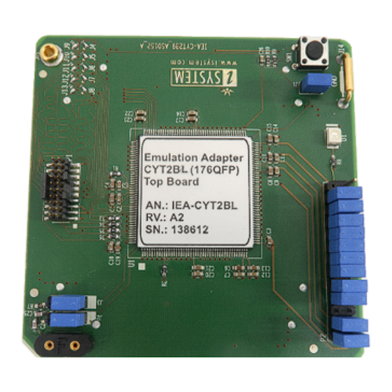
Introduction Cypress CYT2BL Emulation Adapter is based on the 176-pin CYT2BL superset device and provides full trace capabilities for the · 64-pin · 80-pin · 100-pin · 144-pin Traveo II CYT2BL Adaptation, where trace port is not available or lacks the full trace capability. -
Page 5: Package Content
Package content Cypress IEA-CYT2BL Emulation Adapter is delivered with all components required for Standalone operation. Adaptation package for the Target board must be ordered separately. Power supply package Cypress CYT2BL Emulation Adapter Power converter Power adapter Ordering code: Ordering code:... -
Page 6: Adaptation Packages Content
Conversion board and the Solder part. Conversion board Solder part Flex Adaptation with Wire adapter This part provides a flexible connection of the Emulation Adapter to the Solder part as an alternative to the fixed connection. Conversion board Solder part www.tasking.com... - Page 7 (oscilloscope, logic analyzer), its use provides easy access to all MCU pins. It is delivered together with an Layout board (chip signals are clearly marked), which is placed over the Measurement board. Measurement board (optional) Layout board example for the Measurement board Ordering code: IAMCYT2B www.tasking.com...
-
Page 8: Operation
Operation Emulation Adapter offers the following setups: · Fixed Adaptation · Flex Adaptation(with Wire adapter) Top/bottom side of the Emulation Adapter www.tasking.com... -
Page 9: Adaptation Setups
Adaptation setups Fixed Adaptation www.tasking.com... - Page 10 Flex Adaptation www.tasking.com...
-
Page 11: Screws
Emulation Adapter is attached on top and watch out not to break out the Solder part, e.g., if you accidentally hit the Emulation Adapter from the side. Short Hexagon socket screw Short Hexagon socket screw, which comes with the Solder part, is not applicable with this Emulation Adapter setup. www.tasking.com... -
Page 12: Configuration
16MHz external clock (XOSC) source to the emulation device. If a different clock frequency is required, insert appropriate crystal into the Q1 socket and replace C24 (default 10pF populated) and C25 (default 10pF populated) accordingly. Crystal socket Q1 is per default not populated (NP). Crystal socket Q1below: www.tasking.com... - Page 13 P18 (J9 – J13). If P18 on user target board is used for any other purpose than trace, Emulation Adapter allows changing the trace source to port P22 (J4 – J8) with relocation of the jumpers. Soldered jumpers J4-J13 on EA on the image below: www.tasking.com...
- Page 14 Default position on P18 Optional position on P22 www.tasking.com...
- Page 15 SoC Initialization section. Via the Parameters options CYT2Bx_TraceInit.cpp and depending on the user target board configuration allocate: · TRACE CLOCK Port to PORT 18 (or PORT 22) · TRACE DATAn PORT to PORT 18 (or PORT 22) www.tasking.com...
- Page 16 P3 – P6: Emulation device pinout P3, P4, P5, P6 pinouts match the pinout of the emulation device (176QFP). Refer to the microcontroller documentation for pin assignment. J14 and J15: GND connecting points J14 and J15 provide grounding points on the Emulation Adapter. www.tasking.com...
-
Page 17: Connectors
Signal Direction is described from the BlueBox perspective. Be aware that debug and trace signals from the Emulation Adapter superset device are not connected to the target board. They are exposed only to the connectors on the Emulation adapter. www.tasking.com... -
Page 18: Power Supply Package
Be careful not to supply 5 V to the microcontroller power supply pin, which has declared a maximum voltage 3.3 V! Refer to the microcontroller documentation for detailed information on power supply. P3 connector on the Power Supply board External power supply requirements: Min Voltage Max Voltage Min Power 12 V www.tasking.com... -
Page 19: Standalone Operation
If user target’s crystal circuit microcontroller oscillator (if available) is not an adequate clock source, insert appropriate crystal into the Q1 socket, replace the default 10pF C24 and C25 capacitors when necessary and place jumpers J2 and J3 in 2-3 position. www.tasking.com... -
Page 20: Mechanical Information
Solder part solder pad view Top view of the Solder part Side view of the Solder part Side view of the Emulation adapter complete setup - QFP Fixed Adaptation Top view of the Emulation Adapter Top view of the Conversion board www.tasking.com... - Page 21 Use the Surface Mount Technology (SMT) to solder the Solder parts to the user target board instead of the original microcontroller. iSYSTEM provides this soldering service on request too. Emulation Adapter Unit (mm) IEA-CYT2BL 32.6 47.5 IEA-CYT2BL-xxxx To view Emulation Adapter schematics, use the short link isystem.com/schematics. www.tasking.com...
-
Page 22: Accessories
Active Probe Parallel IC71801 / IC57801 Active Probe Debug IC70118 20-pin 1.27 mm Arm CoreSight Adapter IC50118-2 20-pin 1.27 mm CoreSight Debug Adapter IC50118-LV 20-pin 1.27 mm Low Voltage CoreSight Debug Adapter More information about our products via sales@tasking.com. www.tasking.com... -
Page 23: User Notes
User Notes This page is intentionally left blank. www.tasking.com... - Page 24 This page is intentionally left blank. www.tasking.com...
- Page 25 Visit our website for: · Support - support.tasking.com · Getting started - isystem.com/start · Knowledge Base - kb.tasking.com www.tasking.com www.tasking.com...
Need help?
Do you have a question about the CYPRESS CYT2BL and is the answer not in the manual?
Questions and answers